The Illustrated Network- P44 pptx
Bạn đang xem bản rút gọn của tài liệu. Xem và tải ngay bản đầy đủ của tài liệu tại đây (435.67 KB, 10 trang )
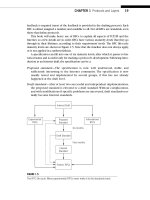
is the 2-byte Attribute Type. There is a structure to the Attribute Type fi eld, as shown
in Figure 15.7. There are four fl ag bits, four unused bits, and then an 8-bit Attribute
Type code.
There are other attribute codes in use with BGP, but these are not discussed in this
chapter. One of the most important of these other attributes is the Extended Commu-
nity attribute used in VPNs.
The Update message ends with a variable-length NLRI fi eld. Each NLRI (route)
is a Length/Prefi x pair. The length indicates the number of bits that is signifi cant
in the following prefi x. There is no length fi eld for this list that ends the Update
message. The number of NLRIs present is derived from the known length of all of the
other fi elds.
So, instead of saying “here’s a route and these are its attributes…” for every NLRI
advertised the Update message basically says “here’s a group of path attributes and here
are the routes that these apply to…” This cuts down on the number of messages that
needs to be sent across the network. In this way, each Update message forms a unit of
its own and has no further fragmentation concerns.
The Notifi cation Message
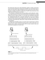
Error messages in BGP have an 8-bit Error Code, an 8-bit Subcode, and a variable-length
Data fi eld determined by the Error Code and Subcode. The format of the BGP Notifi ca-
tion message is shown in Figure 15.8.
8 bits 8 bits
OTPEUUUU Attribute Type Code
Flag bits:
O: Optional bit
0 5 Optional
1 5 Well known
T: Transitive bit
0 5 Transitive
1 5 Nontransitive
P: Partial bit
0 5 Optional transitive attribute is partial
1 5 Optional transitive attribute is complete
E: Extended length bit
0 5 Attribute length is 1 byte
1 5 Attribute length is 2 bytes
U: Unused
FIGURE 15.7
The BGP Attribute Type format. This is how NRLIs are grouped.
CHAPTER 15 Border Gateway Protocol 399
A full discussion of BGP Notifi cation codes and subcodes is beyond the scope of
this chapter. The major Error Codes are Message Header Error (1), Open Message Error
(2), Update Message Error (3), Hold Timer Expired (4), Finite State Machine Error (5),
used when the BGP implementation gets hopelessly confused about what it should be
doing next, and Cease (6), used to end the session.
32 bits
Data
Error SubcodeError Code
1 byte 1 byte 1 byte 1 byte
Error codes:
1: Message header error
2: Open message error
3: Update message error
4: Hold timer expired
5: Finite State Machine error
6: Cease
FIGURE 15.8
The BGP Notifi cation message format. BGP benefi ts from using TCP as a transport protocol.
400 PART III Routing and Routing Protocols
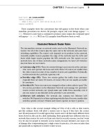
QUESTIONS FOR READERS
Figure 15.9 shows some of the concepts discussed in this chapter and can be used to
help you answer the following questions.
“I don’t know
10.0.75.1!
It’s not in this AS!”
Router
192.168.14.1
“Oh! I know how to reach
192.168.14.1”
IBGP
without
NHS
IBGP with
NHS
EBGP
(No IGP)
Router in
AS 65127
“I can reach
10.10.12/24.
Use 10.0.75.1
as a next hop.”
10.0.75.2 10.0.75.1
FIGURE 15.9
How Next Hop Self allows internal routers to forward packets for BGP routes. Border router
192.168.14.1 substitutes its own address for the “real” next hop.
1. BGP distributes “reachability” information and not routes. Why doesn’t BGP
distribute route information?
2. What does it mean to say that the BGP is a “path-vector” protocol?
3. What is “next hop self” and why is it important in BGP?
4. Which two major BGP router confi gurations are employed to deal with BGP
scaling?
5. What are the ten major BGP attributes?
401
What You Will Learn
In this chapter, you will learn how multicast routing protocols allow multicast
traffi c to make its way from a source to interested receivers through a router-based
network. We’ll look at both dense and parse multicast routing protocols, as well as
some of the other protocols used with them (such as IGMP).
You will learn how the PIM rendezvous point (RP) has become the key
component in a multicast network. We’ll see how to confi gure an RP on the
network and use it to deliver a simple multicast traffi c stream to hosts.
Multicast
16
If the Internet and TCP/IP are going to be used for everything from the usual data
activities to voice and video, something must be done about the normal unicast packet
addressing refl ecting one specifi c source and one specifi c destination. Almost every-
thing described in this book so far has featured unicast, although multicast addresses
have been mentioned from time to time—especially when used by routing protocols.
The one-to-many operation of multicast is a technique between the one-to-one
packet delivery operation of unicast and the one-to-all operation of broadcast. Broad-
casts tend to disrupt hosts’ normal processing because most broadcasts are not really
intended for every host yet each receiving host must pay attention to the broadcast
packet’s content. Many protocols that routinely used broadcasts, such as RIPv1, were
replaced by versions that used multicast groups instead (RIPv2, OSPF). Even the proto-
cols in IPv4 that still routinely use broadcast, such as ARPing to fi nd the MAC address
that goes with an IP address, have been replaced in IPv6 with multicast-friendly versions
of the same procedure.
Multicast protocols are still not universally supported on much of the Internet. Then
how do large numbers of people all watch the same video feed from a Web server
(for example) at the same time? Today, this is normally accomplished with numerous
unicast links, each running from the server to every individual host. This works, but
it does not scale. Can a server handle 100, 1000, or 1,000,000 simultaneous users?
Many-to-many multicast applications, such as on-line gaming and gambling sites, use
CE0
lo0: 192.168.0.1
fe-1/3/0: 10.10.11.1
MAC: 00:05:85:88:cc:db
(Juniper_88:cc:db)
IPv6: fe80:205:85ff:fe88:ccdb
P9
lo0: 192.168.9.1
PE5
lo0: 192.168.5.1
P4
lo0: 192.168.4.1
so-0/0/1
79.2
so-0/0/1
24.2
so-0/0/0
47.1
so-0/0/2
29.2
so-0/0/3
49.2
so-0/0/3
49.1
so-0/0/0
59.2
so-0/0/2
45.1
so-0/0/2
45.2
so-0/0/0
59.1
ge-0/0/3
50.2
ge-0/0/3
50.1
DSL Link
Ethernet LAN Switch with Twisted-Pair Wiring
bsdclient lnxserver wincli1
em0: 10.10.11.177
MAC: 00:0e:0c:3b:8f:94
(Intel_3b:8f:94)
IPv6: fe80::20e:
cff:fe3b:8f94
eth0: 10.10.11.66
MAC: 00:d0:b7:1f:fe:e6
(Intel_1f:fe:e6)
IPv6: fe80::2d0:
b7ff:fe1f:fee6
LAN2: 10.10.11.51
MAC: 00:0e:0c:3b:88:3c
(Intel_3b:88:3c)
IPv6: fe80::20e:
cff:fe3b:883c
LAN2: 10.10.11.111
MAC: 00:0e:0c:3b:87:36
(Intel_3b:87:36)
IPv6: fe80::20e:
cff:fe3b:8736
winsvr1
LAN1
Los Angeles
Office
Rendezvous
Point (RP)
Wireless
in Home
Best-
AS 65459
Solid rules
ϭ
SONET/SDH
Dashed rules
ϭ
Gig Ethernet
Note: All links use 10.0.x.y
addressing only the last
two octets are shown.
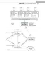
FIGURE 16.1
Portion of the Illustrated Network used for the multicast examples. The RP will be router PE5, and
the ISPs have merged into a single AS for this chapter.
404 PART III Routing and Routing Protocols
CE6
lo0: 192.168.6.1
fe-1/3/0: 10.10.12.1
MAC: 0:05:85:8b:bc:db
(Juniper_8b:bc:db)
IPv6: fe80:205:85ff:fe8b:bcdb
Ethernet LAN Switch with Twisted-Pair Wiring
bsdserver lnxclient winsvr2 wincli2
eth0: 10.10.12.77
MAC: 00:0e:0c:3b:87:32
(Intel_3b:87:32)
IPv6: fe80::20e:
cff:fe3b:8732
eth0: 10.10.12.166
MAC: 00:b0:d0:45:34:64
(Dell_45:34:64)
IPv6: fe80::2b0:
d0ff:fe45:3464
LAN2: 10.10.12.52
MAC: 00:0e:0c:3b:88:56
(Intel_3b:88:56)
IPv6: fe80::20e:
cff:fe3b:8856
LAN2: 10.10.12.222
MAC: 00:02:b3:27:fa:8c
IPv6: fe80::202:
b3ff:fe27:fa8c
LAN2
New York
Office
P7
lo0: 192.168.7.1
PE1
lo0: 192.168.1.1
P2
lo0: 192.168.2.1
so-0/0/1
79.1
so-0/0/1
24.1
so-0/0/0
47.2
so-0/0/2
29.1
so-0/0/3
27.2
so-0/0/3
27.1
so-0/0/2
17.2
so-0/0/2
17.1
so-0/0/0
12.2
so-0/0/0
12.1
ge-0/0/3
16.2
ge-0/0/3
16.1
Ace ISP
Global Public
Internet
CHAPTER 16 Multicast 405
multiple point-to-point meshes of links in most cases. Even if modern server clusters
could do this, could all the routers and links handle this traffi c? Multicast uses the rout-
ers to replicate packets, not the servers.
However, interdomain (or even intersubnet) multicasting is a problem. IP multicast
is widely leveraged on localized subnets where it’s solely a question of host support.
Many-to-many applications have some fundamental scaling challenges and multicast
does not address these very well. For example, how does each host in a shared tree of
multicast traffi c manage the receipt of perhaps 50 video streams from participants?
Today, multicast is a key component of local IPv6 and IPv4 resource discovery
mechanisms and is not confi ned to enterprise applications. However, multicast appli-
cations are used mainly on enterprise networks not intended for the general public.
In the future, multicast must move beyond a world where special routers (not all rout-
ers can handle multicast packets) use special parts of the Internet (most famously, the
MBONE, or multicast backbone) to link interested hosts to their sources. Multicast must
become an integral part of every piece of hardware and software on the Internet.
Let’s look at a few simple multicast packets and frames on the Illustrated Network.
We don’t have any video cameras or music servers on the network to pump out con-
tent, but we do have the ability to use simple socket programs to generate a stream of
packets to multicast group addresses as easily as to unicast destinations. We could look
at multicast as used by OSPF or IPv6 router announcements, but we’ll look at simple
applications instead.
We’ll look at IPv4 fi rst, and then take a quick look at IPv6 multicasting. We’ll use the
devices shown in Figure 16.1 to illustrate multicast protocols, introducing the terms
used in multicast protocols as we go. We’ll explore all of the terms in detail later in the
chapter.
This chapter uses
wincli2 and lxnclient on LAN2 and wincli1 on LAN1. The router
PE5 will serve as our PIM sparse-mode RP. To simplify the number of multicast protocols
used, we’ve merged the two ISPs into Best-Ace ISP for this chapter. This means we will
not need to confi gure the Multicast Source Discovery Protocol (MSDP), which allows
receivers in an AS to fi nd RPs in another AS. A full investigation of MSDP is beyond the
scope of this chapter, but we will go over the basics.
A FIRST LOOK AT IPV4 MULTICAST
This section uses two small socket programs from the source cited in Chapter 12: the
excellent TCP/IP Sockets in C by Michael J. Donahoo and Kenneth L. Calvert. We’ll use
two programs run as MulticastReceiver and MulticastSender, and two free Windows
multicast utilities, wsend and wlisten.
Let’s start with two hosts on the same LAN. We’ll use lnxclient (10.10.12.166)
and wincli2 (10.10.12.222) for this exercise (both clients, but there’s no heavy mul-
ticasting going on). We’ll set the Linux client to multicast the text string HEY once
every 3 seconds onto the LAN using multicast group address 239.2.2.2 (multicasts
use special IP addresses for destinations) and UDP port 22222 (multicast applications
406 PART III Routing and Routing Protocols
often use UDP, and cannot use TCP). Naturally, we’ll set the multicast receiver socket
program on the Windows XP client to receive traffi c sent to that group.
It should be noted that the multicast group addresses used here are administra-
tively scoped addresses that should only reach a limited number of hosts and not be
used on the global public Internet, much like private IP addresses. However, we won’t
discuss how the traffi c to these groups is limited. This is mainly because there are some
operational disagreements about how to apply administratively scoped boundaries. We
are using scoped addresses primarily as an analogy for private IP addresses. We could
also have used GLOP addresses (discussed in this chapter) or addresses from the
dynamic multicast address block.
The receiver socket program does not generate any special messages to say, “Send
me content addressed to group
239.2.2.2.” We know it’s going to be there. Later,
we’ll see that a protocol called Internet Group Management Protocol (IGMP) sends
join or leave messages and knows what content is carried at this time by group
239.2.2.2 because of the Session Announcement Protocol and Source Description
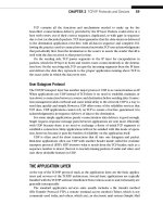
Protocol (SAP/SDP) messages it receives. In reality, multicast is a suite of protocols—
and much more is required to create a complete multicast application. However,
this little send-and-receive exercise will still reveal a lot about multicast. Figure 16.2
shows a portion of the Ethereal capture of the packet stream, detailing the UDP con-
tent inside the IP packet.
FIGURE 16.2
Multicast packet capture, showing the MAC address format used and the port in the UDP
datagram. Some IGMPv3 messages appear also.
CHAPTER 16 Multicast 407
The Ethernet frame destination address is in a special form, starting with 01 and
ending in 02:02:02—which corresponds to the 239.2.2.2 multicast group address.
We’ll explore the rules for determining this frame address in material following. Note
that the packet is addressed to the entire group, not an individual host (as in unicast).
How does the network know where to send replicated packets? Two strategies (dis-
cussed later in the chapter) are to send content everywhere and then stop if no one
says they are listening (fl ood-and-prune, or dense mode), or to send content only to
hosts that have indicated a desire to receive the content (sparse mode).
The fi gure also shows that the Windows XP receiver (
10.10.12.222) is generating
IGMPv3 membership reports sent to multicast group address 224.0.0.22 (the IGMP
multicast group). XP does this to keep the multicast content coming, even though
the socket sender program has no idea what it means. These messages from XP to the
IGMP group sometimes cause consternation with Windows network administrators,
who are not always familiar with multicast and wonder where the 224.0.0.22 “server”
could be.
Now let’s set our multicast group send program to span the router network from
LAN1 to LAN2. We’ll start the socket utility sending on wincli1 (10.10.11.51), using
multicast group 239.1.1.1 and UDP port 11111. The listener will still be wincli2
(10.10.12.222).
This is easy enough, and Ethereal on wincli1 shows a steady stream of multicast
traffi c being dumped onto LAN1. However, the Ethereal capture on wincli2 (which had
no problem receiving a multicast stream only moments ago) now receives absolutely
nothing. What’s wrong?
The problem is that the routers between LAN1 and LAN2 are not running a multicast
routing protocol. The router on LAN1 at 10.10.11.1 adjacent to the source receives
every multicast packet sent by wincli1. But the destination address of 239.1.1.1 is
meaningless when considered as a unicast address. No entry exists in the unicast rout-
ing table, and there is yet no multicast “routing table” (more properly, table for multicast
interface state) on the router network.
Before we confi gure multicast for use on our router network and allow multicast traf-
fi c to travel from LAN1 to LAN2, there are many new terms and protocols to explain—a
few of which we’ve already mentioned (IGMP, SAP/SDP, how a multicast group maps to
a frame destination address, and so on.) Let’s start with the basics.
MULTICAST TERMINOLOGY
Multicast in TCP/IP has developed a reputation of being more diffi cult to understand
than unicast. Part of the problem is the special terminology used with multicast, and
the implication that if something is not universally supported, it must be complicated
and diffi cult to understand. But there is nothing in multicast that is more complex than
subnet masking, multicast sockets are nearly the same as unicast sockets (except that
they don’t use TCP sockets), and many things that routing protocols do with multicast
packets are now employed in unicast as well (the reverse-path forwarding, or RFP
408 PART III Routing and Routing Protocols