The Illustrated Network- P65 pptx
Bạn đang xem bản rút gọn của tài liệu. Xem và tải ngay bản đầy đủ của tài liệu tại đây (293.01 KB, 10 trang )
CHAPTER
What You Will Learn
In this chapter, you will learn how SNMP is used to manage devices on a TCP/
IP network. We’ll explore the SNMP model with many servers (agents) and few
clients (managers).
You will learn about MIBs and the SMI tree for designating management
information. We also briefl y discuss RMON (remote monitor) and private manage-
ment information bases (MIBs).
Simple Network
Management Protocol
24
Network management, like network security, is often treated like an adjunct to the true
task of networking, which is to relentlessly shuttle bits about (i.e., until something goes
wrong). Then everyone wonders why it couldn’t be easier to fi gure out what went hay-
wire. Without network management facilities, the network is like driving a car without
fuel-level, water-temperature, or oil-pressure gauges. When the car slowly glides to a
halt, there are few clues of even where to start looking.
The Internet outgrew the humble go-have-a-look-at-it school of network manage-
ment by the late 1980s, when it seemed like colleges and universities were sticking
routers in every other building around the campus and then fi nding someone who
would not object to being placed in charge of the devices. Little did they realize that
they would be expected to ensure that the out-of-the-way device was functional day
and night, 365 days a year. They ran their portion of the Internet on a PING and a
prayer.
It’s not that management of network devices was unknown at the time, or deemed
unnecessary. Vendors always had some sort of management functions tucked away in
their software. The problem was that each vendor’s interface was different (sometimes
in the same product line), the client software expensive and proprietary, and the net-
work operations centers (NOCs) that existed tended to consist of rooms full of equip-
ment that no one knew how to operate equally well.
But knowing that network management was essential and creating a standard for
network management on the Internet were two different things. The international
CE0
lo0: 192.168.0.1
fe-1/3/0: 10.10.11.1
MAC: 00:05:85:88:cc:db
(Juniper_88:cc:db)
IPv6: fe80:205:85ff:fe88:ccdb
P9
lo0: 192.168.9.1
PE5
lo0: 192.168.5.1
P4
lo0: 192.168.4.1
so-0/0/1
79.2
so-0/0/1
24.2
so-0/0/0
47.1
so-0/0/2
29.2
so-0/0/3
49.2
so-0/0/3
49.1
so-0/0/0
59.2
so-0/0/2
45.1
so-0/0/2
45.2
so-0/0/0
59.1
ge-0/0/3
50.2
ge-0/0/3
50.1
DSL Link
Ethernet LAN Switch with Twisted-Pair Wiring
bsdclient lnxserver wincli1
eth0: 10.10.11.66
MAC: 00:d0:b7:1f:fe:e6
(Intel_1f:fe:e6)
IPv6: fe80::2d0:
b7ff:fe1f:fee6
LAN2: 10.10.11.51
MAC: 00:0e:0c:3b:88:3c
(Intel_3b:88:3c)
IPv6: fe80::20e:
cff:fe3b:883c
winsvr1
LAN1
Los Angeles
Office
Ace ISP
AS 65459
Wireless
in Home
SNMP
Client
(scli)
LAN2: 10.10.11.111
MAC: 00:0e:0c:3b:87:36
(Intel_3b:87:36)
IPv6: fe80::20e:
cff:fe3b:8736
Solid rules
ϭ
SONET/SDH
Dashed rules
ϭ
Gig Ethernet
Note: All links use 10.0.x.y
addressing only the last
two octets are shown.
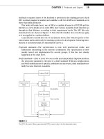
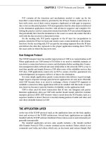
FIGURE 24.1
SNMP on the Illustrated Network, showing the hosts used as SNMP clients and the router with SNMP
enabled.
610 PART V Network Management
CE6
lo0: 192.168.6.1
fe-1/3/0: 10.10.12.1
MAC: 0:05:85:8b:bc:db
(Juniper_8b:bc:db)
IPv6: fe80:205:85ff:fe8b:bcdb
Ethernet LAN Switch with Twisted-Pair Wiring
bsdserver lnxclient winsvr2 wincli2
eth0: 10.10.12.166
MAC: 00:b0:d0:45:34:64
(Dell_45:34:64)
IPv6: fe80::2b0:
d0ff:fe45:3464
LAN2: 10.10.12.52
MAC: 00:0e:0c:3b:88:56
(Intel_3b:88:56)
IPv6: fe80::20e:
cff:fe3b:8856
LAN2: 10.10.12.222
MAC: 00:02:b3:27:fa:8c
IPv6: fe80::202:
b3ff:fe27:fa8c
LAN2
New York
Office
P7
lo0: 192.168.7.1
PE1
lo0: 192.168.1.1
P2
lo0: 192.168.2.1
so-0/0/1
79.1
so-0/0/1
24.1
so-0/0/0
47.2
so-0/0/2
29.1
so-0/0/3
27.2
so-0/0/3
27.1
so-0/0/2
17.2
so-0/0/2
17.1
so-0/0/0
12.2
so-0/0/0
12.1
ge-0/0/3
16.2
ge-0/0/3
16.1
Best ISP
AS 65127
Global Public
Internet
SNMP
Client
(scli)
SNMP-Enabled Router
CHAPTER 24 Simple Network Management Protocol 611
standard for network management, itself a new creation at the time, was the Com-
mon Management Information Services/Common Management Information Protocol
(CMIS/CMIP). However, this standard (geared to the needs of public telephony car-
riers) was loaded with features unnecessary to the Internet at the time. So, Internet
administrators took what they could from the ISO specifi cations and created SNMP
fairly independently.
SNMP CAPABILITIES
The need for network management information has to be weighed against the need for
security. Yet many organizations routinely run SNMPv1 on their network nodes, hubs,
or routers, and seldom take advantage of the heightened security available in many
SNMPv1 implementations or consider SNMPv2. Organizations routinely block Telnet
access to their routers, yet allow SNMP access without too much worry.
Just how much information can be gathered from a router running SNMPv1when
no steps have been taken to protect information? Quite a bit, actually.
Let’s enable SNMP on one of our routers, CE6, attached to LAN2, and use bsdclient
on LAN1 and bsdserver on LAN2 to see what we can do with SNMP. There are many
nifty GUIs available for SNMP, but we’ll use FreeBSD’s scli application to maximize
information and minimize clutter on the screen. We won’t be interested in traffi c
histograms or historical data anyway. The equipment used in this chapter is shown in
Figure 24.1.
Enabling SNMP on a Juniper router is very straightforward (just setting values to
the proper variables) and need not be shown. The following is the result of our initial
confi guration.
admin@CE6# show snmp
name Router_CE6;
description M71-Router;
contact WalterG;
There is much more we could have confi gured, and in fact this is really more than
we need. But it will allow us to ensure that it’s the right router. Now we can run a Unix
command-line management application on bsdclient called scli to router CE6. (We
haven’t put the routers in DNS, and many organizations don’t for security purposes, so
we’ll access the router by an interface IP address instead of by name.)
bsdclient# scli 10.10.12.1
100-scli version 0.2.12 (c) 2001-2002 Juergen Schoenwaelder
100-scli trying SNMPv2c good
(10.10.12.1) scli >
We are now running SNMPv2 to the router. Note that scli is an interactive applica-
tion with its own > prompt, like nslookup, so we can execute all types of commands
612 PART V Network Management
(known through help) at this point until an exit takes us out to the shell again. Let’s
ensure that we have the right router and examine the system information.
(10.10.12.1) scli > show system info
Name: Router_CE6
Address: 10.10.12.1:161
Description: M7i-router
Contact: WalterG
Location:
Vendor: unknown (enterprises.2636)
Services: network
Current Time: 2008-02-28 20:11:36 -07:00
Agent Boot Time: 2008-02-21 20:44:12 -08:00
System Boot Time: 2008-02-21 20:43:27 -08:00
System Boot Args: /kernel
Users: 3
Processes: 61 (532 maximum)
Memory: 256M
Interfaces: 50
Interface Swap: 2008-02-21 20:45:31 -08:00
(10.10.12.1) scli >
That’s the router all right. Note that we get a lot more information than we entered.
And some people would be very nervous about the system details that SNMP has gath-
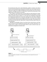
ered from this router. But let’s look at SNMP in action fi rst. Figure 24.2 shows the SNMP
messages and details. One response is of particular interest—the one that has the infor-
mation we entered on the router. Most of the information displayed at the start of the
show command can be picked out of the lower pane in the figure.
FIGURE 24.2
SNMP session to router CE6.
CHAPTER 24 Simple Network Management Protocol 613
Let’s see what harm we can cause with SNMP by changing something.
(10.10.12.1) scli > set system contact NotMe
500 noResponse 1.00 vpm
(10.10.12.1) scli >
The noResponse tells us that our request was ignored by CE6. Most devices will enable
SNMP with read-only access unless told otherwise. Still, there’s a lot of information
available about good old router CE6, such as the following:
(10.10.12.1) scli > show interface
# show interface info [10.10.12.1] [2008-02-28 20:43:38 -07:00]
INTERFACE STATUS MTU TYPE SPEED NAME DESCRIPTION
1 UUCN 1514 ethernetCsmacd 100m fxp0 fxp0
2 UUCN 1514 ethernetCsmacd 100m fxp1 fxp1
4 UUNN 1496 mplsTunnel 0 lsi lsi
5 UUNN 2147483647 other 0 dsc dsc
6 UUNN 2147483647 softwareLoopback 0 lo0 lo0
7 UUNN 2147483647 other 0 tap tap
8 UUNN 2147483647 tunnel 0 gre gre
9 UUNN 2147483647 tunnel 0 ipip ipip
10 UUNN 2147483647 tunnel 0 pime pime
11 UUNN 2147483647 tunnel 0 pimd pimd
12 UUNN 2147483647 tunnel 0 mtun mtun
13 UUNN 1500 propVirtual 100m fxp0.0 fxp0.0
14 UUNN 1514 propVirtual 100m fxp1.0 fxp1.0
16 UUNN 2147483647 softwareLoopback 0 lo0.0 lo0.0
21 UUCN 4474 sonet 155m so-0/0/0 so-0/0/0
22 UUNN 4470 ppp 155m so-0/0/0.0 so-0/0/0.0
23 UUCN 4474 sonet 155m so-0/0/1 so-0/0/1
24 UUNN 4470 ppp 155m so-0/0/1.0 so-0/0/1.0
25 UUCN 4474 sonet 155m so-0/0/2 so-0/0/2
26 UUNN 4470 ppp 155m so-0/0/2.0 so-0/0/2.0
27 UUCN 4474 sonet 155m so-0/0/3 so-0/0/3
28 UUNN 4470 ppp 155m so-0/0/3.0 so-0/0/3.0
29 UUNN 2147483647 softwareLoopback 0 lo0.16385 lo0.16385
30 UUNN 2147483647 tunnel 800m pd-1/2/0 pd-1/2/0
31 UUNN 2147483647 tunnel 800m pe-1/2/0 pe-1/2/0
32 UUNN 2147483647 tunnel 800m gr-1/2/0 gr-1/2/0
33 UUNN 2147483647 tunnel 800m ip-1/2/0 ip-1/2/0
34 UUNN 2147483647 tunnel 800m vt-1/2/0 vt-1/2/0
35 UUNN 2147483647 tunnel 800m mt-1/2/0 mt-1/2/0
36 UUNN 0 tunnel 800m lt-1/2/0 lt-1/2/0
37 UUCN 1514 ethernetCsmacd 100m fe-1/3/0 fe-1/3/0
38 UDCN 1514 ethernetCsmacd 100m fe-1/3/1 fe-1/3/1
39 UUNN 2147483647 tunnel 800m pd-0/3/0 pd-0/3/0
40 UUNN 2147483647 tunnel 800m pe-0/3/0 pe-0/3/0
41 UUNN 2147483647 tunnel 800m gr-0/3/0 gr-0/3/0
614 PART V Network Management
42 UUNN 2147483647 tunnel 800m ip-0/3/0 ip-0/3/0
43 UUNN 2147483647 tunnel 800m vt-0/3/0 vt-0/3/0
44 UUNN 2147483647 tunnel 800m mt-0/3/0 mt-0/3/0
45 UUNN 0 tunnel 800m lt-0/3/0 lt-0/3/0
46 UDCN 1504 e1 2m e1-0/2/0 e1-0/2/0
47 UDCN 1504 e1 2m e1-0/2/1 e1-0/2/1
48 UDCN 1504 e1 2m e1-0/2/2 e1-0/2/2
Byte 2969
And this is only part of it. Just imagine if someone managed to break in and . . . but
wait: All we did is use a router interface’s IP address. No breaking in was needed.
What can we do to tighten things up? Let’s limit SNMP access to a single interface
on the router, and a single host reachable through the interface. The interface will be
LAN2, on fe-1/3/0, not surprisingly. We’ll use the LAN2 host bsdserver so that we can
still use scli. We’ll also let an administrator with root privileges on bsdserver make
changes with the set request in the SNMP community (a sort of SNMP “password,” but
it’s really not) called locallan. Almost all of this is confi gured on the router, not the
host. The scli limitation to execute a remote set command is a function of the applica-
tion. The following presents the new router confi guration.
set snmp name Router_CE6;
set snmp description M7i-router;
set snmp contact WalterG;
set snmp interface fe-1/3/0.0; # restrict SNMP to the LAN2 interface
set snmp view syscontact oid sysContact include; # let the manager change
the sysContact
set snmp community locallan view sysContact; # establish new community
string and add sysContact to view. . .
set snmp community locallan authorization read-write; # . . .and let it be
read and write access. . .
set snmp community locallan clients 10.10.12.77/32; # . . .but only from
bsdserver for the locallan community string
We have to explicitly add the sysContact object ID to a “view” for the community
string locallan if we are going to allow the network manager on bsdserver to change
the value of that object. Back on bsdclient, the effects of these changes are immediate.
(10.10.12.1) scli > show ip
500 noResponse
500 noResponse
500 noResponse
500 noResponse
500 noResponse
(10.10.12.1) scli >
But things are different once we switch to bsdclient (and remember to use the com-
munity string locallan).
CHAPTER 24 Simple Network Management Protocol 615
> bsdserver# scli
100-scli version 0.2.12 (c) 2001-2002 Juergen Schoenwaelder
scli > open 10.10.12.1 locallan
100-scli trying SNMPv2c good
(10.10.12.1) scli > set system contact NotMe
(10.10.12.1) scli > show system
# show system info [10.10.12.1] [2008-02-28 21:02:07 -07:00]
Address: 10.10.12.1:161
Contact: NotMe
(10.10.12.1) scli >
If we forget to add the object explicitly to the community on the router, bsdserver
still has access but will not be able to write to the object.
(10.10.12.1) scli > set system contact NotMe
500 noAccess @ varbind 1
(10.10.12.1) scli >
By now it should be obvious that SNMP can be a powerful network management
tool, independent of remote-access or vendor-specifi c management techniques. How-
ever, all of this talk about objects, community strings, SNMPv1, and v2 can be confusing.
SNMP introduces a lot of terms and concepts. Let’s start at the beginning and see just
what SNMP can do and how it does it.
THE SNMP MODEL
This section takes a more detailed look at how SNMP, versions 1 and 2, works. This
chapter identifi es the shortcomings of SNMPv1 that led to the creation of SNMPv2, and
then shows what SNMPv3 will add to SNMP. SNMP remains the most popular and most
viable method of managing networks today, let alone the Internet.
All network management standards, not just SNMP, work by means of what is known
as the agent/manager model. This is not really a new term or concept. The term “agent/
manager model” is essentially the client/server model idea extended to network man-
agement. A manager is just a management console in the NOC running the network
management software, not an actual human being. An agent is software that runs on all
manageable devices on the network. As in the client/server model, managers “talk” and the
agents “listen.” So, managers are clients for network management purposes and agents are
servers for network management purposes. Obviously, a major difference in the agent/
manager model from traditional client/server is that in a network management situation,
there are many servers (agents) and generally only a few clients (management consoles).
The manager running in the network management station (or any host setup to run
it) sends commands to the agent software on the managed device using a network man-
agement protocol that both the manager and agent understand. The agent responds and
then waits (or “listens”) for a further command, and so on. The command may be gener-
ated by the manager software periodically, without human intervention, and the results
616 PART V Network Management
Network Management Station
Network
Management
Application
Network
Management
Application
Network
Management
Application
SNMP Manager
SNMP Agent
Read/write configuration
Read/write status
Read statistics
Read errors
Respond to requests
Report errors
“Trap” certain events
MIB
Managed Device
Logical Database
Configuration Data
Status Parameters
Statistics
stored in a manager console database for future reports or reference. Alternatively, the
commands may be generated by NOC personnel using the manager console to solve
outstanding network problems, perform routine testing, and so forth. In the case of a
serious event, such as major link failure, an alarm (called a trap in SNMP) is generated
without anyone asking. Most servers, hubs, routers, and even end-user devices sold
today have built-in SNMP agent software that does not usually have to be purchased
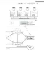
separately. The SNMP model of network management is shown in Figure 24.3.
Note that network managers can both monitor the status of the device and actu-
ally change the confi guration (a dangerous capability that requires careful consider-
ations if it is to be allowed at all). The network management station typically keeps
the historical information about the network device (devices have better things to
do), and has a number of applications whose main goal is to provide detailed reports
about the network’s performance, often in a graphical format designed for visual
impact.
In addition, all network management standards provide for a special type of agent
(known as the proxy agent) to provide the manager console with management informa-
tion about network devices that do not understand the network management protocol.
Of course, the network devices must understand some type of network management
protocol or they would not be manageable at all. But the proxy agent performs a type
of gateway function to translate back and forth between the network manager console
protocol and the different network management protocol, often proprietary, under-
stood by the network devices accessed by the proxy agent.
FIGURE 24.3
SNMP model, showing that an agent has access to a MIB in the managed devices.
CHAPTER 24 Simple Network Management Protocol 617
The MIB and SMI
The agent software has access to the current value of various objects in the managed
device. The exact function and meaning of an object, and the relationship of one object
to another, is described in the MIB for the managed device. The MIB is a crucial con-
cept in all network management standards, not only in SNMP, although there are many
MIBs for devices used on the Internet.
The MIB is a database description of all fi elds (objects) that make up the totality
of information an agent can furnish to a manager console when requested. So, a MIB is
most often just a piece of paper (RFC) that says things such as “the fi rst fi eld is alphanu-
meric, 20 characters long, and contains the name of the vendor” and “the fi fth fi eld is an
integer and contains the number of bad packets received.” Not that this is rendered in
plain English. A special ISO “language” called ASN.1 (Abstract Syntax Notation version
1) is used to represent all fi elds of the MIB database in very terse and cryptic language
that all MIB implementers understand.
The SMI
The problem with trying to manage all possible network device agents with a single
management protocol is that there are so many different types of network devices.
Some deal with packets (routers), and some with frames (bridges). Some are quite
simple (hubs), and some are very complex (switches). The challenge is to fi nd a way to
sort out all of the possible MIB variables in a standard fashion so that any implementa-
tion of the network manager console protocol will be able to request the value of any
particular object accessible by any agent. Fortunately, standards organizations have all
agreed on and defi ned a standard structure for network management information.
The SNMP developers defi ned a Structure of Management Information (SMI) tree
in RFC 1155. The same SMI is defi ned in ISO 10165, where it is called the Management
Information Model (MIM), and in ITU-T X.720, X.721, and X.722.
MIB information is structured through the use of a naming tree known as the SMI
conceptual tree. Figure 24.4 shows the SMI conceptual tree with the emphasis on
SNMP MIB defi nitions.
The root of the tree is unlabeled. All branches of the tree from the root have both
labels and numbers associated with them. All SNMP MIB objects are under the branch
that leads from ISO (1) to Identifi ed Organizations (3) to the Department of Defense
(DoD) (6) to the Internet (1). At the lowest branches of the tree are the MIB objects
themselves. These are organized into MIB-I (the original SNMP defi nitions) and MIB-II
(extended SNMP defi nitions).
The system group of MIB-II is probably the most commonly used and easily under-
stood of all MIB objects in SNMP. The System(1) group contains seven objects that
provide a general description of the network device. The seven objects are:
■ sysDescr(1)—A description of the network device (“router,” “hub,” etc.)
■ sysObjectID(2)—The identifi er of the device’s private MIB location, if any
(discussed more fully in material following)
618 PART V Network Management