The Illustrated Network- P71 pptx
Bạn đang xem bản rút gọn của tài liệu. Xem và tải ngay bản đầy đủ của tài liệu tại đây (173.68 KB, 10 trang )
is wildly erratic and thus wasted much of the time. Private networks are designed for
peak loads, such as end-of-month or end-of-quarter frenzies, and sit idle most of the
time. The PSTN is no exception, by the way, and is designed (in the United States)
for the 5 days of maximum calling volume: Mother’s Day, Christmas, New Year’s Day,
Thanksgiving, and Father’s Day. Only unpredictable major disasters can swamp the
PSTN at other times.
Adding sites can be a problem in this scenario. Organizations with many sites can
always contract fl oor space at some central point and install their own routers and
leased lines there in a hub confi guration instead of a mesh to cut down on point-to-
point mileage costs and the number of ports required on each router.
Of course, the isolation of the private network is always attractive to customers.
But what if the ISP can promise a network that looks like the rented-fl oor-space router
hub solution with leased private line connectivity? In other words, the ISP provides
a solution that looks like a private router network to the customer—complete with
what appear to be dedicated links and routers that contain routing information for that
customer and that customer only. This is, of course, a VPN.
But what we have described is not just any type of VPN—it’s a Layer 3 VPN (L3VPN)
because the virtual nature of the network is apparent at Layer 3 (the IP layer). It’s really a
network of virtual routers because in reality the ISP is selling the same router resources
to hundreds and even thousands of customers if the router and links are hefty enough
to handle the loads. The different L3VPN customers cannot see each other at all, or
even communicate unless special arrangements are made (this is sometimes called an
“extranet,” the closed VPN being an “intranet”). Each can only see the information in its
own virtual routing and forwarding (VRF) tables, as if the router were divided into
many tiny logical pieces.
L3VPNs are one of the most complicated entities that can be set up on a router
network. They are built on MPLS LSPs, as might be expected, and carefully distribute
routing information only to the VRFs that should receive it. (There is still a “master” rout-
ing table that receives all routing information: Someone has to run the L3VPN itself.)
Basic L3VPN connectivity is bad enough. It is much worse when multicast capabili-
ties must be added to the tunnels, which are essentially point-to-point connections that
do not easily replicate packets.
The RFCs and drafts for L3VPNs, which are numerous, use MPLS and BGP as the
foundations for these types of VPNs—also called PPVPNs (provider-provisioned VPNs).
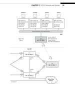
They also introduce a distinctive architecture and terminology, as shown in Figure 26.5.
The fi gure shows a simple two-site arrangement, but the same terms apply to more
complicated confi gurations.
Customer Edge
Each site has a customer-edge (CE) router, designated CE1, CE2, CEn as needed. These
routers are owned and operated by the customer and are at the “edge” of the VPN. At
least one link runs to the ISP and carries customer data to and from the ISP’s network.
The data on the link can be in plain text (the link is generally short, point to point, and
not considered a high security risk) or encrypted with IPSec, SSL, or some other VPN
CHAPTER 26 MPLS-Based Virtual Private Networks 669
protocol. The CEs still run a routing protocol, but only to gather information about
other CE routers belonging to their own L3VPN.
Provider Edge
Each customer site connects to a provider-edge (PE) router, designated PE1, PE2, PEn
as necessary. These are owned and operated by the ISP and are at the provider “edge”
of the VPN. A PE router can carry traffi c to and from many CE routers, and even carry
“regular” Internet traffi c for other customers. These are routers with the VRFs and run
MPLS to the other PE routers and BGP to carry customer routing information. In MPLS
terms, these are the ingress and egress routers, but a PE router on one VPN can be a
transit (P) router on another.
Provider
The provider (P) routers are the MPLS transit routers that carry VPN traffi c through the
provider “core” or backbone. As in MPLS, there must be at least one P router, but there
are usually quite a few, depending on the popularity of the L3VPN service. As with PE
routers, the P routers can carry general ISP traffi c that has nothing to do with VPNs.
The major L3VPN is RFC 4364, and Internet drafts are important for understanding
how MPLS and BGP combine to make an L3VPN. MPLS LSPs connect the PE routers
through the P routers, and BGP is used with route distinguishers to ensure that routing
updates go into the proper VRFs.
The routing tables on the CE routers are generally quite simple. They contain just
a few routes to the other CE router sites and a default for generic Internet access,
which might be through a separate router or through the VPN itself (one tunnel leads
to an Internet router “gateway”). If the Internet access (few VPNs can afford to cut
themselves off from the Internet entirely) is on another router at the customer site, a
fi rewall is typically used to protect this “back door” to the VPN. Firewalls are discussed
in the next chapter.
FIGURE 26.5
Basic MPLS-based VPN architecture and terminology. Note that we’ve been using this terminology
all along.
PEs have VRF for each L3VPN
CE PE PE CE
Internet
MPLS LSP
PEs use BGP to carry VRF routes
P
670 PART VI Security
Layer 2 VPNs
In an L3VPN, the two CE routers are still on two separate networks—just like LAN1 and
LAN2 on the Illustrated Network. CE0 and CE6 use different IP network addresses, such
as 10.0.50.2/24 and 10.0.16.2/24, on their links to PE5 and PE1 toward the network
backbone.
LANs are Layer 2 constructs at heart. Ethernet frames only care about MAC layer
addresses, not IP addresses. Why not just build the VPN at Layer 2 and connect the two
CE routers into one big “virtual” LAN that seems to be as private as both LANs would
be separately? This is the idea behind an L2VPN.
Even though an L2VPN service is delivered over an ISP’s collection of routers (just
like an L3VPN), the end result is much simpler than an L3VPN. This is because there
is no need to maintain separate virtual routing information for each customer. Both
customer routers can use one IP address space (perhaps 10.99.99.0/24), and do not
need to run a routing protocol between the CE routers at all because they appear to be
directly connected and at opposite ends of the same “link.”
The L2VPN architecture still uses the CE-PE-P terminology and uses MPLS LSPs,
but the basic content of the tunnels are Ethernet frames (other “emulated” LANs are
sometimes supported). The backbone routers in an L2VPN are essentially transformed
into LAN bridges. The VPLS tables on the PE routers are now long lists of MAC layer
addresses more similar to ARP caches than to routing tables.
L2VPN service offerings have a variety of names. A popular offering from many ISPs
is some form of virtual private LAN service (VPLS). The LANs are now virtual LANs
(VLANs), and the Ethernet frames between CE and PE routers must employ VLAN tag-
ging to allow the ISP to tell the frames apart at Layer 2. The PE routers are confi gured
with a VPLS virtual port that forms the endpoint of the MPLS tunnel (LSP) that carries
the frames from one LAN to the other.
There are many other variations on the basic VPN types described here. RFC 4026
lists (in addition to L3VPNs, L2VPNs, and VPLS) seven other types of VPN, mostly varia-
tions on the L2VPN theme.
■ Virtual Private Wire Service (VPWS)
■ IP-only LAN-like Service (IPLS)
■ Pseudo Wire (PW)
■ Transparent LAN Service (TLS)
■ Virtual LAN (VLAN)
■ Virtual Private Switched Network (VPSN)
Why all the interest in linking CE routers over Layer 2 through an ISP’s router net-
work? The trend today is to extend Ethernet’s reach and speed to incredible distances
(about 25 miles) and bandwidths (10 Gbps). Some see Ethernet as the ultimate “univer-
sal” network, and one without all the risks inherent in IP-based router networks. How
many malicious users are busily crafting phony Ethernet frames?
Of course, malicious users followed networking from the PSTN (where they were
fi rst active in securing free long-distance service) onto the Internet, and there is no
CHAPTER 26 MPLS-Based Virtual Private Networks 671
reason to think they won’t follow the action anywhere else. But VPNs and virtual LANs
are at least prepared to address security issues from the start.
VPLS: AN MPLS-BASED L2VPN
To make a good confi guration for VPLS, we’ll have to get a little creative with our
network. The two routers attached to LAN1 and LAN2, customer-edge routers CE1 and
CE2, will now support VLAN tagging (not diffi cult to do). With VPLS confi gured, both
LANs still use addresses 10.10.11.0/24 and 10.10.12.0/24. (In other words, we’ll start
the VPLS at the ISP, not at the customer routers—not all users want to renumber all of
their IP devices.)
But now it will look like the CE routers are directly connected with a gigabit
Ethernet LAN sharing a common IP network address. In this example, that address
is 10.99.99.0/24 (which should be distinctive enough to easily pick out). So, this
is where the “virtual LAN” comes in—on the link between CE1 and CE2. We’ve also
merged Best-Ace ISP into one AS (the number is not important) so that we can use
IBGP to distribute the routes and avoid more complex confi gurations.
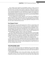
The simplifi ed Illustrated Network confi guration for VPLS, along with interface
designations and IP addresses, is shown in Figure 26.6. The fi gure also shows an
example of the VPLS table on router PE1. This table shows how the MAC addresses
on the interfaces to the CE routers map to MPLS labels instead of IP addresses, as in
an L3VPN.
The VPLS virtual port interfaces on PE1 and PE2 are designated with the vt- (virtual
tunnel) prefi x. These are not physical interfaces on the routers, of course, but logical
interfaces that form the endpoints of the MPLS LSP connecting the routers over the ISP
core backbone. This interface is not confi gured directly, but is the result of the VPLS
confi guration steps.
Router-by-Router VPLS Confi guration
Let’s look at each router individually and show the sections of the confi guration fi les
that directly create the VPLS service between LAN1 and LAN2. Keep in mind that there
could be much more to the confi guration than just these statements.
CE0 Router
All that is needed on the CE0 router is the interface to the PE router and the VLAN iden-
tifi er and IP address associated with it. These values must match the confi guration on
router CE0. (The LAN1 interface is still fe-1/3/0 and is still using 10.10.11.1/24.)
set interfaces ge-0/0/3 vlan-tagging;
set interfaces ge-0/0/3 unit 0 vlan-id 600; # the VLAN ID must must match
throughout the configurations
set interfaces ge-0/0/3 unit 0 family inet address 10.99.99.1/24;
# this address space must match the CE6 link address we use
672 PART VI Security
Interface
LAN1
10.10.11.0/24
LAN2
10.10.12.0/24
PE1:
192.168.1.1
VPLS
ge-0/0/3
10.0.17.1/24
so-0/0/2
10.0.59.2/24
so-0/0/0
VPLS
ge-0/0/3
PE5:
192.168.5.1
PE5 PE1
(P9/
P7)
CE0 CE6
VPLS Virtual Port
MPLS LSP
ge-0/0/3
ge-0/0/3
10.99.99.1/24
ge-0/0/3
10.99.99.2/24
so-0/0/0
10.0.59.1/24
so-0/0/2
10.0.17.2/24
vt-0/3/0:32770 bbbb bbbb bbbb
aaaa aaaa aaaa n/a
n/a
800000 800002
In Label
VPLS Forwarding Table for PE5
MAC Addr Out Label
vt-0/3/0:32771
vt-0/3/0:32770
FIGURE 26.6
Illustrated Network topology for the VPLS confi guration. Note the “new” address space.
PE5 Router
The PE router confi gurations are the most elaborate among the VPLS routers. These
confi gurations are rather lengthy, so comments are used throughout. The PE routers
need BGP, MPLS, OSPF, and RSVP to be confi gured properly for the LSP to work cor-
rectly. RSVP sets up the MPLS LSPs, OSPF handles routine routing chores, and BGP is
used to carry the VPLS MAC layer information between the PE routers.
The PE routers also need to confi gure VLAN tagging and VPLS encapsulation on the
interfaces (physical and logical) to the CE routers. The VLAN ID must match as well, but
no IP address is needed for this “Layer 2” interface. There is a space between major sec-
tions of the confi guration and liberal comments to help track what is being confi gured.
set interfaces ge-0/0/3 vlan-tagging; #interface to CE0
set interfaces ge-0/0/3 encapsulation vlan-vpls;
set interfaces ge-0/0/3 unit 0 encapsulation vlan-vpls;
set interfaces ge-0/0/3 unit 0 vlan-id 600; # must match across the network
set interfaces so-0/0/0 unit 0 family inet address 10.0.59.1; # interface to
P9
set interfaces so-0/0/0 unit 0 family mpls;
CHAPTER 26 MPLS-Based Virtual Private Networks 673
set routing-options autonomous-system 65127;
set routing-options forwarding-table export exp-to-fwd;
# used to distinguish VPLS "routes"
set protocols rsvp interface all; # turn on RSVP
set protocols mpls label-switched-path PE5-to-PE1 to 192.168.1.1;
# The LSP to connect VPLS routers thru loopback addresses
set protocols mpls interface all;
set protocols bgp group vpls-pe type internal;
set protocols bgp group vpls-pe local-address 192.168.5.1;
set protocols bgp group vpls-pe family l2vpn unicast;
# this VPLS is an L2VPN type and only cares about unicast traffic
set protocols bgp group vpls-pe neighbor 192.168.9.1;
# IBGP peer router P9
set protocols bgp group vpls-pe neighbor 192.168.7.1;
# IBGP peer router P7
set protocols bgp group vpls-pe neighbor 192.168.1.1;
# IBGP peer router PE1
set protocols ospf traffic-engineering;
set protocols ospf area 0.0.0.0;
set protocols ospf interface all; # run OSPF to all routers
set policy-options policy-statement exp-to-fwd term A
from community green-community;
# policy to load forwarding table – the community must also match
set policy-options policy-statement exp-to-fwd term A
then install-nexthop lsp PE5-to-PE1;
# makes this LSP the next hop for the VPLS
set policy-options policy-statement exp-to-fwd term A
then accept;
# accepts only community = green-community
set policy-options community green-community;
# sets the community value on BGP routes for the VPLS
set routing-instances green instance-type vpls;
# creates a special forwarding table for VPLS traffic
set routing-instances green interface fe-0/1/0.0;
set routing-instances green route-distinguisher 10.10.10.1;
set routing-instances green vrf-target target:11111:1;
# this value must match the community
set routing-instances green protocols vpls site-range 10;
# this starts the main VPLS configuration
set routing-instances green protocols vpls site greenPE1 site-identifier 1;
# after the protocols, communities, and the rest, this is simple
P Router (P9)
The P routers still need the same BGP, MPLS, OSPF, and RSVP to become a transit router
between PE5 and PE1. But at least no major policies need to be applied or tables created.
The confi guration shown, on P9, is mirrored by the one on P7 (which is not shown).
674 PART VI Security
set interfaces so-0/0/1 unit 0 family inet address 10.0.79.2; # interface to P7
set interfaces so-0/0/1 unit 0 family mpls; #needed for the VPN
set interfaces so-0/0/2 unit 0 family inet address 10.0.59.2; # interface to PE5
set interfaces so-0/0/1 unit 0 family mpls; #needed for the VPN
set protocols rsvp interface all; # turn on RSVP for signaling
set protocols mpls interface all; # turn on MPLS for packet parsing
set protocols bgp group vpls-pe type internal; # create IBGP group for VPLS
set protocols bgp group vpls-pe local-address 192.168.9.1 # P9 router
address
set protocols bgp group vpls-pe family l2vpn unicast # VPLS is for unicast
traffic
set protocols bgp group vpls-pe neighbor 192.168.5.1 # IBGP peer router PE5
set protocols bgp group vpls-pe neighbor 192.168.7.1 # IBGP peer router P7
set protocols bgp group vpls-pe neighbor 192.168.1.1 # IBGP peer router PE1
set protocols ospf traffic-engineering; # needed to divert VPN packets
set protocols ospf area 0.0.0.0 interface all; # run OSPF everywhere
Note that we’ve added the P routers to the IBGP mesh. Technically, the P routers do
not need to be part of the BGP mesh for the VPN, although the P routers might need to
run BGP for other purposes (which is why we are running it here). All that is needed
for the VPN is a full mesh between the PE routers. This confi guration does no harm on
this little network, but when PEs have thousands of VPNs the signaling and information
moved by BGP can create resource issues. In these cases, it is advisable to have a BGP-
free core (unless, of course, BGP is needed on the P routers for other non–VPN-related
purposes).
PE1 Router
The VPLS confi guration on the PE1 router mirrors the confi guration on the PE5 router.
It is shown because of its importance in the VPLS confi guration.
set interfaces ge-0/0/3 vlan-tagging; #interface to CE6
set interfaces ge-0/0/3 encapsulation vlan-vpls;
set interfaces ge-0/0/3 unit 0 encapsulation vlan-vpls;
set interfaces ge-0/0/3 unit 0 vlan-id 600; # must match across the network
set interfaces so-0/0/2 unit 0 family inet address 10.0.17.1; # interface to P7
set interfaces so-0/0/2 unit 0 family mpls;
set routing-options autonomous-system 65127;
set routing-options forwarding-table export exp-to-fwd;
# used to distinguish VPLS "routes"
set protocols rsvp interface all; # turn on RSVP
set protocols mpls label-switched-path PE1-to-PE5 to 192.168.5.1;
# The LSP to connect VPLS routers thru loopback addresses
set protocols mpls interface all;
set protocols bgp group vpls-pe type internal;
set protocols bgp group vpls-pe local-address 192.168.5.1;
CHAPTER 26 MPLS-Based Virtual Private Networks 675
set protocols bgp group vpls-pe family l2vpn unicast;
# this VPLS is an L2VPN type and only cares about unicast traffic
set protocols bgp group vpls-pe neighbor 192.168.9.1;
# IBGP peer router P9
set protocols bgp group vpls-pe neighbor 192.168.7.1;
# IBGP peer router P7
set protocols bgp group vpls-pe neighbor 192.168.5.1;
# IBGP peer router PE5
set protocols ospf traffic-engineering;
set protocols ospf area 0.0.0.0;
set protocols ospf interface all; # run OSPF to all routers
set policy-options policy-statement exp-to-fwd term A
from community green-community;
# policy to load forwarding table – the community must also match
set policy-options policy-statement exp-to-fwd term A
then install-nexthop lsp PE5-to-PE1;
# makes this LSP the next hop for the VPLS
set policy-options policy-statement exp-to-fwd term A
then accept;
# accepts only community = green-community
set policy-options community green-community;
# sets the community value on BGP routes for the VPLS
set routing-instances green instance-type vpls;
# creates a special forwarding table for VPLS traffic
set routing-instances green interface fe-0/1/0.0;
set routing-instances green route-distinguisher 10.10.10.4;
set routing-instances green vrf-target target:11111:1;
# this value must match the community
set routing-instances green protocols vpls site-range 10;
# this starts the main VPLS configuration
set routing-instances green protocols vpls site greenPE1 site-identifier 2;
# after the protocols, communities, and the rest, this is simple
CE6 Router
Finally, the router that connects to LAN2 mirrors the confi guration of the CE0 router.
(The LAN2 interface is still fe-1/3/0 and is still using 10.10.12.1/24.)
set interfaces ge-0/0/3 vlan-tagging;
set interfaces ge-0/0/3 unit 0 vlan-id 600; # the VLAN ID must must match
throughout the configurations
set interfaces ge-0/0/3 unit 0 family inet address 10.99.99.2/24;
# this address space must match the CE0 link address we use
676 PART VI Security
DOES IT REALLY WORK?
Complex confi gurations always pose challenges for verifi cation. How do we know this
VPLS is really working? Well, one way is to see whether the PE routers are learning MAC
addresses.
admin@PE5> show system statistics vpls | match mac
6 mac route learning requests
6 mac router learnt
0 mac routers aged
0 mac router moved
There are many other commands that show VPLS information. But the most impor-
tant information is from the hosts on LAN1 and LAN2 themselves, which now think
their site routers are connected by a single Ethernet LAN instead of six routers.
bsdclient# traceroute 10.10.12.77
traceroute to 10.10.12.77 (10.10.12.77), 64 hops max, 44 byte packets
1 10.10.11.1 (10.10.11.1) 0.419 ms 0.256 ms 0.343 ms
2 10.99.99.2 (10.99.99.2) 0.328 ms 0.294 ms 0.346 ms
3 10.10.12.77 (10.10.12.77) 0.331 ms 0.297 ms 0.346 ms
bsdclient#
The bsdclient and all the other hosts on LAN1 now think that the bsdserver on
LAN2 is only three hops away, although we know there are actually six routers between
the source and destination! The only intermediate address that shows up is the IP
address on the link address on CE6, which is where the MPLS LSP ends.
CHAPTER 26 MPLS-Based Virtual Private Networks 677
This page intentionally left blank