The Illustrated Network- P72 pdf
Bạn đang xem bản rút gọn của tài liệu. Xem và tải ngay bản đầy đủ của tài liệu tại đây (364.92 KB, 10 trang )
QUESTIONS FOR READERS
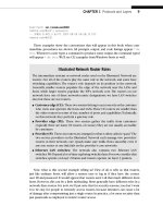
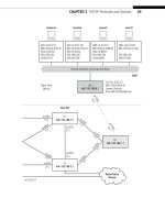
Figure 26.7 shows some of the concepts discussed in this chapter and can be used to
answer the following questions.
1. How many LSPs are used to connect the two routers at the ends of the VPLS?
2. Where does the LSP connecting the site router CE0 to CE6 begin and end?
3. Why is the confi guration on the PE router so complex?
4. What is the function of the VPLS virtual port?
5. What if a third site router using the 10.99.99.2/24 address space joined the
network? Could the VPLS be extended to that site as well? If so, how?
FIGURE 26.7
Topology for the VPLS confi guration.
Interface
LAN1
10.10.11.0/24
LAN2
10.10.12.0/24
PE1:
192.168.1.1
VPLS
ge-0/0/3
10.0.17.1/24
so-0/0/2
10.0.59.2/24
so-0/0/0
VPLS
ge-0/0/3
PE5:
192.168.5.1
PE5 PE1
(P9/
P7)
CE0 CE6
VPLS Virtual Port
MPLS LSP
ge-0/0/3
ge-0/0/3
10.99.99.1/24
ge-0/0/3
10.99.99.2/24
so-0/0/0
10.0.59.1/24
so-0/0/2
10.0.17.2/24
vt-0/3/0:32770 bbbb bbbb bbbb
aaaa aaaa aaaa n/a
n/a
800000 800002
In Label
VPLS Forwarding Table for PE5
MAC Addr Out Label
vt-0/3/0:32771
vt-0/3/0:32770
679
What You Will Learn
In this chapter, you will learn how NAT (originally used to address the shortage of
IPv4 addresses) is now used to conceal public IPv4 addresses. We’ll talk about the
advantages and disadvantages of using NAT for this purpose.
You will learn that there are four types of NAT and fi nd that using NAT for secu-
rity is not the best use of NAT. We’ll also confi gure the popular NATP and see how
and where the IPv4 addresses on the Illustrated Network are translated.
Network Address
Translation
27
This chapter deals with a common TCP/IP practice, network address translation (NAT).
NAT is used to conceal the true public IPv4 addresses of a device by using substitute
IPv4 addresses in packet headers. NAT is usually performed by customer-edge (site)
routers or hubs, and is more sophisticated today than the older methods of simply
using private RFC 1918 addresses whenever one liked.
Although often presented as a security feature, NAT (properly called “IP NAT” because
there are many types of network addresses that can be translated) was invented in RFC
1631 to address the shortage of IPv4 addresses while the world waited for IPv6. NAT is
still not an offi cial Internet standard, but it is a very common practice and a feature of
many routers, hubs, and remote access devices.
When NAT was introduced, it was immediately embraced to address the simple
fact that IPv4 addresses were limited. Any organization that had only a Class C address
(back then) would be attracted to a way to allow more than 250 or so devices to access
the Internet at the same time.
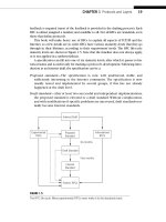
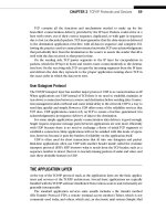
In this chapter, we’ll be using the equipment shown in Figure 27.1. We’ll confi g-
ure the CE0 at the edge of the network router to do NAT for the clients on LAN1
(bsdclient and wincli1). Before we confi gure NAT, we’ll have to explore all of the
types of NAT we could use and then confi gure one of these types for LAN1.
CE0
lo0: 192.168.0.1
fe-1/3/0: 10.10.11.1
MAC: 00:05:85:88:cc:db
(Juniper_88:cc:db)
IPv6: fe80:205:85ff:fe88:ccdb
P9
lo0: 192.168.9.1
PE5
lo0: 192.168.5.1
P4
lo0: 192.168.4.1
so-0/0/1
79.2
so-0/0/1
24.2
so-0/0/0
47.1
so-0/0/2
29.2
so-0/0/3
49.2
so-0/0/3
49.1
so-0/0/0
59.2
so-0/0/2
45.1
so-0/0/2
45.2
so-0/0/0
59.1
ge-0/0/3
50.2
ge-0/0/3
50.1
DSL Link
Ethernet LAN Switch with Twisted-Pair Wiring
bsdclient lnxserver wincli1
em0: 10.10.11.177
MAC: 00:0e:0c:3b:8f:94
(Intel_3b:8f:94)
IPv6: fe80::20e:
cff:fe3b:8f94
eth0: 10.10.11.66
MAC: 00:d0:b7:1f:fe:e6
(Intel_1f:fe:e6)
IPv6: fe80::2d0:
b7ff:fe1f:fee6
LAN2: 10.10.11.51
MAC: 00:0e:0c:3b:88:3c
(Intel_3b:88:3c)
IPv6: fe80::20e:
cff:fe3b:883c
LAN2: 10.10.11.111
MAC: 00:0e:0c:3b:87:36
(Intel_3b:87:36)
IPv6: fe80::20e:
cff:fe3b:8736
winsvr1
LAN1
Los Angeles
Office
Wireless
in Home
AS 65459
Solid rules ϭ SONET/SDH
Dashed rules ϭ Gig Ethernet
Note: All links use 10.0.x.y
addressing only the last
two octets are shown.
Best
-
FIGURE 27.1
NAT on the Illustrated Network showing NAT confi gured on CE0 for the use of two hosts on LAN1.
682 PART VI Security
CE6
lo0: 192.168.6.1
fe-1/3/0: 10.10.12.1
MAC: 0:05:85:8b:bc:db
(Juniper_8b:bc:db)
IPv6: fe80:205:85ff:fe8b:bcdb
Ethernet LAN Switch with Twisted-Pair Wiring
bsdserver lnxclient winsvr2 wincli2
eth0: 10.10.12.77
MAC: 00:0e:0c:3b:87:32
(Intel_3b:87:32)
IPv6: fe80::20e:
cff:fe3b:8732
eth0: 10.10.12.166
MAC: 00:b0:d0:45:34:64
(Dell_45:34:64)
IPv6: fe80::2b0:
d0ff:fe45:3464
LAN2: 10.10.12.52
MAC: 00:0e:0c:3b:88:56
(Intel_3b:88:56)
IPv6: fe80::20e:
cff:fe3b:8856
LAN2: 10.10.12.222
MAC: 00:02:b3:27:fa:8c
IPv6: fe80::202:
b3ff:fe27:fa8c
LAN2
New York
Office
P7
lo0: 192.168.7.1
PE1
lo0: 192.168.1.1
P2
lo0: 192.168.2.1
so-0/0/1
79.1
so-0/0/1
24.1
so-0/0/0
47.2
so-0/0/2
29.1
so-0/0/3
27.2
so-0/0/3
27.1
so-0/0/2
17.2
so-0/0/2
17.1
so-0/0/0
12.2
so-0/0/0
12.1
ge-0/0/3
16.2
ge-0/0/3
16.1
AS 65127
Global Public
Internet
Ace ISP
CHAPTER 27 Network Address Translation 683
USING NAT
With NAT, a network could support 500 or so hosts with private addresses, and the NAT
router could translate these to the public IP address range when the client needed Inter-
net access. After all, the remote server replied blindly to the source IP address, which
only needed to be routable and not private. NAT devices could even allow ports to be
part of the process (and know that a server’s reply to 10.10.11.177:30567 is different
from a reply to 10.10.11.177:31420), even though the IP addresses were the same.
Many DSL access devices (“DSL routers”) still use this “trick” to allow multiple home
computers to share a single IP address from the ISP. Many ISPs are careful to point out
that this arrangement is often not supported, which always boils down to two things:
They won’t tell you how to confi gure it and you can’t report a problem on it if you do
confi gure it and it doesn’t work. Modern NAT devices know which addresses belong to
servers (and should be translated consistently so that clients can fi nd them, or not be
translated at all) and which are clients (and can be changed with abandon).
NAT and IPv6
Why does this chapter only talk about NAT and IPv4? What happened to IPv6?
What happened is that RFC 4864 released in May 2007 contained more than
30 pages in which it was patiently explained that NAT is not a security feature (as
pointed out in this chapter) and should be thought of solely as a way to extend the
availability of IPv4 address space. Once the huge address space in IPv6 is available,
there is no need for NAT.
RFC 4864 points out that everything NAT does can be done in IPv6 without
any additional protocols. These native IPv6 features include the use of privacy
addresses (RFC 3041), unique local addresses (ULAs, as described in RFC 4193),
the use of DHCPv6, and so on. In other words, they are things that we have already
talked about which can enable internal addressing masking from the global net-
work. For these reasons, as well as the limitations of space, we will not deal with
IPv6 in this chapter.
Advantages and Disadvantages of NAT
Today, NAT still offers advantages, but these often have to be balanced against some
disadvantages, especially when coupled with current security practices. The advan-
tages to using NAT follow:
Address sharing—A small number of IP addresses can support a larger pool of
devices.
Ease of expansion—If the number of hosts grows beyond the public IPv4 space
assigned, it’s easy to add hosts.
684 PART VI Security
Local control—Administrators essentially run their own private piece of the
public Internet.
Easy ISP changeover—When host addresses are private, public ISP addresses can
be changed more easily.
Mainly transparent—Usually, only a handful of devices have to know the NAT
rules for a site.
Security—Oversold, but still seen as an advantage. Hackers don’t know the “real”
client’s IP address, true, but the true targets are often servers and the NAT
“firewalls” themselves.
These NAT pluses have to be balanced against the current list of disadvantages.
Complexity—NAT adds management complexity and makes even routine trouble-
shooting more difficult.
Public address sensitivity—Private addresses are favored by hackers. Some appli-
cations and devices raise flags when presented with private addresses. (One
FTP application used for this book insisted on needing to know the “real”
public network IP address of the host before it would work properly!)
Application compatibility issues—NAT is not totally transparent. Applications
such as FTP, which embed IP addresses and port numbers in data (such as
the PASV and PORT messages), must be handled with special care by NAT
routers.
Poor host accessibility—NAT makes it difficult to contact local devices from the
outside world. NAT is not a good solution for Web sites, FTP servers, or even
peer protocols (VoIP) running on a local LAN.
Performance concerns—The burden of hundreds of simultaneous Internet access
users today often degrades NAT router performance for its main task: routing
packets.
Security—Both a plus and a minus. Modern protocols such as IPSec raise alarms
when packet fields are changed between end systems. You can still combine
NAT and IPsec (carefully), but keeping NAT as a “security feature” in addition
to IPSec can be tricky.
Four Types of NAT
NAT is still a popular thing to do on a network. There are even the following four
slightly different versions of NAT that are supported in many routers, and most are
known by a number of unoffi cial names.
CHAPTER 27 Network Address Translation 685
■ Unidirectional NAT (outbound or “traditional” NAT)
■ Bidirectional NAT (inbound or “two-way” NAT)
■ Port-based (“overloaded” NAT, or NAPT or PAT)
■ Overlapping NAT (“twice NAT”)
All of these methods are a little different, but all involve use of the same terms to
describe the addresses that are translated. An address can be inside or outside, based
on whether it is used on the local LAN (inside) or on the Internet (outside). Addresses
can also be local or global, based on whether they are drawn from the private RFC 1918
address ranges (local) or publicly registered or obtained from an ISP (global).
NAT therefore encompasses about four address “types,” which are listed in
Table 27.1. In the table, the Martian address ranges 169.254.0.0/16 (used for IPv4 auto-
confi guration) and 250.0.0./8 (experimental) are used as “public” addresses to pre-
serve the Illustrated Network’s policy of never using public IP addresses as examples.
In addition, the translational mappings that NAT performs can be static or dynamic.
Static translations establish a fi xed relationship between inside and outside addresses,
whereas dynamic mappings allow this relationship to change between one translation
and another. These can be mixed, using static mapping for servers (for example) and
dynamic for clients, much like DHCP. DNS can be used for NAT purposes as well. Let’s
look at how each NAT variation uses these address translation terms and procedures.
Table 27.1 Address Types Used in NAT with Chapter’s Example Values
Type of Address Example Common Use
Inside local 10.100.100.27 Client’s “native” address used as source in outbound
packets and destination inbound
Outside local 172.16.100.13 Destination address used by client
Inside global 169.254.99.1 Client’s public address, range assigned by ISP
Outside global 250.99.111.4 Source and destination address used on Internet
Unidirectional NAT
Let’s examine an example for outbound or traditional NAT that will repeat addresses
from one NAT type to the other as we show how they differ. Assume that the LAN
has 250 hosts that use private (inside local) addresses in the 10.100.100.0/24 range.
These hosts use dynamic NAT to share a pool of 20 inside global addresses in the range
169.254.99.1 through 169.254.99.20.
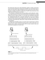
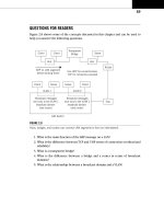
Suppose client host 10.100.100.27 accesses the Web server at public address
250.99.111.4 using unidirectional NAT. What will the router do to the packet addresses
and what will the addresses look like at each step along the way—inside to NAT, NAT to
outside, outside to NAT, and NAT to inside? Figure 27.2 shows the four steps.
686 PART VI Security
The client’s packet to the server at 250.99.111.4 has its source address changed from
10.100.100.27 (inside private) to 169.254.99.1 (outside global, which must be a routable
address). The server replies by swapping source and destination address, and the reply
(matching up in the NAT device to the request) is translated back to 10.100.100.27.
No one outside the organization knows which host “really” has address 10.100.100.27,
although dynamic NAT is better at this concealment than a static NAT mapping.
It might seem that dynamic mapping would always be the proper NAT choice. How-
ever, a complication arises when there are two site routers (as is often the case). If the
request is sent by one NAT router and the reply received by another NAT router, the
translation tables must be the same or chaos will result. Unless the routers constantly
communicate NAT information (how?), this makes it diffi cult to use dynamic mapping.
NAT also handles adjustments other than address translation. The IP checksum must
be changed, as well as UPD/TCP checksums. FTP embeds address and port information
in data, and these should be changed as well. Finally, ICMP messages include initial
header bytes, and even these should be changed when an ICMP message is the reply
to a request.
Traditional NAT only handles this type of outbound translation. It cannot handle
requests from a device on the public Internet to access a server on the private
network (LAN).
Bidirectional NAT
Let’s use the same basic scenario that we employed in the unidirectional NAT example,
but upgrade the NAT router to use inbound or two-way NAT. The major difference is
that bidirectional NAT allows requests to be initiated from the global public Internet to
hosts on the private inside LAN.
“Inside” LAN “Outside” Internet
Host
Host
NAT
Device
Request
Dest: 250.99.111.4
Source: 10.100.100.27
Reply
Dest: 10.100.100.27
Source: 250.99.111.4
Reply
Dest: 169.254.99.1
Source: 250.99.111.4
10.100.100.27
Request
Dest: 250.99.111.4
Source: 169.254.99.1
4. NAT on destination 3. Server sends reply
1. Client sends request 2. NAT on source address
250.99.111.4
FIGURE 27.2
Unidirectional NAT. Note that only the LAN source address is translated, and in one direction.
CHAPTER 27 Network Address Translation 687
This type of NAT is more diffi cult to implement because, whereas inside users
generally know the public addresses of Internet devices, outside devices have no idea
what private addresses represent the device on the LAN. And even if they did know
them, private RFC 1918 addresses are not routable, so there would be no way to get a
packet there anyway. (Home DSL routers, which normally all use NAT by default, have
led to an explosion of
10.0.0.0/8 and 192.168.0.0/16 devices around the world—yet
another reason ISPs refuse to support home servers unless covered by the service
offering.)
Static NAT mapping, one for one from local device to public address, is one way to
handle the “outside request” issue. Of course, this defeats the more-than-public-address-
space support that NAT offers, and makes any security claims hollow. (Packets are
blindly forwarded to the target anyway.)
The other solution is to use DNS. As long as the outside request is by name and not
IP address, DNS can provide the current private global address of the host (it must be
global because it must be routable). In other words, DNS and NAT can work together
(as described in RFC 2694), which adds extensions for NAT to DNS. This solution uses
dynamic NAT and is a four-step process. The outside client sends a request to DNS to
get the IP address that goes, for instance, with www.natusedhere.com.
The authoritative DNS server for the natusedhere.com domain resolves the name
into an inside local (private) address for the host, perhaps 10.100.100.27, as before. The
inside local address is now sent to the local NAT device to create a dynamic mapping
between this private address and an inside global (public and routable) address. This
mapping is used in the NAT translation table. For this example, we’ll use 169.254.99.1,
as before.
“Inside” LAN “Outside” Internet
Host
Host
NAT
Device
Request
Dest: 10.100.100.27
Source: 250.99.111.4
Reply
Dest: 250.99.111.4
Source: 10.100.100.27
Reply
Dest: 250.99.111.4
Source: 169.254.99.1
10.100.100.27
Request
Dest: 169.254.99.1
Source: 250.99.111.4
3. Server sends reply 4. NAT on source
2. NAT on destination
1. Client sends request
250.99.111.4
FIGURE 27.3
Bidirectional NAT, showing the direction in reverse from the previous fi gure. Note the reversal
of number sequence and initiating client location.
688 PART VI Security