Troubleshooting and Repair of Diesel Engines P2 pot
Bạn đang xem bản rút gọn của tài liệu. Xem và tải ngay bản đầy đủ của tài liệu tại đây (562.95 KB, 20 trang )
To get around this restriction, many diesels incorporate an air pump in the form
of an exhaust-driven turbocharger or a mechanical supercharger. Forced induction
can double power outputs without violating the smoke limit. And, as far as tur-
bochargers are concerned, the supercharge effect is free. That is, the energy that drives
the turbo would otherwise be wasted out the exhaust pipe as heat and exhaust-gas
velocity.
The absence of an air restriction and an ignition system that operates as a func-
tion of engine architecture can wrest control of the engine from the operator. All
that’s needed is for significant amounts of crankcase oil to find its way into the com-
bustion chambers. Oil might be drawn into the chambers past worn piston rings or
from a failed turbocharger seal. Some industrial engines have an air trip on the intake
manifold for this contingency, but many do not. A runaway engine generally accel-
erates itself to perdition because few operators have the presence of mind to engage
the air trip or stuff a rag into the intake.
Ignition and combustion
SI engines are fired by an electrical spark timed to occur just before the piston
reaches the top of the compression stroke. Because the full charge of fuel and air is
present, combustion proceeds rapidly in the form of a controlled explosion. The rise
in cylinder pressure occurs during the span of a few crankshaft degrees. Thus, the
cylinder volume above the piston undergoes little change between ignition and peak
pressure. Engineers, exaggerating a bit, describe SI engines as “constant volume”
engines (Fig. 2-4).
Compared to SI, the onset of diesel ignition is a leisurely process (Fig. 2-4). Some
time is required for the fuel spray to vaporize and more time is required for the spray
to reach ignition temperature. Fuel continues to be injected during the delay period.
Once ignited, the accumulated fuel burns rapidly with correspondingly rapid
increases in cylinder temperature and pressure. The injector continues to deliver fuel
through the period of rapid combustion and into the period of controlled combustion that
follows. When injection ceases, combustion enters what is known as the afterburn period.
The delay between the onset of fuel delivery and ignition (A–B in Fig. 2-5)
should be as brief as possible to minimize the amount of unburnt fuel accumulated
in the cylinder. The greater the ignition lag, the more violent the combustion and
resulting noise, vibration, and harshness (NVH).
Ignition lag is always worst upon starting cold, when engine metal acts as a heat
sink. Mechanics sometimes describe the clatter, white exhaust smoke, and rough
combustion that accompany cold starts as “diesel detonation,” a term that is mis-
leading because diesels do not detonate in the manner of SI engines. Combustion
should smooth out after the engine warms and ignition lag diminishes. Heating the
incoming air makes cold starts easier and less intrusive.
In normal operation, with ignition delay under control, cylinder pressures and
temperatures rise more slowly (but to higher levels) than for SI engines. In his pro-
posal of 1893, Rudolf Diesel went one step further and visualized constant pressure
expansion: fuel input and combustion pressure would remain constant during the
Ignition and combustion 13
expansion, or power, stroke. He was able to approach that goal in experimental
engines, but only if rotational speeds were held low. His colleagues eventually aban-
doned the idea and controlled fuel input pragmatically, on the basis of power output.
Even so, the pressure rise is relatively smooth and diesel engines are sometimes
called “constant pressure” devices to distinguish them from “constant volume” SI engines
(shown back at Fig. 2-4).
14 Diesel basics
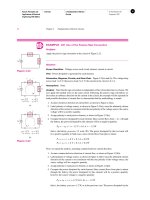
2-4 These cylinder pressure/volume diagrams distort reality somewhat, but indicate why
SI engines are described as “constant volume” and CI as “constant pressure.”
2-5 Diesel combustion and compression pressure rise plotted against
crankshaft rotation.
Two- and four-stroke-cycle
CI and SI engines operate on similar cycles, consisting of intake, compression,
expansion, and exhaust events. Four-stroke-cycle engines of either type allocate one
up or down stroke of the piston for each of the four events. Two-stroke-cycle
engines telescope events into two strokes of the piston, or one per crankshaft revo-
lution. In the United States, the term stroke is generally dropped and we speak of
two- or four-cycle engines; in other parts of the English-speaking world, the pre-
ferred nomenclature is two-stroke and four-stroke.
Four-cycle diesel engines operate as shown in Fig. 2-6. Air, entering around the
open intake valve, fills the cylinder as the piston falls on the intake stroke. The intake
valve closes as the piston rounds bdc on the compression stroke. The piston rises,
compressing and heating the air to ignition temperatures.
Injection begins near tdc on the compression stroke and continues for about 40°
of crankshaft rotation. The fuel ignites, driving the piston down in the bore on the
expansion, or power stroke. The exhaust valve opens and the piston rises on the
exhaust stroke, purging the cylinder of spent gases. When the piston again reaches
tdc, the four-stroke-cycle is complete, two crankshaft revolutions from its beginning.
Figure 2-7 illustrates the operation of Detroit Diesel two-cycle engines, which
employ blower-assisted scavenging. As shown in the upper left drawing, pressurized
air enters the bore through radial ports and forces the exhaust gases out through the
Two- and four-stroke-cycle 15
Air intake valve
Intake stroke Compression stroke Expansion stroke Exhaust stroke
Piston Cylinder liner
Exhaust valve
Fuel injection valve
2-6 Four-cycle operation. Yanmar Diesel Engine Co. Ltd.
cylinder without raising its pressure much above atmospheric. The exhaust valve
remains open until the ports are closed to eliminate a supercharge effect.
The exhaust valve then closes and the piston continues to rise, compressing the
air charge ahead of it. Near tdc, the injector fires, combustion begins, and cylinder
pressure peaks as the piston rounds tdc. Expanding gases drive the piston down-
ward. The exhaust valve opens just before the scavenge ports are uncovered to give
spent gases opportunity to blow down. These four events—intake, compression,
expansion, and exhaust—occur in two piston strokes, or one crankshaft revolution.
Not all two-cycle diesel engines have valves. Combining scavenge air with com-
bustion air eliminates the intake valve, and a port above the air inlet port replaces
the exhaust valve. Such engines employ cross-flow or loop scavenging (Fig. 2-8) to
16 Diesel basics
2-7 Two-cycle operation. The Detroit Diesel engine depicted here
employs a Roots-type positive-displacement blower for scavenging.
purge the upper reaches of the cylinder and to minimize the loss of scavenge air to
the exhaust. In the cross-flow scheme, a deflector cast into the piston crown diverts
the incoming air stream away from the open exhaust port and into the stagnant
region above the piston. The angled inlet ports on loop-scavenged engines produce
the same effect.
It is also possible to eliminate the external air pump by using the crankcase as
part of the air inlet tract. Piston movement provides the necessary compression to
pump the air, via a transfer port, into the cylinder. Not many crankcase-scavenged
engines are seen in this country, but the German manufacturer Fichtel & Sachs has
built thousands of them.
Because two-cycle engines fire every revolution, the power output should be
twice that of an equivalent four-stroke. Such is not the case, principally because of
difficulties associated with scavenging. Four-cycle engines mechanically purge
exhaust gases, through some 440° of crankshaft revolution. (The exhaust valve opens
Two- and four-stroke-cycle 17
2-8 Cross-flow scavenging employs a deflector on the piston crown to divert
the incoming air charge up and away from the exhaust port. Loop scavenging
achieves the same effect with angled inlet ports.
early during the expansion stroke and closes after the intake valve opens). Two-
cycles scavenge in a less positive manner during an abbreviated interval of about 130°
Consequently, some exhaust gas remains in the cylinder to dampen combustion.
Power and torque
Horsepower is the ability to perform work over time. In 1782, James Watt, a pio-
neer developer of steam engines, observed that one mine pony could lift 550 lb of
coal one foot in one minute. Torque is the instantaneous twisting force applied to
the crankshaft. In the English-speaking world, we usually express torque as pounds
of force applied on a lever one foot long.
The two terms are related:
Horsepower ϭ torque ϫ 2pi ϫ rpm. Revolutions per minute is the time component.
Torque ϭ displacement ϫ 4pi ϫ bmep. The latter term, brake mean effective
pressure, is the average pressure applied to the piston during the expansion stroke.
High-performance diesels, such as used in European automobiles, develop max-
imum horsepower at around 5000 rpm. Equivalent SI auto engines can turn almost
twice as fast. Since rpm is part of the hp formula, these diesels fall short in the power
department. An SI-powered car will have a higher top speed.
But, thanks to high effective brake mean pressures, diesels have the advantage
of superior torque. A diesel-powered BMW or Mercedes-Benz easily out-accelerates
its gasoline-powered cousins.
Fuel efficiency
High c/r’s (or more exactly, large ratios of expansion) give CI engines superior
thermal efficiency. Under optimum conditions, a well-designed SI engine utilizes
about 30% of the heat liberated from the fuel to turn the crankshaft. The remainder
goes out the exhaust and into the cooling system and lubricating oil. CI engines
attain thermal efficiencies of 40% and greater. By this measure—which is becoming
increasingly critical as fears about global warming are confirmed—diesel engines are
the most efficient practical form of internal combustion. (Gas turbines do better, but
only at constant speeds.)
Excellent thermal efficiency, plus the volumetric efficiency afforded by an
unthrottled intake manifold and the ability to recycle some exhaust heat by tur-
bocharging, translate into fuel economy. It is not unreasonable to expect a specific
fuel consumption of 0.35 lb/hp-hr from a CI engine operating near its torque peak.
An SI engine can consume 0.50 lb/hp-hr under the same conditions.
The weight differential between diesel fuels (7.6 lb/US gal for No. 2D) and gaso-
line (about 6.1 lb/US gal) gives the diesel an even greater advantage when con-
sumption is figured in gallons per hour or mile. CI passenger cars and trucks deliver
about 30% better mileage than the same vehicles with gasoline engines.
Diesel pickups and SUVs appeal in ways other than fuel economy. Owners of
these vehicles tend to become diesel enthusiasts. I’m not sure why, but it probably
18 Diesel basics
has something to do with the sheer mechanical presence that industrial products
radiate. Earlier generations had the same sort of love affair with steam.
Weight
The Cummins ISB Dodge pickup motor weighs 962 lb and develops 260 hp for
a wt/hp ratio of 3.7:1. The 500-hp Caterpillar 3406E, a standard power plant for large
(Grade-8) highway trucks comes in at 5.7 lb/hp. The Lugger, a marine engine of leg-
endary durability, weighs 9.6 lb for each of its 120 horses. By comparison, the
Chevrolet small block SI V-8 has an all-up weight of about 600 lb and with a bit of
tweaking develops 300 hp.
Much of the weight of diesel engines results from the need to contain combus-
tion pressures and heat that, near tdc, peak out at around 1000 psi and 3600°F. And,
as mentioned earlier, bmep, or average cylinder pressures, are twice those of SI
engines.
There are advantages to being built like a Sumo wrestler. Crankshaft bearings
stay in alignment, cylinder bores remain round, and time between overhauls can
extend for tens of thousands of hours.
Durability
Industrial diesel engines come out of a conservative design tradition. High ini-
tial costs, weight, and moderate levels of performance are acceptable tradeoffs
against early failure. The classic diesel is founded on heavy, fine-grained iron cast-
ings, liberally reinforced with webbing and aged prior to machining. Buttressed
main-bearing caps, pressed into the block and often cross-drilled, support the crank-
shaft. Pistons run against replaceable liners, whose metallurgy can be precisely con-
trolled. Some of the better engines, such as the Cummins shown in Fig. 2-9, feature
straight-cut timing gears, which are virtually indestructible.
Until exhaust gas recirculation became the norm, heavy truck piston rings could, on
occasion, go for a million miles between replacements. An early Caterpillar 3176 truck
engine was returned to the factory for teardown after logging more than 600,000 miles.
Main and connecting-rod bearings had been replaced (at 450,000 and 225,000 miles,
respectively) and were not available for examination. The parts were said to be in good
condition.
The crankshaft remained within tolerance, as did the rocker arms, camshaft jour-
nals, and lower block casting. Valves showed normal wear, but were judged reusable.
Connecting rods could have gone another 400,000 miles and pistons for 200,000
miles. The original honing marks were still visible on the cylinder liners.
But Caterpillar was not satisfied, and has since made a series of major revisions
to the 3176, including redesigned pistons, rings, connecting rods, head gasket,
rocker shafts, injectors, and water pump. Crankshaft rigidity has been improved, and
tooling developed to give the cylinder liners an even more durable finish.
Durability 19
Durability is not a Caterpillar exclusive: according to the EPA, heavy-truck
engines have an average life cycle of 714,000 miles. Not a few Mercedes passenger
cars have passed the three-quarter-million mile mark with only minor repairs.
This is not to say that diesels are zero-defect products. Industrial engines are less
than perfect, and when mated with digital technology the problems multiply. Many
of the worst offenders are clones, that is, diesels derived from existing SI engines.
No one who was around at the time can forget the 1978 Oldsmobile Delta 88 Royale
that sheared head bolts, crankshafts, and almost everything in between. Another
clone that got off to a bad start was the Volkswagen. Like the Olds, it had problems
with fasteners and soft crankshafts. But these difficulties were overcome. Today the
VW TDi is the most popular diesel passenger-car engine in Europe, accounting for
40% of Volkswagen’s production.
Conventional fuels
Diesel fuel is a middle distillate, slightly heavier than kerosene or jet fuel.
Composition varies with the source crude, the refining processes used, the additive
mix, and the regulatory climate. ASTM (American Society for Testing Materials)
norms for Nos. 1-D and 2-D fuels in the United States are shown in Table 2-1.
Table 2-2 lists characteristics the EPA considers typical for Nos. 1-D and 2-D ULSD
sold outside of California, which has its own, more rigorous rules. Note that EPA reg-
ulations apply only to sulfur content and to cetane number/aromatic content. Other
20 Diesel basics
2-9 The Cummings ISB employs straight-cut timing gears that, while noisy, are practically
indestructible. Gilmer-type toothed timing belts, typical of passenger-car diesels, need
replacement at 60,000 miles or less.
fuel qualities, such as lubricity, filterability, and viscosity, are left to the discretion of
the refiner. As a general rule, large truck stops provide the best, most consistent fuel.
• Cetane number (CN) and aromatic content refer to the ignition quality of
the fuel. U.S. regulations permit 40 CN fuel if the aromatic content does not
exceed 35%. In Europe diesel fuel must have a CN of at least 51. Aromatic
content expresses the ignition quality of the fuel. High-octane fuels, such as
aviation gasoline, have low CNs and barely support diesel combustion.
Conversely, ether and amyl nitrate, which detonate violently in SI engines,
are widely used as diesel starting fluids.
• API (American Petroleum Institute) gravity is an index of fuel density and,
by extension, its caloric value. Heavier fuels produce more energy per
injected volume.
• Viscosity also affects performance. Less viscous fuels atomize better and
produce less exhaust smoke. But extremely light fuel upsets calibration by
leaking past pump plungers. Thick, highly viscous fuels increase delivery
pressures and pumping loads.
• Flash point, or the temperature at which the fuel releases ignitable vapors,
is a safety consideration.
Conventional fuels 21
Table 2-1. ASTM diesel fuel grades
Grade Characteristics Sulfur content
No. 1-D S15 ULSD ULSD is mandatory for use on all 2007-model 15 ppm
(ultra-low sulfur diesel) and later road vehicles. Because of its high
volatility No. 1-D ULSD is sometimes
substituted for No. 2-D ULSD in cold
climates.
No. 1-D S500 Obsolete and in process of phase-out. 500 ppm
Damages emission control equipment on
2007 and later model vehicle engines
No. 2-D S15 ULSD The standard fuel for vehicles and other small, 15 ppm
high-speed engines. Produces slightly more
power than No. 1-D ULSD
No. 2-D S500 Obsolete and in process phase-out. Damages 500 ppm
emission control equipment on 2007 and
later model vehicle engines.
Table 2-2. ULSD fuel characteristics
No. 1D No. 2D
Cetane number 40–54 40–50
Gravity, ºAPI 40–44 32–37
Sulfur, ppm 7–15 7–15
Min. aromatics, % 8 27
Min. flashpoint, ºF 120 130
Viscosity, centistokes 1.6–2.0 2.0–3.2
This page intentionally left blank
23
3
CHAPTER
Engine installation
This chapter describes power requirements, mounting provisions, and alignment
procedures for installing diesel engines in motor vehicles, stationary applications,
and small boats. What I have tried to do here is to provide information that does not
have wide currency, but is so critical that it makes or breaks the installation. Vendor
catalogs serve for other aspects of the job, such as radiator/keel cooler sizing, selec-
tion of anti-vibration mounts, and sound-proofing techniques.
Trucks and other motor
vehicles
Normally, installation is a bolt-on proposition, but things become complex when
engines or transmissions are not as originally supplied.
Power requirements
Operators often judge a truck’s power, or lack of it, by how fast the truck runs. In
other words, operators look at maximum rated horsepower available at full governed
rpm. But expected road speeds may be unrealistic. For example, numerically low axle
ratios can, up to a point, increase top speed, but at the cost of reduced acceleration
and less startability, a term that is defined below. Other factors that influence top
speed are loaded weight, road conditions, wind resistance (which can double when
loads are carried outside of the vehicle bodywork), and altitude. Naturally aspirated
engines lose about 3% of their rated power per 1000 ft of altitude above sea level.
The desired cruising speed should be 10% to 20% below rated horsepower rpm,
to provide a reserve of power for hill climbing and passing. When fuel economy is
a primary consideration, the cruising speed can be set even lower. The power
required at cruising speed is the engine’s net horsepower.
Other factors to consider are the ability of the vehicle to cope with grades.
Startability is expressed as the percentage grade the vehicle can climb from a dead
stop. A fully loaded general-purpose truck should be able to get moving up a 10%
Copyright © 2008, 1995, 1991, 1975 by Paul Dempsey. Click here for terms of use.
24 Engine installation
grade in low gear. Off-road vehicles should be able to negotiate 20% grades, with
little or no clutch slippage. Startability is a function of the lowest gear ratio and the
torque available at 800–1000 rpm.
Gradeability is the percentage grade a truck can climb from a running start while
holding a steady speed. No vehicle claiming to be self-propelled should have a
gradeability of less than 6%. Gradeability depends upon maximum torque the engine
is capable of multiplied by intermediate gearing.
Caterpillar and other engine manufacturers can provide assistance for sizing the
engine to the particular application. But it’s useful to have some understanding of
how power requirements are calculated.
The power needed to propel a vehicle is the sum of driveline losses, air resis-
tance, rolling resistance, and grade resistance.
driveline losses ϭ 1 Ϫ driveline eff. ϫ hp
air
ϩ hp
roll
ϩ hp
grade
driveline eff. ϭ overall efficiency of the driveline, calculated on the assumption
that each driven element—main transmission, auxiliary transmission, and rear axle—
imposes an efficiency penalty of 4%. Thus, a truck with a single transmission and one
driven rear axle would have an overall driveline efficiency of 92% (0.96 ϫ 0.96 ϭ 92%).
hp
air
ϭ air resistance hp ϭ (mph
3
Ϭ 375) ϫ 0.00172 ϫ modifier ϫ frontal area
Without some sort of provision to smooth airflow, the truck has a modifier of
1.0. If an aerodynamic device is fitted, the modifier is 0.60. For purposes of our cal-
culation, frontal area ϭ width in feet ϫ (height in feet Ϫ 0.75 ft).
hp
roll
ϭ rolling resistance hp ϭ GVW ϫ mph ϫ Crr
where GVW represents the gross vehicle weight in pounds, and Crr represents the rolling
resistance. This latter figure depends upon tire type: on smooth concrete, bias-ply tires
have a Crr of 17 lb/ton and radial tires 11 lb/ton. Low-profile tires do even better.
hp
grade
ϭ grade hp ϭ (grade percentage ϫ GVW ϫ mph) Ϭ 37,500
Motor mounts
In most instances, the technician merely bolts the engine down to a factory-designed
mounting system. But there are times when engine-mounting provisions cannot be
taken for granted.
Vehicle engines traditionally use a three-point mounting system, with a single
point forward around which the unit can pivot, and with two points at the flywheel
housing or transmission. For some engines the forward mount takes the form of an
extension, or trunnion, at the crankshaft centerline. A sleeve locates the trunnion lat-
erally, while permitting the engine to rotate. In order to simplify mounting and give
more control over resiliency, other engines employ a rigid bracket bolted to the timing
cover and extending out either side to rubber mounts on the frame.
Rear mounts normally bolt to the flywheel cover and function to locate the engine
fore and aft, while transmitting the torque reaction to the vehicle frame. In order to
control vibration, mount stiffness must be on the order of one-tenth of frame stiffness.
On many applications the transmission cantilevers off the engine block without
much additional support. The bending moment imposed by the overhung load on
the flywheel housing should be calculated and compared against factory specs for
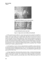
the engine. Figure 3-1 illustrates the calculation for a transmission that receives some
additional support at the rear with a third mount.
The third mount should have a vertical rate (lb/in. of deflection) considerably
lower than the vertical rate of the rear engine mounts. A transmission mount with a
higher spring rate than the engine mounts increases the bending moment. In addi-
tion, the high spring rate is almost sure to deflect the truck frame and, in the process,
generate high forces on the engine/transmission package.
Off-road trucks present special problems, since engines and transmissions are sub-
ject to high gravity loads and the potential for frame distortion. Another factor that needs
to be taken into consideration is that motor mounts must be able to absorb the torque
reactions generated by the ultra-low gear ratios often specified for these vehicles.
Trucks and other motor vehicles 25
3-1 If we think of the motor mounts as springs, it is easy to see that adding a transmis-
sion mount reduces the bending forces applied to the bell housing by the weight of the
transmission. However for this to happen, the transmission mount must have a lower
spring rate than the rear engine mounts. A high spring rate at the transmission neutral-
izes the rear motor mounts so that the whole weight of the engine and transmission is
shared between the front motor mounts and the rear transmission mount. Bending forces
increase. And, in practice, frame members adjacent to the transmission mount bend.
Courtesy Caterpillar Inc.
Stationary engines
Power requirements
Power requirements for stationary applications can be difficult to calculate. Wherever
possible, engine selection should be based upon experience and verified by tests in
the field.
Caterpillar rates its industrial engines on a five-tier format based on load- factor
duty cycle, annual operating hours, and expected time between overhaul. The load
factor is a measure of the actual power output of the engine that, at any particular
throttle setting, depends upon load. For example, an engine set to produce 300 hp
will produce 50 hp under a 50-hp load, 100 hp under a 100-hp load, and so on. Fuel
consumption increases with load demand. The load factor indicates how hard the
engine works, and is calculated by comparing actual fuel usage with no-load usage
at the throttle setting appropriate for the application.
• Industrial A—100% duty cycle under full load at rated rpm. Applications
include pipeline pumping stations and mixing units for oilfield service.
• Industrial B—Maximum 80% duty cycle. Typical applications are oilfield
rotary-table drives and drilling-mud, and cement pumps
• Industrial C—Maximum duty cycle 50%, with one hour at full load and
speed, followed by one hour at reduced demand. Applications include off-
road trucks, oilfield hoisting, and electric power generation for oil rigs.
• Industrial D—Maximum duty cycle not to exceed 10%, with up to 30 minutes
of full load and power followed by 1 hour at part throttle. Used for offshore
cranes and coiled-tubing drilling units where loads are cyclic.
• Industrial E—Maximum duty cycle not to exceed 5%, with no more than
15 minutes at full power, followed by one hour at reduced load. E-rated
engines may need to develop full power at starting or to cope with short-
term emergency demands.
All things equal, an oversized engine works at a lower load factor and should
run longer between overhauls. Power in reserve also means that overloads can be
accommodated without loss of rpm.
Power, the measure of the work the engine performs over time, is only part of
the picture. Engines also need to develop torque, an instantaneous twisting force on
the flywheel, commensurate with the torque imposed by sudden loads. Load-
induced torque slows and, in extreme cases, stalls out the engine. The relationship
between engine torque and load torque is known as the torque rise.
26 Engine installation
If peak torque demand were twice that of engine torque, the torque-rise
percentage would be only 50% and we could expect the engine to stumble and stall
under the load. If, on the other hand, engine torque equaled load-induced torque,
Torque rise % ϭ
(peak torque demand Ϫ rated engine torque ϫ 100)
rated engine torque
the engine would absorb the load without protest. However, high-torque-rise engines
stress drivelines, mounts, and related hardware. Some compromise must be made.
It should also be noted that not all driven equipment impose sudden torque rises.
For example, centrifugal pumps and blowers cannot lug an engine because the effi-
ciency of these devices falls off more quickly with reduced speed than engine torque.
Gen-sets run at constant speed and do not require much by way of torque rise. On the
other hand, positive-displacement pumps generate high torques when pump output
is throttled.
As the engine slows under load, the governor increases fuel delivery. Naturally
aspirated engines respond quickly, since the air necessary to burn the additional fuel
is almost immediately available. Turbocharged engines exhibit a perceptible lag as
the turbo spools up. But naturally aspirated engines have difficulty in meeting emis-
sions limits and, for the same power output, are heavier and more expensive than
turbocharged models. Some industrial engines employ a small turbocharger for low-
speed responsiveness and a second, larger unit for maximum power. Variable geom-
etry turbocharging (VGT) virtually eliminates lag time.
The black smoke accompanying turbo lag can be reduced with an air/fuel ratio
controller. Also known as a smoke limiter, the device limits fuel delivery until suffi-
cient boost is present for complete combustion. Adjustment is a trade-off between
transient smoke and engine responsiveness.
The engine manufacturer normally has final say on the mounting configuration
that may consist of parallel rails or, in the case of several Caterpillar oilfield engines,
a compound base. In the later arrangement the engine bolts on an inner base, which
is suspended on springs above the outer base. The technician has the responsibility
to see that engine mounts permit thermal growth and that engine and driven ele-
ment are in dead alignment.
Thermal expansion
Cast iron “grows” less than steel when exposed to heat. The coefficient of expansion
is 0.0000055 for cast iron and 0.0000063 for steel. A 94-in long iron engine block
will elongate 0.083 in. as its temperature increases from 50° to 200° F. Under the
same temperature increase, 94-in. steel mounting rails grow 0.089 in. These parts
must be free to expand.
Caterpillar 3508, 3512, and 3516 oilfield engines mount on a pair of factory-
supplied rails bolted to the oil pan. Standard procedure is to tie the engine down to
the rail with a fitted bolt, that is, a bolt inserted with a light push fit into a reamed
hole at the right rear corner of the oil pan. This bolt provides a reference point for
alignment. Other engine-to-rail mounting bolts fit into oversized holes in the rails to
allow for expansion. Clearance-type bolts should be 0.06 in. smaller than the diam-
eter of the holes in the rails (Fig. 3-2). Chocks, used as an installation convenience
to position the engine on the rails, must not constrain thermal expansion.
Alignment
Begin by cleaning all mating surfaces to remove rust, oxidation, and paint. If rubber
couplings are present, remove them. It may be necessary to fabricate a dial-indicator
holder from 1
1
/
2
-in. steel plate that can be bolted down to the machine. While this
Stationary engines 27
28 Engine installation
3-2 General arrangement indicating chock and shim positions for mounting a
stationary engine on rails.
Courtesy Caterpillar Inc.
sounds like overkill, many commercially available magnetic indicator holders lack
rigidity. Flex in the holder can be detected by the failure of the indicator to return
to zero when the shaft is rotated back to the initial measurement position.
Parallel misalignment occurs when the centerlines of the engine crankshaft and
driven equipment are parallel, but not in the same plane (Fig. 3-3). Mount a dial indi-
cator on the engine flange with the point against the driven flange. Make several
readings while a helper bars over the crankshaft in the normal direction of rotation.
The driven, or load, shaft should, as a general rule, be higher than the engine
shaft. Engine main bearings typically have greater clearance than driven-equipment
bearings. Until the engine starts, the crankshaft rests on the main-bearing caps, one
or two thousandth of an inch below its running height. In addition, some allowance
must be made for vertical expansion of the engine at operating temperature, which
is nearly always more pronounced than the vertical expansion of the driven
machinery.
Figure 3-4 illustrates a method of verifying dial-indicator readings on the outer
diameters (ODs) of flanges and other circular objects. Zero the indicator at A in the
drawing and, as the flange is rotated, make subsequent readings 90° apart. If the
indicating surface is clean and the instrument mount secure, the needle will return
to zero in the A position and B ϩ D readings will equal C.
Measurement of angular misalignment can be made with a feeler gauge (Fig. 3-5).
Once the problem is corrected by shimming, bolt the flanges together and verify that
the crankshaft can move fore and aft a few thousandths of an inch against its thrust
bearing.
Stationary engines 29
3-3 Parallel misalignment occurs when the centerlines of
drive and driven equipment are parallel, but not in the same
plane.
Courtesy Caterpillar Inc.
3-4 B ϩ D ϭ C holds for round objects measured with accu-
rate dial indicators.
Courtesy Caterpillar Inc.
Parallel and angular misalignment can originate in driveline hardware, which
rarely gets the scrutiny it deserves (Fig. 3-6). Parallel misalignment, called bore runout,
refers to the lack of concentricity between the bore of a hub and the shaft centerline.
Angular misalignment occurs when the mating face of a flange is not perpendicular
with the shaft centerline. This sort of machining error is known as face runout.
Bore runout between the flywheel inner diameter (ID) ) and the crankshaft pilot-
bearing should be no more than 0.002 in., and no more than 0.005 in. for adaptors
that make up to the flywheel. The maximum face runout for driveline components
is 0.002 in.
Generators, transmissions, and other close-coupled driven elements that bolt
directly to the flywheel housing can also suffer from misalignment. As a check,
loosen the bolts securing the unit to the flywheel housing and measure the gap
between the parts with a feeler gauge. The interfaces should be within 0.005 in. of
parallel.
It is good practice to determine the bending moment of components cantilevered
off the flywheel housing, as described previously under truck “Motor mounts.”
Use brass shims (steel shims expand as they rust) and tighten the typical four-
bolt mounting as shown in Fig. 3-7. Grade-8 hold-down bolts are torqued to speci-
fication, an operation that requires a large torque wrench and a torque multiplier in
the form of a 3- or 4-ft cheater bar.
Marine engines
Because of the one-off nature of most small-boat construction, the technician is very
much on his own when mounting an engine. Figure 3-8 provides an overview of the
installation of Yanmar engines on sail and powered boats.
30 Engine installation
3-5 Angular misalignment nearly always reflects the lay of the
shafts. But mis-machined flanges can also contribute to the
problem.
Courtesy Caterpillar Inc.
Marine engines 31
3-6 Possible face and bore misalignments. Courtesy Caterpillar Inc.
32 Engine installation
3-7 Hold-down bolt torque limits and tightening proce-
dure.
Courtesy Caterpillar Inc.