The Best Damn Windows Server 2003 Book Period- P28 ppsx
Bạn đang xem bản rút gọn của tài liệu. Xem và tải ngay bản đầy đủ của tài liệu tại đây (549.39 KB, 10 trang )
Host Security
Consider tightening the security of the operating system. Limit the number of users permitted to
access the hosts. Place a secured PC in front of the NLB cluster and behind a firewall. Use this PC
to run NLB Manager and administer the cluster.
Application Security
Because NLB provides no additional security functions, it is imperative to use any security features
available in your load-balanced applications. If you are using IIS on an NLB cluster, follow the doc-
umented procedures and guidelines for securing IIS.
Physical Security
Like any server, an NLB host should be locked behind closed doors for protection, and so should
the network equipment that the NLB cluster depends on. It is theoretically possible to cause a ser-
vice disruption by forging cluster heartbeats.
Host List
If you are using the host list feature of NLB Manager, you should secure the host list file on your
administrative system. Restrict access to appropriate users.
Remote Control Option
The remote-control feature of NLB is a known security risk.You should avoid using this feature. If
you must enable remote control, ensure that strong passwords are used. It is also advisable to place
the cluster behind a firewall and filter the port traffic going to the remote-control ports.
Create A Network Load Balancing Cluster
Use the following steps to create a new NLB cluster using the NLB Manager administrative tool.
Where appropriate, use your own TCP/IP addresses.
1. Start NLB Manager by selecting Start | Administrative Tools | Network Load
Balancing Manager.
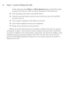
2. Select Cluster | New, as shown in Figure 6.50.
236 Chapter 6 • Implementing Windows Cluster Services and Network Load Balancing
Figure 6.50 Create a New NLB Cluster
301_BD_W2k3_06.qxd 5/13/04 3:06 PM Page 236
3. You will be presented with the Cluster Parameters window. Enter the IP address, Subnet
mask, and Full Internet name (this is the fully qualified domain name) of the cluster in the
Cluster IP configuration section, as shown in Figure 6.51.
4. Click the Multicast option in the Cluster operation mode section, and notice how the
Network address entry changes, as shown in Figure 6.52.The network (media access con-
trol, or MAC) changes to fit the correct mode based on the communication mechanism
you select. (We will leave Multicast selected for the example.)
5. Select the check box next to IGMP multicast, as shown in Figure 6.53.
Implementing Windows Cluster Services and Network Load Balancing • Chapter 6 237
Figure 6.51 Configure Cluster Parameters
Figure 6.52 Select Multicast Cluster Operation Mode
301_BD_W2k3_06.qxd 5/13/04 3:06 PM Page 237
6. You will be presented with the warning message shown in Figure 6.54.This message is
intended to remind you that additional configuration of your switches and NIC may be
required if you select IGMP support. Click OK to close the Warning dialog box.
7. You will be presented with the Cluster IP Addresses window, as shown in Figure 6.55. If
you want to load-balance multiple IP addresses, you can click the Add… button and add
them to the cluster at this point. For this example, we will work with only one address.
Click Next to continue.
238 Chapter 6 • Implementing Windows Cluster Services and Network Load Balancing
Figure 6.53 Select IGMP Multicast with the Cluster Operation Mode
Figure 6.54 IGMP Warning Message
Figure 6.55 Cluster IP Addresses Window
301_BD_W2k3_06.qxd 5/13/04 3:06 PM Page 238
8. In the Port Rules window, you see the default port rule, as shown in Figure 6.56.This rule
evenly distributes arriving traffic among all cluster hosts. Select the default port rule and
click Edit….
9. The Add/Edit Port Rule dialog box appears, as shown in Figure 6.57. As you can see, the
default port rule applies to all cluster IP addresses on all ports and protocols. It also directs
all client requests to the same cluster host (Multiple host/Single Affinity). Click Cancel to
avoid modifying the default port rule.
10. Click Next in the Port Rules window to advance to the Connect window.
11. Enter the name of a host in the Host field and click the Connect button. When the host
is identified, select the network interface to load-balance, as shown in Figure 6.58.Then
click Next.
Implementing Windows Cluster Services and Network Load Balancing • Chapter 6 239
Figure 6.56 The Port Rules Window
Figure 6.57 The Add/Edit Port Rule Dialog Box
301_BD_W2k3_06.qxd 5/13/04 3:06 PM Page 239
At this point, you may receive the warning message, as shown in Figure 6.59. If you receive this
message, you are using DHCP to assign an IP address to your network interface.You must use static
IP addresses on your network interfaces when using NLB.You must cancel the configuration,
change from DHCP to static IP addresses, and begin this process again.
12. You are now presented with the Host Parameters window, as shown in Figure 6.60. Enter
the Priority, Dedicated IP address, and Subnet mask for the cluster host. Set the Default
state of the host to Started. (This setting will make the host automatically attempt to join
the NLB cluster on startup). Click Finish.
240 Chapter 6 • Implementing Windows Cluster Services and Network Load Balancing
Figure 6.58 Connect to an NLB Node
Figure 6.59 DHCP Warning Message
Figure 6.60 Configure Host Parameters
301_BD_W2k3_06.qxd 5/13/04 3:06 PM Page 240
13. You are now taken back to the main window of the NLB Manager utility, which will look
similar to Figure 6.61.
14. The bottom pane of the window is the log of activities performed by the NLB Manager.
Double-click an entry. Figure 6.62 shows an example of the details that appear when Log
Entry 0004 was double-clicked. When you are finished viewing the log entry’s details,
click OK.
15. Click the NLB cluster you just created.You will see current details about your cluster, sim-
ilar to those shown in Figure 6.63.
Implementing Windows Cluster Services and Network Load Balancing • Chapter 6 241
Figure 6.61 The Configured NLB Cluster
Figure 6.62 View NLB Manager Log Entry Details
301_BD_W2k3_06.qxd 5/13/04 3:07 PM Page 241
16. Click the host you just configured.You will see the port rules, as shown in Figure 6.64.
242 Chapter 6 • Implementing Windows Cluster Services and Network Load Balancing
Figure 6.63 Configured NLB Cluster Details
Figure 6.64 Configured Port Rules on Cluster Node
301_BD_W2k3_06.qxd 5/13/04 3:07 PM Page 242
Planning, Implementing,
and Maintaining a High-
Availability Strategy
In this chapter:
■
Understanding Performance Bottlenecks
■
Planning a Backup and Recovery Strategy
■
Planning System Recovery with ASR
■
Planning for Fault Tolerance
Introduction
High availability is a buzzword in today’s networking world, and for good reason.
Ensuring that the network’s resources are available to users when they need them is an
important part of the network administrator’s job. Downtime—whether caused by a
disk failure, a performance slowdown, data loss due to an attack, or the loss of an entire
server due to a natural disaster such as fire or flood—cuts into worker productivity and
impacts the business’s bottom line or the organization’s ability to accomplish its goals.
In the previous chapter, we looked at server clustering and network load balancing
as part of a high-availability network. In this chapter, we will look at the concept of
high availability and how it can be attained. We’ll provide an overview of performance
bottlenecks and what causes them, and show you how to identify such common system
bottlenecks as memory, processor, disk, and network components. We’ll walk you
through the steps of using the System Monitor utility to track server performance and
show you how to use Event Viewer and service logs to monitor server issues, as well.
Next, we show you how to plan a backup and recovery strategy. We’ll review the
Windows Backup Utility and the differences between full, incremental, and differential
backups. We’ll also discuss the use of the Volume Shadow Copy feature as a backup
option. We’ll review how to decide what information should be backed up. We’ll also
show you how to back up user data, system state data, the Dynamic Host Configuration
Chapter 7
243
301_BD_w2k3_07.qxd 5/11/04 5:01 PM Page 243
Protocol (DHCP) database, Windows Internet Name Service (WINS) database, Domain Name
System (DNS) database, cluster disk signatures, and partition layouts. We’ll walk you through the
process of using the Windows Backup administrative tool, including the Backup and Restore
Wizard feature and the Advanced Mode feature. We’ll also discuss the use of command-line tools.
Then we’ll talk about how to select your backup media, and you’ll learn about scheduling backups
and how to restore data from backup when necessary.
We’ll address how to plan for system recovery using the Automated System Recovery (ASR)
feature.You’ll learn about system services, how to make an ASR backup, and how to do an ASR
restore. We’ll explain how ASR works and discuss alternatives to ASR such as the Safe Mode and
Last Known Good boot options. Finally, we’ll discuss the importance of planning for fault tolerance,
including solutions aimed at providing fault tolerance for local network connectivity, Internet con-
nectivity, data on disk, and mission-critical servers.
Understanding Performance Bottlenecks
All system administrators want the systems they install to run perfectly out of the box, all the time.
We have all wanted to be able to safely turn off our pagers and cell phones. Our servers should run
reliably, quickly, and without interruption, right? Well, if that were the case, we would all be termi-
nally bored or changing careers.
Identifying System Bottlenecks
For the most part, a Windows Server 2003 system does run well in its default configuration, and, if
designed and maintained properly, operates with a minimum of administrative overhead. However, as a
general-purpose operating system, it can often be tuned to perform better when used for certain tasks.
The main hardware resources of any computer system are used by different applications and cir-
cumstances in different combinations, often taxing one resource more than another. If multiple
applications are run on a system, it is often possible to reach the limit of a resource and suffer slow
response time, unreliable services, or missed transactions. We will take a look at each of these
resources, discuss some of the common issues related to them, and consider some of the manage-
ment options available.
Memory
RAM is most often the single resource that becomes a bottleneck. A common cause of slow perfor-
mance is insufficient physical memory.The minimum recommended amount of memory for run-
ning Windows Server 2003 is 128MB (512MB for Datacenter Edition).These are very conservative
numbers. Even Microsoft recommends at least 256MB. If you have the ability, double (or more)
these amounts, and you will be happy you did.The short rule with memory is this: more is better.
The Windows operating system controls the access to and allocation of memory and performs
“housekeeping tasks” when needed. Applications request memory from the operating system, which
allocates memory to the application. When an application no longer needs memory, the application
is supposed to release the memory back to the operating system. An application that does not prop-
erly release memory can slowly drain a system of available free memory, and overall performance
will suffer.This is referred to as a memory leak.
244 Chapter 7 • Planning, Implementing, and Maintaining a High-Availability Strategy
301_BD_w2k3_07.qxd 5/11/04 5:01 PM Page 244
Another performance factor related to memory is the use of virtual memory (VM) or paging.
Virtual memory is a method of increasing the amount of memory in a system by using a page file on
the hard drive.Access to hard drives, even on the fastest disk subsystems, is dozens or hundreds of
times slower than access to RAM. When the operating system needs more RAM than is available, it
copies the least recently used pages of memory to the page file, and then reassigns those pages of
RAM to the application that requested it.The next time a memory request occurs, the operating
system may need to reallocate more pages in RAM or retrieve pages from the page file.This paging
process can slow even the fastest system.
Tuning memory is often as simple as adding more memory, reducing the number of applications
running (including applications that run in the System Tray), or stopping unnecessary services.
However, there is an advanced memory-tuning technique that can be applied if the application sup-
ports it. Part of the Enterprise Memory Architecture feature of the Enterprise and Datacenter edi-
tions of Windows Server 2003 is 4GB tuning (4GT), also called application memory tuning. Using this
feature, you can change the amount of RAM addressable by applications from 2GB to 3GB.Your
system must have at least 2GB of physical RAM installed, and the application must be written to
support the increased memory range. Consult the application documentation or contact your
vendor to make this determination.
Processor
CPUs are commonly described by their type, brand, or model (for example, Pentium 4), and their clock
speed (for example, 2.0 GHz). In simplest terms, the clock speed is how many times per second the
CPU executes an instruction. Generally, the faster the CPU is, the better the computer performs.
The CPU bus architecture is another factor when examining performance. A 32-bit CPU (which
includes all of Intel’s CPUs from the 80386 through the Pentium 4 and AMD’s CPUs from the
Am486 through the Athlon-XP) can use integers 32 bits wide and access 2
32
bytes of memory, or
4GB. A 64-bit CPU (Intel’s Itanium series and AMD’s Opteron series) can use integers 64 bits wide
and access (in theory) 2
64
bytes of memory or 16 exabytes (16 billion gigabytes). No current hard-
ware can support this amount of RAM. Windows Server 2003 supports a maximum of 512GB on
Itanium-based hardware with the Datacenter Edition.The point is that 64-bit CPUs can support
significantly more memory and run applications that use more of it than 32-bit CPUs, all at a faster
speed. Extremely large databases can get a large performance boost on 64-bit systems.
Using multiple CPUs in a computer (called multiprocessing) allows a computer system to run
more applications at the same time than a single-CPU system, because the workload can be spread
among the processors. In effect, this reduces the competition among applications for CPU time.A
related programming technology called multithreading allows the operating system to run different
parts of an application (threads) on multiple CPUs at the same time, spreading out the workload.
Windows Server 2003 can support up to 64 CPUs, depending on the edition of the operating
system in use.
A recent development by Intel is a technology called hyperthreading.This feature, introduced in
the Xeon and Pentium 4 series of processors, makes a single CPU appear to be two CPUs.
Hyperthreading is implemented at the BIOS level and is therefore transparent to the operating
system. It typically yields a performance increase of 20 to 30 percent, meaning it is not as efficient as
multiple physical CPUs. However, it is included free on hardware that supports the technology.
Planning, Implementing, and Maintaining a High-Availability Strategy • Chapter 7 245
301_BD_w2k3_07.qxd 5/11/04 5:01 PM Page 245