Microsoft SQL Server 2008 R2 Unleashed- P73 ppsx
Bạn đang xem bản rút gọn của tài liệu. Xem và tải ngay bản đầy đủ của tài liệu tại đây (867.57 KB, 10 trang )
ptg
664
CHAPTER 21 SQL Server Clustering
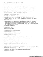
FIGURE 21.5 An Excel spreadsheet for a two-node active/passive SQL Cluster configuration.
The cluster controls the following resources:
. Physical disks (Q: is for the quorum disk, S: is for the shared disks, and so on.)
. The cluster IP address
. The cluster name (network name)
. The Distributed Transaction Coordinator (MSDTC)
. The SQL Server virtual IP address
. The SQL Server virtual name (network name)
. SQL Server
. SQL Server Agent
. The SQL Server Full-Text Search service instance (if installed)
After you successfully install, configure, and test your cluster (MSCS), you are ready to add
the SQL Server components as resources to be managed by MSCS. This is where the magic
Download from www.wowebook.com
ptg
665
Installing SQL Server Clustering
21
happens. Figure 21.6 shows how the Cluster Administrator should look after you
install/configure MSCS. It doesn’t have SQL Server 2008 installed yet.
Installing SQL Server Clustering
When you install SQL Server in a clustered server configuration, you create it as a virtual
SQL Server. A virtual SQL Server is not tied to a specific physical server; it is associated with
a virtualized SQL Server name that is assigned a separate IP address (not the IP address or
name of the physical servers on which it runs). Handling matters this way allows for your
applications to be completely abstracted away from the physical server level.
Failover clustering has a new workflow for all Setup scenarios in SQL Server 2008. The two
options for installation are
. Integrated installation—This option creates and configures a single-node SQL
Server failover cluster instance. Additional nodes are added by using the Add Node
functionality in Setup. For example, for Integrated installation, you run Setup to
create a single-node failover cluster. Then you run Setup again for each node you
want to add to the cluster.
. Advanced/Enterprise installation—This option consists of two steps; the prepare
step prepares all nodes of the failover cluster to be operational. Nodes are defined
and prepared during this initial step. After you prepare the nodes, the Complete step
is run on the active node—the node that owns the shared disk—to complete the
failover cluster instance and make it operational.
Figure 21.7 shows the same two-node cluster configuration as Figure 21.1, with all the SQL
Server components identified. This virtual SQL Server is the only thing the end user will
ever see. As you can also see in Figure 21.7, the virtual server name is
VSQLSERVER2008,
and the SQL Server instance name defaults to blank (you can, of course, give your
instance a name). Figure 21.7 also shows the other cluster group resources that will be part
of the SQL Server Clustering configuration: MSDTC, SQL Agent, SQL Server Full-Text
Search, and the shared disk where the databases will live.
FIGURE 21.6 Windows 2003 Cluster Administrator, showing managed resources prior to
installing SQL Server.
Download from www.wowebook.com
ptg
666
CHAPTER 21 SQL Server Clustering
SQL
Connections
SQL Clustering basic configuration
CLUSTER 1
CLUSTER GROUP
Resources
CLUSTER 2
Windows 2003 EE
SQL Server 2008 (physical)
Windows 2003 EE
MS DTC
SQL Agent
SQL Full Text
Search
Q:
Quorum
Disk
SQL Server 2008 (physical)
SQL Server 2008
(Virtual SQL Server)
ClusterPublic
ClusterInternal
Local
Binaries
Local
Binaries
C:
C:
Master DB
TempDB
Appl 1 DB
VSQLSERVER2008
SSShhhaaarrreeeddd
Shared
FIGURE 21.7 A basic SQL Server Clustering configuration.
SQL Server Agent will be installed as part of the SQL Server installation process, and it is
associated with the SQL Server instance it is installed for. The same is true for SQL Server
Full-Text Search; it is associated with the particular SQL Server instance that it is installed
to work with. The SQL Server installation process completely installs all software on all
nodes you designate.
Configuring SQL Server Database Disks
Before we go too much further, we need to talk about how you should lay out a SQL
Server implementation on the shared disks managed by the cluster. The overall usage
intent of a particular SQL Server instance dictates how you might choose to configure
your shared disk and how it might be best configured for scalability and availability.
In general, RAID 0 is great for storage that doesn’t need fault tolerance; RAID 1 or RAID 10
is great for storage that needs fault tolerance but doesn’t have to sacrifice too much perfor-
mance (as with most online transaction processing [OLTP] systems); and RAID 5 is great
for storage that needs fault tolerance but whose data doesn’t change that much (that is,
low data volatility, as in many decision support systems [DSSs]/read-only systems).
All this means that there is a time and place to use each of the different fault-tolerant disk
configurations. Table 21.1 provides a good rule of thumb to follow for deciding which
SQL Server database file types should be placed on which RAID level disk configuration.
(This would be true regardless of whether or not the RAID disk array was a part of a SQL
Server cluster.)
Download from www.wowebook.com
ptg
667
Installing SQL Server Clustering
21
TIP
A good practice is to balance database files across disk arrays (that is, controllers). In
other words, if you have two (or more) separate shared disk arrays (both RAID 10) avail-
able within a cluster group’s resources, you should put the data file of Database 1 on
the first cluster group disk resource (for example, DiskRAID10-A) and its transaction
log on the second cluster group disk resource (for example, DiskRaid10-B). Then you
should put the data file of Database 2 on the second cluster group disk resource of
DiskRAID10-B and its transaction log on the first cluster group disk resource of
DiskRAID10-A. In this way, you can stagger these allocations and in general balance
the overall RAID controller usage, minimizing any potential bottlenecks that might occur
on one disk controller. In addition, FILESTREAM filegroups must be put on a shared
disk, and FILESTREAM must be enabled on each node in the cluster that will host the
FILESTREAM instance. You can also use geographically dispersed cluster nodes, but
additional items such as network latency and shared disk support must be verified
before you get started. Check the Geographic Cluster hardware Compatibility List
( On Windows 2008, most
hardware and ISCSI supported hardware can be used, without the need to use “certi-
fied hardware.” When you are creating a cluster on Windows 2008, you can use the
cluster validation tool to validate the Windows cluster; it also blocks SQL Server Setup
when problems are detected with the Windows 2008 cluster.
TABLE 21.1 SQL Server Clustering Disk Fault-Tolerance Recommendations
Device Description Fault Tolerance
Quorum drive The quorum drive used with MSCS should
be isolated to a drive by itself (often
mirrored as well, for maximum availability).
RAID 1 or RAID 10
OLTP SQL Server database files For OLTP systems, the database
data/index files should be placed on a
RAID 10 disk system.
RAID 10
DSS SQL Server database files For DSSs that are primarily read-only, the
database data/index files should be
placed on a RAID 5 disk system.
RAID 5
tempdb This is a highly volatile form of disk I/O
(when not able to do all its work in the
cache).
RAID 10
SQL Server transaction log files The SQL Server transaction log files should
be on their own mirrored volume for both
performance and database protection. (For
DSSs, this could be RAID 5 also.)
RAID 10 or RAID 1
Download from www.wowebook.com
ptg
668
CHAPTER 21 SQL Server Clustering
Installing Network Interfaces
You might want to take a final glance at Cluster Administrator so that you can verify that
both CLUSTER1 and CLUSTER2 nodes and their private and public network interfaces are
completely specified and their state (status) is up. If you like, you should also double-
check the IP addresses and network names against the Excel spreadsheet created for this
cluster specification.
Installing MSCS
As you can see in Figure 21.8, the MSCS “service” is running and has been started by the
ClusterAdmin login account for the GOTHAM domain.
NOTE
If MSCS is not started and won’t start, you cannot install SQL Server Clustering. You have
to remove and then reinstall MSCS from scratch. You should browse the Event Viewer to
familiarize yourself with the types of warnings and errors that can appear with MSCS.
Installing SQL Server
For SQL Clustering, you must install a new SQL Server instance within a minimum two-
node cluster. You should not move a SQL Server instance from a nonclustered configura-
tion to a clustered configuration. If you already have SQL Server installed in a
nonclustered environment, you need to make all the necessary backups (or detach data-
bases) first, and then you need to uninstall the nonclustered SQL Server instance. Some
FIGURE 21.8 You n eed to make su re M SCS is r unning an d st ar ted by the cluster account for
the domain.
Download from www.wowebook.com
ptg
669
Installing SQL Server Clustering
21
upgrade paths and migration paths are possible from prior versions of SQL Server and
Windows server. You are also limited to a maximum of 25 instances of SQL Server per
failover cluster. There is no uninstall SQL Server failover cluster option; you must run
Setup from the node that is to be removed. You must specify the same product key on all
the nodes that you are preparing for the same failover cluster. You also should make sure
you use the same SQL Server instance ID for all the nodes that are prepared for the
failover cluster.
With all MSCS resources running and in the online state, you run the SQL Server Setup
program from the node that is online (for example, CLUSTER1). You are asked to install all
software components required prior to installing SQL Server (.NET Framework 3.0 or 3.5,
Microsoft SQL Native Client, and the Microsoft SQL Server 2008 Setup support files).
SQL Server integrated failover cluster installation consists of the following steps:
1. Create and configure a single-node SQL Server failover cluster instance. When you
configure the node successfully, you have a fully functional failover cluster instance.
At this point, it does not have high availability because there is only one node in the
failover cluster.
2. On each node to be added to the SQL Server failover cluster, run Setup with Add
Node functionality to add that node.
Alternatively, you can use the following SQL Server Advanced/Enterprise failover cluster
installation:
1. On each node that will be an owner of the new SQL Server failover cluster, follow
the Prepare Failover Cluster setup steps listed in the Prepare section. After you run
the Prepare Failover Cluster on one node, Setup creates the Configuration.ini file,
which lists all the settings you specified. On the additional nodes to be prepared,
instead of following these steps, you can supply the Configuration.ini file from
first node as an input to the Setup command line. This step prepares the nodes
ready to be clustered, but there is no operational instance of SQL Server at the end
of this step.
2. After the nodes are prepared for clustering, run Setup on one of the prepared nodes,
preferably on the node that owns the shared disk that has the Complete Failover
Cluster functionality. This step configures and finishes the failover cluster instance.
After completing this step, you have an operational SQL Server failover cluster
instance. and all the nodes prepared previously for that instance are the possible
owners of the newly created SQL Server failover cluster.
After you take these steps, the standard Welcome to SQL Server Installation Center Wizard
begins. It starts with a System Configuration check of the node in the cluster (CLUSTER1).
Figure 21.9 shows the SQL Server Installation Center launch dialog and the results of a
successful system check for CLUSTER1.
Download from www.wowebook.com
ptg
670
CHAPTER 21 SQL Server Clustering
NOTE
SQL Server Clustering is available with SQL Server 2008 Standard Edition, Enterprise
Edition, and Developer Edition. However, Standard Edition supports only a two-node
cluster. If you want to configure a cluster with more than two nodes, you need to
upgrade to SQL Server 2008 Enterprise Edition.
If this check fails (warnings are acceptable), you must resolve them before you continue. If
the check is successful, you are then prompted for the checklist of features you want to
install. Figure 21.10 shows the Feature Selection to install dialog.
You then see the Instance Configuration dialog, as shown in Figure 21.11, where you
specify the network name for the new SQL Server failover cluster (the Virtual Server name,
VSQLSERVER2008 in this example) and then either can use the default SQL Server instance
name (no name) or specify a unique SQL Server instance name (we chose to use the
default instance name of MSSQLSERVER).
This virtual SQL Server name is the name the client applications will see (and to which
they will connect). When an application attempts to connect to an instance of SQL Server
2008 that is running on a failover cluster, the application must specify both the virtual
server name and instance name (if an instance name was used), such as
VSQLSERVER2008\VSQLSRV1 (virtual server name\SQL Server instance name) or
VSQLSERVER2008 (just the virtual server name without the default SQL Server instance
FIGURE 21.9 A Microsoft SQL Server Setup Support Rules check.
Download from www.wowebook.com
ptg
671
Installing SQL Server Clustering
21
FIGURE 21.10 The SQL Server Setup Feature Selection dialog for a SQL Server Failover
Cluster.
FIGURE 21.11 Specifying the virtual server name (VSQLSERVER2008) and default instance.
Download from www.wowebook.com
ptg
672
CHAPTER 21 SQL Server Clustering
name). The virtual server name must be unique on the network. You also specify the local
directory locations (root) for the installation.
NOTE
A good naming convention to follow is to preface all virtual SQL Server names and vir-
tual SQL Server instance names with a V. This way, you can easily identify which SQL
Server machines on your network are clustered. For example, you could use
VSQLSERVER2008 as a virtual SQL Server name and VSQLSRV1 as an instance name.
Next comes the disk space requirements dialog, followed by the Cluster Resource Group
specification. This is where the SQL Server resources are placed within MSCS. Here, you
use the existing resource cluster group (named Cluster Group). Immediately following the
resource group assignment comes the identification of which clustered disks are to be used
via the Cluster Disk Selection dialog, shown in Figure 21.12. It contains an S: drive
(which you want SQL Server to use) and Q: and R: drive being used for the quorum files
(do not select this drive!). You simply select the available drive(s) where you want to put
your SQL database files (the S: drive in this example). As you can also see, the only “quali-
fied” disk is the S: drive. If the quorum resource is in the cluster group you have selected,
a warning message is issued, informing you of this fact. A general rule of thumb is to
isolate the quorum resource to a separate cluster group.
FIGURE 21.12 Cluster resource group specification and Cluster Disk Selection.
Download from www.wowebook.com
ptg
673
Installing SQL Server Clustering
21
The next thing you need to do for this new virtual server specification is to identify an IP
address and which network it should use. As you can see in the Cluster Network
Configuration dialog, shown in Figure 21.13, you simply type in the IP address (for
example, 192.168.3.110) that is to be the IP address for this virtual SQL Server for the
available networks known to this cluster configuration (in this example, it is for the
ClusterPublic network). If the IP address being specified is already in use, an error occurs.
NOTE
Keep in mind that you are using a separate IP address for the virtual SQL Server that
is completely different from the cluster IP addresses. In a nonclustered installation of
SQL Server, the server can be referenced using the machine’s IP address. In a clus-
tered configuration, you do not use the IP addresses of the servers themselves;
instead, you use this separately assigned IP address for the “virtual” SQL Server.
Figure 21.14 shows the next step in identifying the Cluster Security Policy for each SQL
Server component (Database Engine, SQL Server Agent, and Analysis Services). Here, you
use the domain Admin group. Figure 21.14 also shows the Server Configuration “service
accounts” to use for all the services within this SQL Server install. You use a ClusterAdmin
account set up for this purpose. Remember, this account must have administrator rights
within the domain and on each server (that is, it must be a member of the Administrators
local group on any node in the cluster). This is followed by the Database Engine
Configuration dialog, where you set what type of authentication mode to use, the data
FIGURE 21.13 Specifying the virtual SQL Server IP address and which network to use.
Download from www.wowebook.com