Chapter 2: Batteries for Electrically Powered Industrial Trucks potx
Bạn đang xem bản rút gọn của tài liệu. Xem và tải ngay bản đầy đủ của tài liệu tại đây (392.63 KB, 18 trang )
2
Batteries for Electrically Powered
Industrial Trucks
H. A. KIEHNE
2.1 INTRODUCTION
Electrically powered road vehicles are currently more and more debated and many
new prototypes of vehicles and batteries have been presented, e.g. at the 18th
International Battery, Hybrid and Fuel Cell Electric Vehicle Symposium and
Exhibition in October 2001 in Berlin, Germany, the world’s largest event on this
topic under the motto ‘‘Clean and efficient mobility for the millennium’’. While for
materials handling battery-powered trucks, elevating trucks, forklifts, and other
vehicles for internal factory transportation have been used for decades, today the
market for electric road vehicles seems to be open only in some niches, because of the
relative higher initial costs. As environmental laws tighten and oil and gasoline
become more expensive, battery-powered machinery gains importance in more than
one regard. Table 2.1 gives a view of the variety of battery electric powered vehicles.
For more on electric road vehicles see Chapter 4.
2.2 DEMANDS OF THE MARKET
The demands concerning batteries can be listed in short as follows:
. Easy service, long service intervals, mainten ance freedom, highest possible
performance at unchanged weight and size. All of the above are expected in
connection with optimized service life.
Copyright © 2003 by Expert Verlag. All Rights Reserved.
. The vehicles must be of rugged design; the same goes for the batteries
powering them; they should be indifferent to exhaustive discharge and low
temperatures. On top of all that there is the demand for economy in
comparison with other energy sources or powering systems.
This package of demands is presently almost fulfilled.
Sophisticated battery systems do already exist, such as the battery of a MAN-
bus, which continuously checks its state by a number of well-tested peripheral
devices, such as a centralized water refilling system, a centralized gas disposal, a
temperature-controlling device, and a discharge/charge surveying apparatus.
In the German city of Du
¨
sseldorf buses powered by such batteries have covered
in 16-hours-per-day regular service more than 140,000 km per battery before the end
of service life.
Battery systems are presently available for industrial trucks, easily recharged
by new-generation control circuits that also permanently survey the batteries’ state
of charge.
All these batteries are of tubular cell design, commonly employed in industrial
trucks throughout Europe. Three reasons for this are: their overwhelming life
expectancy, which has been practically determined to be greater than 5 years; their
Table 2.1 Battery powered vehicles.
Traffic range
Type of vehicle
Rooms in
buildings Outdoor
Roads and
streets Rails Water Air
Land operating vehicles
Materials handling trucks (.)
– Forklift trucks (.)
– Pedestrian and pallet
trucks
– Tow tractors (.)
– AGVs . (.)
Special operating
machines
.
– Cleaning machines .
Rail vehicles .
– Locomotives .
– Mining locomotives .
– Railway coaches .
Electric road vehicles
– Bicycles, motorcycles
– Wheelchairs .
– Passenger cars .
– Vans
– Lorries, trucks
– Motor coaches, buses (.) .
Ships .
Aircrafts .
Copyright © 2003 by Expert Verlag. All Rights Reserved.
low weight/power ratio and high power density; and last but not least their favorable
lifetime/costs ratio and the experienced economy. Only smaller, especially hand-
directed vehicles are preferably fitted with monobloc batteries or grid-type plate cells.
Apart from the standardized battery sizes there are innumerable battery
designs due to the variety of industrial trucks being in action, that differ only in small
details such as lifting eyelets, terminals, and locking catches for fixing in the truck.
Not only experts, but also the users of the manifold types of battery vehicles
know that this is a simpler system compared to vehicles powered by internal
combustion engines. This means battery/electric materials handling is highly
economic and avoids pollution in the surroundings where exhausted gasses and
noise cannot be tolerated, e.g. in warehouses, food markets, an d factories where
workers want a healthy atmosphere.
2.3 STANDARDIZED DESIGNS
As it is important for the applicant to know the present situation of the standards, a
survey of the presently standardized cells and batteries shall be given.
DIN (Deutsche Industrie Normen) and VDE standards (Verein Deutscher
Elektriker) are valid only inside national borders; more and more they are
substituted by European Norm (EN) Standards and international standards, the
IEC Standards (International Electrotechnical Commission) and ISO standards
(International Standardization Organization), as for instance for battery voltages.
Generally all batteries must be designed and manufactured in accordance with the
VDE directions (VDE 0501/.1.77). See, for example, Table 2.2.
These directions for instance cover the classification and the consistency of the
electrolyte and of refill water and how batteries must be fitted in containers for safety
reasons (VDE 0510 is at present time under revision). See also Chapter 6 and 14.
Concerning the single-cell designs of tubular plate cells two standards sheets
inform of nominal capacities and main dimensions:
1. DIN 43 595: Tubular plate cells for land- and water-bound vehicles, low
maintenance type.
2. DIN 43 567 part 2: Tubular plate cells for land- and water-bound vehicles.
DIN 43 595 concerns cells of the low maintenance type with compound sealed
or welded cell lids. The connector bars are permanently attached to the terminals by
means of welding or crimping on. The main dimensions only vary slightly from the
earlier DIN 43 567. DIN 43 595 recently has been drawn back, while the dimens ions
are still valid and conform to the international standard IEC 60 254-2. New types
with higher capacities will be listed in a new standard, having the same dimensions
(see Table 2.3).
DIN 43 567 concerns tubular plate cells with bolted connectors, with flat
terminals and with conical terminals for the ex types up to VDE 0170/0171 for
explosion-safe types. The lids of these types can be removed and are sealed by a
flexible rubber seal.
The overall dimensions of these tubular plate-type cells also accord to the IEC
Standard 60 254-2, ‘‘Lead-acid traction batteries, part 2, cell dimensions for traction
batteries’’.
Copyright © 2003 by Expert Verlag. All Rights Reserved.
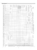
Table 2.2 Survey of the PzS standard cells to DIN 43 595.
Cell height (mm) Cell width (mm)
Nominal capacity K
5
(Ah) with varying number of positive plates
Plate size (max.) (max.) 2 3 45678910
PzS 55 365 110 165 220 275 330 385 440 — —
PzS 70 425 140 210 280 350 420 490 560 — —
PzS 80 505 198 160 240 320 400 480 560 640 — 800
PzS 100 595 200 300 400 500 600 720 800 900 1000
PzS 120 752 — 360 480 600 720 840 960 — 1200
length of cells (mm) 47 65 83 101 119 137 155 174 192
a
Including terminal end with mounted intercell connectors.
Copyright © 2003 by Expert Verlag. All Rights Reserved.
DIN 43 595 is preferred more and more as it has the following advantages:
. High operational safety through complete insulation.
. Improved cyclic durability through optimized masses and plate geometry.
. Great number of cycles through lowering of the mud fallout rate.
. Substantially higher maintenance intervals through electrolyte-t ight cells.
Cells of these types undergo not only severe testing in practical applications, but also
tests to the DIN 43 539 part 3, as well as the lEC tests of the same content and extent
in laboratories for quality improvement, with endurance tests demanding over 1500
cycles in cyclic charging/discharging operation (see IEC 60 254-1).
Each standard needs an update following the technical development. So when
the new international standard for dimensions of traction lead-acid cells IEC 60 254-
2 was published and harmonized in the European Union to a European standard EN
60 254-1, DIN 43 595 was drawn back. In an additional technical information sheet,
published by the German Battery Manufacturers Association, the (nominal)
capacities in use were listed in relation to the cell dimensions. Table 2.3 shows the
range of cell heights conforming to IEC (respective EN 60 254-2) together with the
new series of higher capacities.
Compared with cells of the older design the ‘‘high-capacity cells’’ have an
increased capacity between 9 to 17%. Table 2.4 shows the data for the new series of
PzS cells.
Standards sheets also have existed apart from the above mentioned for battery
trays for several years. In certain intervals standards sheets must be revised to
consider new developments.
In the past, standardization of parts making up a battery such as cells,
connectors, trays, parts of installation and terminals was ascribed a great advantage
by the users’ side because of the great number of combinations possible to assemble a
battery. Modification and repair of batteries was common then.
The main disadvantage of the single parts standards is that this leads to a huge
amount of types and variants, as changed details can be accepted for new batteries,
but by no means from the spare parts side.
Designers and manufacturers of industrial trucks and battery manufacturers
have developed a standard of the 24-V and the 80-V standard batteries to take over
Table 2.3 Survey on capacities of plates type PzS (normal) and PzS-H (high capacity).
Cell height (max)
Capacity C/PzS plate
[Ah]
Capacity increase
[mm] series L (new) PzS. . .L DIN (old) PzS %
370 60 55 9
440 80 70 14
510 90 80 13
605 110 100 10
750 140 120 17
Copyright © 2003 by Expert Verlag. All Rights Reserved.
Table 2.4 Lead-acid traction cells with tubular plates, series L, dimensions conforming to
IEC 60 254-2.
Nominal
Dimensions
d
Weight
including Lead
capacity Code
b
a (h) electrolyte content
c
C
5
a
tubular 0 (kg) (kg)
Designation code (Ah) plate À2 (max.) (+ 5%)(+ 5%)
2 PzS 120 L 120
PzS 60
47 8.4 6.2
3 PzS 180 L 180 65 11.8 8.8
4 PzS 240 L 240 83 15.5 11.5
5 PzS 300 L 300 101 370 19.0 14.1
6 PzS 360 L 360 119 22.5 16.8
7 PzS 420 L 420 137 26.1 19.4
8 PzS 480 L 480 155 29.8 22.2
2 PzS 160 L 160
PzS 80
47 9.8 7.3
3 PzS 240 L 240 65 14.0 10.4
4 PzS 320 L 320 83 18.1 13.5
5 PzS 400 L 400 101 440 22.6 16.8
6 PzS 480 L 480 119 26.6 19.8
7 PzS 560 L 560 137 31.1 23.1
8 PzS 640 L 640 155 35.2 26.3
2 PzS 180 L 180
PzS 90
47 12.0 9.0
3 PzS 270 L 270 65 16.9 12.6
4 PzS 360 L 360 83 21.6 16.1
5 PzS 450 L 450 101 510 26.3 19.5
6 PzS 540 L 540 119 31.1 23.1
7 PzS 630 L 630 137 36.1 26.9
8 PzS 720 L 720 155 40.8 30.3
10 PzS 900 L 900 192 50.3 37.4
2 PzS 220 L 220
PzS 110
47 14.3 10.6
3 PzS 330 L 330 65 20.3 15.1
4 PzS 440 L 440 83 26.0 19.4
5 PzS 550 L 550 101 31.8 23.6
6 PzS 660 L 660 119 605 37.9 28.2
7 PzS 770 L 770 137 43.8 32.6
8 PzS 880 L 880 155 49.8 37.0
9 PzS 990 L 990 174 55.7 41.5
10 PzS 1100 L 1100 192 61.5 45.7
3 PzS 420 L 420
PzS 140
65 25.4 18.9
4 PzS 560 L 560 83 32.9 24.5
5 PzS 700 L 700 101 39.9 29.7
6 PzS 840 L 840 119 750 47.2 35.2
7 PzS 980 L 980 137 54.8 40.8
8 PzS 1120 L 1120 155 62.3 46.3
10 PzS 1400 L 1400 192 76.7 57.1
a
C
5
¼ 5 h rated capacity ¼ nominal capacity (see IEC 60 254–1).
b
Code of a plate with a capacity of, e.g. 60 Ah: PzS 60.
c
Loss during production of 7% included.
d
Width 198 mm À2.
Copyright © 2003 by Expert Verlag. All Rights Reserved.
the older ‘‘component standards’’ (see Figures 2.1 and 2.2). The sheets in question
are
. DIN 43 535 Lead-acid accumulators; traction batteries 24 V for industrial
trucks.
Figure 2.1 Circuits of 24-V traction batteries to DIN 43 535.
Figure 2.2 Circuits of 80-V traction batteries to DIN 43 536.
Copyright © 2003 by Expert Verlag. All Rights Reserved.
. DIN 43 536 Lead-acid accumulators; traction batteries 80 V for industrial
trucks.
DIN 43 535 mentions three main circuits of type A, B, C:
. 19 batteries of the A circuit type.
. 15 batteries of the B circuit type.
. 12 batteries of the C circuit type.
that have been standardized, in all 46 batteries of 24 V.
DIN 43 536 mentions two main circuits of the types A and B:
. 18 batteries of type A.
. 6 batteries of type B.
that have been standardized, in all 24 battery types of 80 V.
In other countries 48-V and 72-V batteries are more popular and standardized.
So it was necessary to complete the line of battery standards with DIN 43 531 for the
48-V traction batteries to conform to the two other above-mentioned standards for
24 and 80 V.
These standard batteries (see Figure 2.3) have the following in common:
. The battery trays are all of the same design.
. Length, width, and height are standardized.
. The design and location of the lifting eyes are standardized.
. The connecting terminals are described in a special informal sheet published
by the German Battery Manufacturers Association.
Figure 2.3 Design of a modern traction battery.
Copyright © 2003 by Expert Verlag. All Rights Reserved.
. Insulation of the tray (mostly a plastic coating) accords to VDE 0510-
standards.
. Battery trays are always fitted with the greatest possible cell capacity.
. No ballast weights are employed.
Figure 2.3 shows the design of a modern 24-V traction batte ry with positive
tubular plates to DIN 43 535.
With this step toward a reasonable standardization of batteries two
substantially important aspects for future developments have come into close range:
. Following a certain transitional period a noticeable reduction of variants
and types of cells and trays.
. Introduction of new technologies in battery design resulting in less
maintenance.
Standard voltages for traction batteries for industrial trucks are fixed by the ISO
1044 standards as follows:
. Series I: 12, 24, 36, 48, 60, 72, and 96 V.
. Series II: 40 and 80 V.
In Germany only 24 V and 80 V are common values.
The above-mentioned traction batteries in grid plate design for smaller vehicles
are treated by DIN 43 594. A revised standard will be edited for monobloc batteries
in plastic containers (containers as in use for automotive batteries). The pasted plates
are thicker; the batteries have a special separation between the plates (see Table 2.5).
A parallel new standard, DIN 43 598, is in preparation: Part 1 for small
traction batteries with positive tubular plates in monoblocs corresponding to DIN 43
594. Part 2 for small traction cells in plastic trays. (See Tables 2.6 and 2.7.)
2.4 ENERGY/WEIGHT AND ENERGY/VOLUME RATIOS
The display of standardized values may create the impression of a power level being
cemented or fixed. The applicant of lead-acid traction batteries today may not realize
the improvements that have made concerning energy/weight and energy/ volume
ratios.
Forerunners of these more powerful batteries of the tubular plate type and also
of the grid plate type have been tested in electric road vehicles. Naturally the classic
lead-acid battery has a limit which lies far below the theoretical value of 161 Wh/kg.
By showing the shares of weight of conductive material, excess mass, and excess
electrolyte and inactive material, Figure 2.4 explains why the possibilities for
improvement of the energy/weight ratio are so few.
The values for the energy/weight and the energy/volume ratios (like the above
values) are related to a 5-hour discharge.
Figure 2.5 displays the specific drawable energy pe r kg dependent on the
currents drawn in a much-simplified manner. At a load of the 5-hour discharge
current, the PzS cells yield about 30 Wh/kg. Only about 50% of this value is available
if the cell is drained with the 1-hour discharge current value. This amounts to only
10% of the theoretical value of 161 Wh/kg. This entitles the developer and the user to
expect severe improvements, at least on the high-drain sector.
Copyright © 2003 by Expert Verlag. All Rights Reserved.
Figure 2.4 Theoretical and practical energy/weight ratio of lead-acid cells.
Figure 2.5 Comparison of specific energy yield of PzS cells.
Copyright © 2003 by Expert Verlag. All Rights Reserved.
Table 2.5 Lead-acid traction batteries, monobloc battery with pasted plates (DIN 43594).
Nominal Nominal
Dimensions
Battery marking
Voltage capacity
a
Monobloc a b h
Short designation Type no. (V) (Ah) type (max) (max) (max)
6 V GiS 180 9 180.1 6 180 M 13 244 190 275 30
12 V GiS 40 9 540.1 12 40 H 4 211 175 190 14
12 V GiS 50 9 550.1 12 50 H 5 246 175 190 16
12 V GiS 60 9 560.1 12 60 H 6 306 175 190 20
12 V GiS 75 9 575.1 12 75 H 8 381 175 190 24
12 V GiS 105 9 605.1 12 105 M 20 513 189 223 40
12 V GiS 135 9 635.1 12 135 M 25 513 223 223 48
12 V GiS 180 9 680.1 12 180 M 33 518 291 242 64
a
Nominal capacity after 10 discharges; electrolyte density 1.28 + 0.01 kg/L; electrolyte temperature 25 8C.
Copyright © 2003 by Expert Verlag. All Rights Reserved.
Table 2.6 Lead-acid traction batteries, monobloc batteries with positive tubular plates (DIN 43 598 part 1).
Nominal
voltage
(V)
Nominal
capacity
a
(Ah)
Monobloc type
Dimensions
Total weight
(kg + 5%)
Short designation
a
(max)
b
(max)
h
(max)
6 V PzS 170 6 170 M 13 244 190 275 30
12 V PzS 75 12 75 M 20 513 189 223 34
12 V PzS 100 12 100 M 20 513 189 223 40
12 V PzS 130 12 130 M 25 513 223 223 48
12 V PzS 150 12 150 M 33 518 291 242 61
12 V PzS 170 12 170 M 33 518 291 242 64
a
Nominal capacity after 10 discharges electrolyte density 1.28 + 0.01 kg/L; electrolyte temperature 25 8C.
Table 2.7 Lead-acid traction batteries in plastic trays with single cells and positive tubular plates (DIN 43 598 part 2).
Short designation
Nominal
capacity C
5
a
(Ah) Circuit
Dimensions
Total weight
filled
(kg + 5%)
a
1
(max)
a
2
(max)
b
1
(max)
b
2
(max)
h
(max)
6 V PzS 104 H 104 A 248 253 168 168 235 22.7
6 V PzS 130 H 130 A 303 318 168 168 235 27.8
6 V PzS 172 H 172 A 245 251 194 194 280 34.2
12 V PzS 104 H 104 B 486 506 168 168 223 45.1
12 V PzS 130 H 130 B 486 506 205 205 223 55.3
12 V PzS 172 H 172 C 486 506 199 199 279 68.4
a
Nominal capacity after 10 discharges; electrolyte density 1.28 + 0.01kg/L; electrolyte temperature 25 8C.
Copyright © 2003 by Expert Verlag. All Rights Reserved.
Figure 2.6 shows the specific drawable energy of lead-acid traction batteries of
different designs. The lower graph represents the capacity of the common PzS cells.
Further development of this cell type for application in electric road vehicles of the
PzF type yiel ds accordingly higher values.
2.5 SERVICE LIFE AND ECONOMY
The service life of traction batteries, depending on the average load during
operation, is located somewhere between 3 to 9 years. The average lifespan thus is
5.5 to 6 years, corresponding 1500 to 1600 discharges to 80% of the nominal
capacity. It is understandable that no ‘‘standard’’ service life value can be given
independent of the load profile. The following can influence lifetime and economy:
. Choice of a too small battery resulting in frequent or even permanent
exhaustive discharges.
. Severe on-duty conditions and resulting permanent temperatures over
50 8C.
. Permanent overcharging because of faulty charging technique or malad-
justed charging devices.
. Storage of uncharged batteries.
Especially the choice of too small battery capacity generally leads to bad results in
service life. For further details see information sheet published by the German
Battery Manufacturers Association.
Figure 2.6 Useable fraction of the energy/weight ratio in Wh/kg of lead-acid PzS cells, PzF
cells, and GF cells (GF ¼ flat plate type).
Copyright © 2003 by Expert Verlag. All Rights Reserved.
2.6 CHARGING TECHNIQUES
Demands on charging techniques and monitoring systems include:
. Choice of a preserving charge method.
. Controlling of the charge process regarding the condition of the battery
(electronic diary).
. Indication of the actual capacity.
. Current limitations.
. Deep discharge protection.
. Control of voltage and temperature of the battery and charging.
Charging devices should have a characteristic curve following DIN 41 773 and be
equipped with a charge-control switch that limits the charging period, as shown in
Figure 2.7 after gassing voltage of 2.4 V/cell has been reached.
The charging-control ‘‘Poehlertronic’’ switch actuates the additional charge
considering the batteries age and temperature and compensates the mains’
fluctuations optimally. This charging timer also prolongs the life span of a battery
and facilitates maintenance as there is less water consumption, and overcharging is
impossible even with older batteries (see Figure 2.8).
Apart from this, other principles for controlling the charging pro cess of a
battery are operational, such as the controlling of the charging process by measuring
the gas adsorption rate with recombinators (HOC charging device from Hoppecke)
and by monitoring the charging current (Belatron system from the Benning
Corporation).
Several devices, ranging from a simple voltage controller to a sophisticated
electronic apparatus minutely balancing the Ah household, can monitor state of
charge. A type of safety switch has reached a high level of distribution as it
automatically switches off the lifting fork when 20% of the nominal capacity is
reached, and the driver is forced to charge the vehicles batteries.
For more details see Chapters 12 and 13 where charging methods and charger
characteristics are described in detail.
Figure 2.7 Switching timetable of a ‘‘Poehler’’ switch.
Copyright © 2003 by Expert Verlag. All Rights Reserved.
2.7 MAINTENANCE
Only very few details must be respected:
. Refill water at the end of charge.
. Keep the battery clean and dry.
. Recharge the batte ry immediately after discharge.
. Do not discharge a battery exhaustively (more than 80%).
. Do not overcharge the battery (charg ing factor maximum 1.2).
. Battery temperature must not exceed 55 8C.
. In case of malfunction, contact your local service office; they will gladly
also check your charging devices and controllers.
. Use only safe and adequate lifting equipment.
2.8 SUMMARY AND OUTLOOK
The present lead-acid traction battery of the PzS type represents the highest standard
of performance. Further development is possible, whereas the attainable limit for
power density in the near future will in practice be around 35 to 40 Wh/kg.
Development on the forklift truck sector for higher transport performance
naturally leads to greate r stress on the battery. This could lead to shorter charging
intervals of the vehicles. In connection with the limited space inside forklift trucks
energy density of traction batteries will have to be improved. Most of the German
battery manufacturers introduced a new generation of batteries averaging 15 % more
capacity than with the presently standardized types.
Figure 2.8 Switching periods of the charge-control ‘‘Poehlertronic’’ switch; duration of
charge dependent on battery condition.
Copyright © 2003 by Expert Verlag. All Rights Reserved.
Total freedom of maintenance cannot be realized without peripheral devices
because of the necessity of water replenishment. Even so, plastic housings totally
electrolyte-tight, welded-on plastic lids, as well as totally sealed terminals make a
new generation of batteries with high insulation resistances that are totally dry on
the outside. Good insulation resistance is a demand that must be met, especially for
modern impulse-guided vehicles, for resistance deficiency could cause malfunctions
with these syst ems.
A higher grade of perfection can be attained through peripheral devices, such
as a central water-refilling system or ‘‘puridrier’’ plugs, which make these batteries
almost totally maintenance free. (See Figure 4.5 in Chapter 4.)
For a few years ‘‘enc losed’’ valve-regulated and maintenance-free traction
batteries have been offered to the market. The electrolyte is imm obilized, soaked in a
fleece or as a gel (See Chapter 1). During the recharge, with limited voltage below
2.40 V/cell, the oxygen developed on the positive electrode is recombined on the
surface of the negative electrode. Therefore gassing of this kind of battery is
extremely low resulting in no need to refill water. Because the cells of such batteries
are valve regulated, no water can be added, but gas can escap e in the case of
incorrect charging (overcharge with high voltage). At all times during recharge a
small rate of hydrogen is developed, therefore battery containers must be vented.
Future experience with this new generation of batteries will answer questions as to
their duration and economy.
Figure 2.9 shows a 24-V traction battery in maintenance-free design
(dimensions of DIN 43 535) and a special charger.
Figure 2.9 Traction battery 24 V (Dimensions DIN 43 535) in maintenance design, cells
with positive tubular plates and charger.
Copyright © 2003 by Expert Verlag. All Rights Reserved.
A further possibility to increase the performance of lead-acid traction cells is
electrolyte circulation, as proved in batteries for electric road vehicles and batteries
for submarines. The principle is an airlift pump installed in each cell. The results are
. No electrolyte and temperature stratification.
. Extremely efficient charge acceptance and equalized load of the plates.
. Shortened charging time up to 30% and therefore less energy from the
mains is needed.
. Shorter gassing period, less slugging of active mass of the positive plate,
and less water consumption.
. Less temperature rise during the charge (up to 10 8C), therefore batteries
applicable in so-called atmosphere with elevated temperature.
. Time of no use of the batteries is drastically reduced, an advantage for the
application in plants working on two or three shif ts.
. Booster charging enables heavy duty service.
. Maintenance intervals are longer which lowers costs.
Figure 2.10 shows a modern lead-acid traction cell designed by Varta with electrolyte
circulation compared to a cell with electrolyte stratification. There are many
electrochemical systems that will yield favorable accumulators (see Chapters 1 and
10), some of which have reached a very promising state of development. They will
have to prove their versatility in practical application, especially with the aspect of
economy in the future.
Figure 2.10 The principle of electrolyte circulation.
Copyright © 2003 by Expert Verlag. All Rights Reserved.
REFERENCES
1. Eurobat, Ed. Battery—Electric Materials Handling. (Project leader: HA Kiehne.)
2. M Po
¨
hler, HA Kiehne. Die Antriebsbatterie, Behandlung und Wartung von Bleibatterien
fu
¨
r Elektrofahrzeuge. VDI-Verlag, 1980.
3. Ladestationen fu
¨
r Elektrofahrzeuge, Bd 22. Materialfluss im Betrieb, VDI-Verlag, 1979.
4. Antriebsbatterien fu
¨
r Flurfo
¨
rderzeuge. Hagen Batterie AG, 1987.
5. Bleiakkumulatoren. Varta Batterie AG, 1986.
6. H Kahlen. Batterien, Technischer Stand elektrtochemischer Stromspeicher, neue
Entwicklungen, andere Formen, Einsatzbereiche. Essen: Verlag Haus der Technik.
7. German Battery Manufacturers Association. Technical Information Sheets: Service life of
traction batteries; New standards for traction batteries; Cleaning of traction batteries.
8. Proceedings EVS 18, 18th International Battery, Hybrid and Fuel Cell Electric Vehicle
Symposium and Exhibition, Berlin, Oct 2001.
Copyright © 2003 by Expert Verlag. All Rights Reserved.