Chapter 10: High Energy Batteries pptx
Bạn đang xem bản rút gọn của tài liệu. Xem và tải ngay bản đầy đủ của tài liệu tại đây (907.52 KB, 20 trang )
10
High Energy Batteries
C H. DUSTMANN
10.1 INTRODUCTION
As I write this in the year 2002 electric vehicles (EVs) are practically irrelevant for
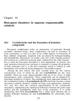
road transport (Figure 10.1). In the year 2000 there were 109 electric cars registered
in Germany out of 3,378,343 total (0.003%). Why do we talk about EVs at all?
Electricity is widely used in nearly all industrial and private areas because it can
be converted easily into heat, light, and motion and runs all electric devices.
Electricity is convenient, clean where it is used, and economical. To an increasing
extent it is used with batteries in telephones, computers, tools, etc., independent from
the direct connection to a power plant.
Electric motors with inverters using modern power electronics have the perfect
characteristics for city vehicles. Due to the high torque from zero speed no clutch
is necessary. Overload capability for acceleration makes an 18-kW electric motor
more dynamic than a 42-kW gasoline engine (Figure 10.2). Electric vehicl es are
quiet, have no emissions and offer the option to use any renewable primary energy
for mobility.
The only reason for whi ch electric vehicles are used to the very limited extent
they are now is the battery—the key component for the performance and autonomy
of electric vehicles. In the following chapters those battery systems will be described
that offer a specific energy of about 100 Wh/kg. This specific energy is necessary for
the minimum range of 100 km in Europe or 100 miles in the United States under all
normal driving conditions for a marketable electric vehicle. Figure 10.3 shows a
substitution potential of 25% of cars in private households if the vehicle range is
Copyright © 2003 by Expert Verlag. All Rights Reserved.
Figure 10.1 30 years EV registrations in Germany. (From Ref. 1.)
Figure 10.2 Torque and power characteristic of an electric motor with rated power of
18 kW and a 1.4 L gasoline engine. (From Ref. 2.)
Copyright © 2003 by Expert Verlag. All Rights Reserved.
100 km without a change in the mobility behavior of the users. This is the result of an
empirical mobility study [3].
As soon as such a battery is available in sufficient quantities and at a
reasonable price, electric vehicles will be available at least for urban transportation.
A cost comparison to conventional vehicles is presented in Section 10.7.2. Table 10.1
gives an overview of potential candidates from the present point of view.
10.2 ZEBRA BATTERY (Na/NiCl
2
)
10.2.1 Technology
ZEBRA batteries use Ni power and plain salt for the electrode material; the
electrolyte and separator is b
00
-Al
2
O
3
-ceramic; which is conductive for Na
þ
ions but
an insulator for electrons [4].
This sodium ion conductivity has a reasonable value of 50.2 O
À1
cm
À1
at
260 8C and is temperature dependent with a negative gradient [5]. For this reason the
operational temperature of ZEBRA batteries has been chosen in the range of 270 to
350 8C.
Figure 10.4 illustrates the principle. During charge the salt (NaCl) is
decomposed to sodium (Na) and chlorine (Cl). The sodium is ionized; one electron
from the m3 shell is conducted by the charger to the higher potential of the anode
(minus pole), where it recombines with the sodium ion (Na
þ
) which was conducted
through the b
00
-Al
2
O
3
electrolyte. The free chlorine reacts with nickel (Ni) in the
vicinity to form nickel chlorine (Ni Cl
2
) as a thin layer that covers the nickel grains.
Figure 10.3 Substitution potential of electric vehicles dependent on the vehicle range
without change of mobility behavior. (From Ref. 3.)
Copyright © 2003 by Expert Verlag. All Rights Reserved.
Table 10.1 EV battery systems.
System Pb/Pbo NiMH Na/NiCl
2
Na/S Li-ion LPB
Operating temperature (8C) <45 <45 235–350 285–330 <50 60–80
Electrolyte H
2
SO
4
KOH b
00
-ceramic b
00
-ceramic LiPF
6
Polyethylene oxide
Cell OCV (V) 2.0 1.2 2.58 2.1 4.0 4.0
Specific energy (Wh/kg) 25–35 40–60 100–120 110 80–120 100–120
Energy density (Wh/L) 50–90 120–160 160–200 135 200 200
Specific power (W/kg) 150 Up to 1000 150–180 <75 500–800 300–400
Comments Largest use
a
EV battery Stationary
b
a
Very high power cells for power assist HEV are available.
b
Li-ion batteries can be optimized for high power or high energy.
Copyright © 2003 by Expert Verlag. All Rights Reserved.
The reverse reaction during discharge is only possible by ionization of the
sodium; the sodium ion is conducted back through the b
00
-Al
2
O
3
electrolyte to the
cathode, whereas the electron now delivers its energy that was previously taken from
the charger to the load. In the cathode it recombines with the sodium to form salt
and nickel again.
There is no side reaction and therefore the charge and discharge cycle has 100%
charge efficiency; no charge is lost. This is due to the ceramic electrolyte.
The cathode has a porous structure of nickel and salt which is impregnated
with NaAlCl
4
, a 50/50 mixture of NaCl and AlCl
3
. This salt liquefies at 154 8C, and
in the liquid state it is conductive for sodium ions. It has the following functions,
which are essential for ZEBRA battery technology:
1. Sodium ion conductivity inside the cathode. The ZEBRA cells are
produced in the discharged state. The liquid salt NaAlCl
4
is vacuum
impregnated into the porous nickel/salt mixture that forms the cathode. It
conducts the sodium ions between the b
00
-Al
2
O
3
ceramic surface and the
reaction zone inside the cathode bulk during charge and discharge and
makes all cathode material available for energy storage. It also provides a
homogenous current distribution in the ceramic electrolyte.
2. Low resistive cell failure mode. Ceramic is a brittle material and may
have a small crack or may break. In this case the liquid salt NaAlCl
4
gets
into contact with the liquid sodium (the melting point of sodium is 90 8C)
and reacts to salt and aluminum:
NaAlCl
4
þ 3Na?3NaCl þ Al
In case of small cracks in the b
00
-alumina the salt and aluminum closes the
crack. In case of a large crack or break the aluminum formed by the above
Figure 10.4 ZEBRA chemistry.
Copyright © 2003 by Expert Verlag. All Rights Reserved.
reaction shorts the current path between plus and minus so that the cell
goes to low resistance. By this means long chains of 100 or 200 cells only
lose the voltage of one cell (2.58 V) but can continue to be operated. The
ZEBRA battery is cell-failure tolerant. It has been established that 5 to
10% of cells may fail before the battery can no longer be used.
This same reaction of the liquid salt and liquid sodium is relevant for the
high safety standard of ZEBRA batteries: In case of mechanical damage of
the ceramic separator due to a crash of the car the two liquids react in the
same way, and the salt and aluminum passivates the NiCl
2
cathode. The
energy released is reduced by about 1/3 compared to the normal discharge
reaction of sodium with nickel chloride.
3. Overcharge reaction. The charge capacity of the ZEBRA cell is
determined by the quantity of salt (NaCl) available in the cathode. In
case a cell is fully charged and the charge voltage continues to be applied to
the cell for what ever reasons, the liquid salt NaAlCl
4
supplies a sodium
reserve following the reversible reaction
2NaAlCl
4
þ Ni $þ2Na þ 2AlCl
3
þ NiCl
2
This overcharge reaction requires a higher voltage than the normal charge,
as illustrated in Figure 10.5. This has three practical very welcome
consequences:
Figure 10.5 ZEBRA open circuit voltage (OCV) depending on the status of charge (SOC).
Copyright © 2003 by Expert Verlag. All Rights Reserved.
(a) Any further charge current is stopped automatically as soon as the
increased open voltage equalizes the charger voltage.
(b) If cells are failed in parallel strings of cells in a battery, the remaining
cells in the string with the failed cells can be overcharged in order to
balance the voltage of the failed cells.
(c) For a vehicle fully charged in mountainous conditions there is an
overcharge capacity of up to 5% for regenerative breaking so that the
break behavior of the vehicle is fundamentally unchanged.
4. Overdischarge reaction. From the very first charge the cell has a surplus
of sodium in the ano de compartment so that for an overdischarge
tolerance sodium is available to maintain current flow at a lower voltage,
as indicated in Figure 10.5. This reaction is equal to the cell failure reaction
but runs without a ceramic failure.
10.2.2 ZEBRA Cell Design and Production
ZEBRA cells are produced in the discharged state so that no metallic sodium can be
handled. All the required sodium is inserted as salt. Figure 10.6 shows the cell design.
The positive pole is connected to the current collector, which is a hair-needle shaped
wire with an inside copper core for low resistivity and an outside nickel plating so
that all material in contact with the cathode is consistent with the cell chemistry.
The cathode material in form of a granulated mixture of salt with nickel
powder and traces of iron and aluminu m is filled into the b-alumina tube
(Figure 10.7). This tube is corrugated for resistance reduction by the increased
surface and is surrounded and supported to the cell case by a 0.1-mm-thick steel
sheet that forms a capillary gap surrounding the b-alumina tube. Due to capillary
force the sodium is wicked to the top of the tube and wets it independently of the
sodium level in the anode compartment.
Figure 10.6 Typical ZEBRA cell design.
Copyright © 2003 by Expert Verlag. All Rights Reserved.
The cell case is formed out of a rectangular tube continuously welded and
formed from a nickel-coated steel strip and a laser-welded bottom cap. The cell case
forms the negative pole.
The cell is hermetically sealed by laser-welded nickel rings that are
thermocompression bounded (TCB) to an a-alumina collar which is glass brazed
to the b-alumina tube.
10.2.3 ZEBRA Battery Design and Production
ZEBRA cells can be connected in parallel and in series. Different battery types have
been made with one to five parallel strings, up to 220 cells in series, and 100 to 500
cells in one battery pack. The standard battery type Z5 (Figure 10.8) has 216 cells
arranged in one (OCV ¼ 557 V) or two (OCV ¼ 278 V) strings. Between every second
cell there is a cooling plate through which ambient air is circulated (Figure 10.9),
providing a cooling power of 1.6 to 2 kW. For thermal insulation and mechanical
support the cells are surrounded by a double-walled vacuum insulation typically
25 mm thick. Light plates made out of foamed siliconoxide take the atmospheric
pressure load. This configuration has a heat conductivity of only 0.006 W/mK and is
stable for up to 1000 8C.
Figure 10.8 Standard ZEBRA battery type Z5C.
Figure 10.7 Beta-alumina tube.
Copyright © 2003 by Expert Verlag. All Rights Reserved.
10.2.4 Battery System Design
Figure 10.10 illustrates all components of the complete system ready for assembly.
The ohmic heater and the fan for cooling are controlled by the battery management
interface (BMI) for thermal man agement. Plus and minus poles are connected to a
main circuit breaker that can disconnect from outside the battery. The circuit
breaker is also controlled by the BMI.
Figure 10.10 ZEBRA battery system.
Figure 10.9 Z5C battery cooling plates.
Copyright © 2003 by Expert Verlag. All Rights Reserved.
The BMI measures and supervises voltage, current, status of charge, and
insulation resistance of plus and minus to ground and also controls the charger by a
dedicated PWM signal. A CAN-bus is used for the communication between the
BMI, the vehicle, and the electric drive system. All battery data are available for
monitoring and diagnostics with a notebook computer.
A multibattery server is designed for up to 16 battery packs to be connected in
parallel in a multibattery system with 285 kWh/510 kW using Z5C batteries.
10.2.5 ZEBRA Battery Performance and Life Data
ZEBRA cells and batteries are charged in an IU characteristic with a 6-h rate for
normal charge and a 1-h rate for fast charge. The voltage limitation is 2.67 V/C for
normal charge and 2.85 V/C for fast charge. Fast charge is permitted up to 80%
SOC. Regenerative breaking is limited to 3.1 V/C and 60 A/C so that high
regenerative breaking rates are possible.
The peak power during discharge, defined as the power at 2/3 OCV, is
independent of SOC so that the vehicle performance and dynamic is constant over
the whole SOC range [6]. Obviously this is important for practical reasons. Typical
battery parameters are summarized in Figure 10.8.
Battery life is specified as calendar life and cycle life. The calendar life of 11
years is demonstrated. The cycle life is measured by the accumulation of all
discharged charge measured in Ah divided by the nameplate capacity in Ah, so that
one nameplate cycle is equivalent to a 100% discharge cycle. This is a reasonable unit
because of the 100% Ah efficiency of the system. Furthermore 100% of the
nameplate capacity is available for use without influence on battery life. The
expected cycle life is up to 2500 nameplate cycles.
10.2.6 Battery Safety
Battery safety is essential, especially for mobile applications keeping in mind that
each battery should store as much energy as possible, but this energy must not be
released in an uncontrolled way under any conditions. It is required that even in a
major accident there is no additional danger originating from the battery. Many
different tests are performed to ensure safety, e.g., crash tests of an operative battery
against a pole at 50 km/h (Figure 10.11), overcharge tests, overdischarge tests, short
circuit tests, vibration tests, external fire tests, and submersion tests of the battery in
water have been specified and performed [7]. The ZEBRA battery passed all these
tests because it employs a four-barrier safety concept [8,9]:
1. Barrier by the chemistry. In case of severe mechanical damage of the
battery the brittle ceramic breaks, whereas the cell case made out of steel is
deformed and most likely remains closed. In any case the liquid electrolyte
reacts with the liquid sod ium to form salt and aluminum equal to the
overcharge reaction described above. These reaction products form a layer
covering the NiCl
2
cathode and thus passivate it. This reaction reduces the
thermal load by about 1/3 compared to the total electrochemically stored
energy.
Copyright © 2003 by Expert Verlag. All Rights Reserved.
2. Barrier by the cell case. The cell case is made out of steel with glass-
brazed thermocompression-bounded seal that remains closed for tempera-
tures up to about 900 8C.
3. Barrier by the thermal enclosure. The thermal isolation material of the
battery box is made out of foamed SiO
2
which is stabl e for above 1000 8C.
In combination with vacuum like a thermus it has a heat conductivity of
only 0.006 W/mK. This value is increased only by a factor of 3 without
vacuum. Beyond its primary function of thermal enclosure it is a protective
container for all fault or accident conditions.
4. Barrier by the battery controller. The battery controller supervises the
battery and stops operation in any undesired situation.
10.2.7 Recycling
Nowadays any product that is introduced to the market has to be recycled at the end
of its usage. ZEBRA batteries are dismantled. The box material is stainless steel and
SiO
2
, both of which are recycled by established processes. The cells contain Ni, Fe,
salt, and ceramic. For recycling they are simply added to the steel melting process of
the stainless steel production. Nickel and iron are contributed to the material
production and the ceramic and salt is welcome to form the slag. The recycling is
certificated and cost effective.
Figure 10.11 ZEBRA battery crashed against a pole at 50 km/h.
Copyright © 2003 by Expert Verlag. All Rights Reserved.
10.2.8 Applications
The ZEBRA battery system is designed for electric vehicles (Figure 10.12) which
require a balance of power to energy of about 2, e.g., a 25 kWh battery has about
50 kW peak power. Other applications are electric vans, buses, and hybrid buses with
ZEV range (Figures 10.13 and 10.14).
The present generation of ZEBRA batteries is not applicable for hybrid
vehicles that have a small battery of about 3 kWh but high power up to 60 kW (a
power to energy ratio of 15 to 20). Recently also prototypes for stationary
applications have been constructed. These have great advantages in hot climates and
for frequent cycling, where the lifespan of conventional batteries is reduced such that
the two- to three-times higher price of ZEBRA batteries is overcompensated by its
much longer life, resulting in lower life cycle cost and avoiding the exchange of
batteries. For uninterrupted power source (UPS) applications the float voltage of
2.61 V/cell for ZEBRA batteries has been established.
10.3 NaS BATTERY
10.3.1 Technology
Sodium-sulfate batteries use metallic sodium and sulfur, both in the liquid state, for
the electrode material and are assembled in the charged state. The electrolyte and
separator is b
00
-Al
2
O
3
-ceramic as in the ZEBRA battery (Fig. 10.13). During
discharge the sodium is conducted through the b-alumina to react with sulfur to
form Na
2
S
n
with 3 < n < 5. For charge the same reaction is reversed. The main
components of the NaS cell are shown in Figure 10.14. The negative pol e is
connected to the sodium container in the center of the cell, which is made out of
stainless steel. This container has a small hole at the bottom which is designed to
limit the sodium flow in case of overheating or overvoltage. The container is
Figure 10.12 Electric vehicles.
Copyright © 2003 by Expert Verlag. All Rights Reserved.
Figure 10.14 NaS cell components. (From Ref. 10.)
Figure 10.13 NaS battery chemistry.
Copyright © 2003 by Expert Verlag. All Rights Reserved.
surrounded by a deep drawn safety insert in aluminum, which has a tight fit to the
inner shape of the b-Al
2
O
3
tube in order to form a capillary gap for the wetting of the
ceramic electrolyte. The ceramic tube is hermetically sealed with a thermocompres-
sion-bound (TCB) seal to the negative and positive poles, which are formed by the
cell case. The sulfur is contained in the space between the ceramic tube and the cell
case. Sulfur and, in a partially discharged state, polysodium sulfur are both
electrically nonconductive so that a carbon-felt is integrated for conductivity. The
cell case is made out of aluminum and the inside coated with a conductive layer for
corrosion protection.
The NaS cells now being produced by the Japanese company NGK Insulators
have 632 Ah and 340 kWh/m
3
. 320 of such cells have been connected in parallel and
in series to form modules with 375 kWh and 3500 kg weight. These modules are
connected together for load leveling and power quality plants with up to 6 MW/
48 MWh. About 50 of such plants are in operation, the oldest since 1992.
Initially NaS batteries were developed for mobile and stationary applications.
But during abuse testing and simulations of heavy accidents the sodium and sulfur
reacted in an uncontrolled way and toxic gas was identified. For this reason NaS
batteries are no longer considered for mobile applications, but only for stationary
load leveling where damage due to accidents need not be considered (Figure 10.15).
10.4 LITHIUM-ION BATTERY
10.4.1 Technology
Lithium is a light and very reactive metal so that it is attractive for electrochemical
energy storage if a stable electrolyte can be found. There are different Li salts used
that are solved in nonaquatic solvents like methyl acetate or methyl formate. The
positive electrode is LiCoO
2
, which is mostly used today, but for car battery
applications it is too expansive. LiNiO
2
and LiMn
2
O
4
are under investigation and
should lead to lower cost, but have less energy density.
The negative electrode is intercalated carbon that can store Li up to C
6
Li. The
principle is shown in Figure 10.16.
Rechargeable Li-ion batteries were introduced to the market for consumer
products like mobile phones and notebooks. For electric vehicles up to now only
experimental cars have been demonstrated [12]. The main open tasks are related to
safety under abusive conditions and cost. Li-ion batteries can be designed for high
power or high energy (Table 10.1). It can be expected that they will be a candidate
for 42-V car systems as soon as safety and cost levels are satisfactory.
10.5 LITHIUM–POLYMER BATTERY
Lithium–polymer batteries (LPBs) use intercalated carbon for the negative electrode,
a polymer electrolyte, and metallic lithium that is de posited as a thin film as the
negative electrode. This battery type is under development but not yet introduced to
the market for electric vehicles.
Copyright © 2003 by Expert Verlag. All Rights Reserved.
Figure 10.16 Schematic of a Li-ion battery. (From Ref. 8.)
Figure 10.15 NaS battery load levelling plant built by NGK Insulators (Japan).
Copyright © 2003 by Expert Verlag. All Rights Reserved.
10.6 OTHER BATTERY SYSTEMS
For completeness Zn-halogen and redox batteries should be mentioned. These types
of batteries have the advantage of the ability to separate the electrolyte from the
storage of an electrode material that is liquid and can be stored in tanks
(Figure 10.17). By this means power and energy content are independent from one
another. For mobile applications this battery type no longer has any relevance due to
safety concerns. In case of accident the liquid could be spilled out and, e.g., bromine
would be liberated. But for stationary applications the pos sibility to store large
quantities of energy in tanks separate from the power-determining electrolyte
justifies the leak detection effort. Therefore, redox battery systems are still under
consideration for stationary electric energy storage.
Figure 10.17 Principle of the Zn/halogen accumulator with two different electrolyte
circuits.
Copyright © 2003 by Expert Verlag. All Rights Reserved.
10.7 BATTERY OVERVIEW
10.7.1 Minimum Requirements for EV Batteries
From mobility studies [13] it has been well established that the average distance
driven in cars per day is 40–60 km and 40–60 miles in the United States, subdivided
into 3.8 trips. At least during the introduction phase it cannot be assumed that public
charging stations will be available and that the drivers are willing and able to plan
their trips with such accuracy and detail that charging between trips during the day is
acceptable. Therefore, the strategy for the introduction of electric vehicles can only
be to charge at night and drive during the day. Therefore, the autonomy of EVs has
to be 60 km (60 miles in the United States) plus a reserve of 30 to 40%. EV fleet tests
[14] have shown that normal EV drivers use 60 to 70% of their capacity independent
of the range because they feel comfortable only with a sufficient reserve. These above
facts lead to the requirement of at least a 100-km range under any conditions, like
severe weather. The other fundamental requirement is a top speed of 100 km/h
because vehicles for urban traffic also use motorways where trucks are driving at
80 km/h and it must be possible to overtake them with a sufficient speed difference.
Figure 10.18 shows the range of a typical EV depending on its speed for three
typical specific energy values of batteries. From this it is obvious that the battery of a
marketable electric vehicle has to have about 100 Wh/kg as its minimum.
For the other requirements of safety, vibration resistance, climate, etc., the
reader is referred to Chapter 4, Sec. 4.4.
Figure 10.18 Range of electric vehicles depending on the speed and battery specific energy.
Copyright © 2003 by Expert Verlag. All Rights Reserved.
10.7.2 ZEV Life Cycle Costs Start to Be Competitive
A car for urban use drives typically 10,000 to 15,000 km per year for about 10 years
so that the operating cost for 150,000 km should be considered. All investigations on
vehicle cost indicate that the electric car cost without the battery is equal to or even a
little less than a comparable thermal engine car, whereas for operation electricity is
cheaper than fuel. Figure 10.19 shows that EVs reach breakeven cost at a fuel price
of 1 EUR/L and a battery price of 300 Euro/kWh. For ZEBRA batteries the
necessary battery life of 10 or more years and 1000 or more nameplate cycles have
been demonstrated. It can be expected that the battery will last as long as the vehicle.
Another option is battery rental, for which the monthly rental fee is paid out of the
energy cost difference between electricity and fuel. For electric vehicles the
maintenance costs (no oil replacement, nearly no break disk exchange due to
electric regenerative breaking, no exhaust pipe replacement) irrespec tive of the
energy costs and the assurance costs are less than for conventional cars.
These conditions are beginning to be realistic due to rise of crude oil price and
the beginning of series production of at least the ZEBRA battery. Now electric
vehicles are starting to become an option for urban traffic, about 100 years after their
first period of success.
10.8 FUEL CELLS
Fuel cells have been known about for more than 150 years [15]. W. R. Grove
operated the first fuel cell in his laboratory by 1842, 17 years before G. Plante
´
built
the first lead-acid accumulator. However, they never could compete with the
thermomechanical process for electricity production. But they are being rediscovered
nowadays because they offer the possibility to convert chemical energy to electricity
Figure 10.19 EV battery and electricity cost compared to fuel cost.
Copyright © 2003 by Expert Verlag. All Rights Reserved.
directly unconstrained by the Carnot efficiency. The different types of fuel cells are
listed in Table 10.2.
The main effort of recent development work and investment is concentrated on
the industrialization of PEM and SOFC type fuel cells. Both have advantages and
disadvantages: PEM fuel cells are operated at a convenient low temperature of 80 8C,
can be started from ambient temperature, and the technology is mature for first field
tests. Its important disadvantage is that it operates only with pure H
2
as its fuel,
which is not a generally available secondary energy with an existing infrastructure.
The use of PEM fuel cells for electric vehicles requires the solution of another issue,
the production, distribution and storage of hydrogen in large scale. SOFCs operate
with any fuel because its ceramic electrolyte conducts oxygen ions that ‘‘burn’’ any
fuel. The disadvantage is the high operating temperature of 500 to 900 8C. A small
unit for about 5 kW is under development.
Actually there is a large interest in fuel cells and many updated publications are
available [16,17]. For this reason a more detai led presentation of this subject is not
attempted in this chapter.
REFERENCES
1. Statistische Mitteilungen des Kraftfahrtbundesamtes, 2002.
2. R Bady. Technisches Einsatzpotential von Elektrofahrzeugen mit Hochtemperatur-
batterien im sta
¨
dtischen Alltagsbetrieb. Dissertation, Schriftenreihe Automobiltechnik,
RWTH Aachen, 2000.
3. H Hautzinger, B Tassaux-Becker. Vergleichende Untersuchungen zur erforderlichen
Reichweite von Elektroautos fu
¨
r den deutschen und amerikanischen Markt. Institut fu
¨
r
Angewandte Verkehrs- und Tourismusforschung e.V., Heilbronn, Ma
¨
rz, 1994.
4. JT Kummer. Beta-alumina electrolytes. H Reiss, JO McCaldin, eds. Progress in Solid
State Chemistry. New York: Pergamon Press, 1972, pp. 141–175.
5. JL Sudworth, AR Tilley. The Sodium Sulphur Battery. London: Chapman and Hall,
1985.
6. DAJ Rand, R Woods, RM Dell. Batteries for Electric Vehicles. Austin, TX: Research
Studies Press, 1998.
7. H Bo
¨
hm, RN Bull, A Prassek. ZEBRA’s response to the new EUCAR/USABC abuse
test procedures. EVS-15, Brussels, Sept. 29 to Oct. 3, 1998.
8. Av Zyl, C-H Dustmann. Safety aspects of ZEBRA high energy batteries. evt95, Paris,
Nov. 13–15, 1995, p 57.
Table 2 Different fuel cell types.
Type Electrolyte
Ionic
conduction Fuels T (8C)
SOFC ZrO
2
ceramic O
2 À
CH
4
, CO, H
2
500–900
MCFC NaCO
3
liquid CO
3 À
CO, H
2
650
AFC KOH liquid (OH)
À
Pure H
2
70
PAFC H
2
PO
4
liquid H
þ
H
2
200
PEM Polymer solid H
þ
Pure H
2
80
Copyright © 2003 by Expert Verlag. All Rights Reserved.
9. D Trickett. Current status of health and safety issues of sodium/metal chloride (ZEBRA)
batteries. National Renewable Energy Laboratory Report TP-460-25553, 1998.
10. NGK Insulators, Ltd. Nagoya, Japan.
11. R Busch, P Schmitz. The e-KA—an electric vehicle as technology demonstrator. EVS-18,
Berlin, Oct. 20–24, 2001.
12. H Hautzinger, B Tassaux-Becker, R Hamacher. Elektroauto und Mobilita
¨
t, Das
Einsatzpotential von Elektroautos. Forschungsbericht FE-Nr 70379/91, Institut fu
¨
r
Angewandte Verkehrs- und Tourismusforschung e.V., Heibronn, January 1992.
13. Final report of the demonstration project: testing of electric vehicles of the latest
generation on Ruegen Island. Deutsche Automobilgesellschaft Braunschweig, 1997.
14. AJ Appleby, FR Foulkes. Fuel Cells. New York: Van Nostrand Reinhold, 1989.
15. R Stobart. Fuel Cell Technology for Vehicles. SAE International, 2001.
16. JM DeCiocco. Fuel Cell Vehicles. SAE International, 2001.
Copyright © 2003 by Expert Verlag. All Rights Reserved.