Chapter 18 - Lithium Batteries: The Latest Variant of Portable Electrical Energy pdf
Bạn đang xem bản rút gọn của tài liệu. Xem và tải ngay bản đầy đủ của tài liệu tại đây (853.69 KB, 65 trang )
18
Lithium Batteries: The Latest Variant of
Portable Electrical Energy
W. JACOBI
18.1 INTRODUCTION
During the last two decades of the 20th century the lithium battery technique played
a more and more important part in the market,
1
at first for the more e xpensive
special applications as, e.g. the military and air- and spacecraft technologies. Its
technique is one of the more recent results of research and development in the fields
of applied electrochemistry. New products like lithium batteries were accessible
because of the progress in chemistry, physics, materials sciences, analytics,
measurement and control technology, and finally production technology, leading
to something new even if this was based on old ideas.
2
An impor tant stimulus for the new batteries was the need for small and
lightweight energy sources for portable electronic devices, which have become
smaller and smaller by the tremendous progress of miniaturization in our electronic
age. So the scientifically and technically manageable product found its wide market.
The miniaturization of consumer electronics and their mechanical parts has to be
addressed first.
1
The extensive overviews of Refs. 1, 5, 6, and 9 are recommended to everybody who is interested in more
electrochemical and technical details. In the past the battery industry regularly reported on lithium
batteries in Boca Raton, Florida, too (10).
2
The history of the lithium technology was described in more detail by Klaus Eberts in Ref. 11. Several
of his figures have been adopted in this article.
Copyright © 2003 by Expert Verlag. All Rights Reserved.
Some desirable or necessary applications became accessible for the first time by
lithium batteries: e.g. the cardiac pacemaker requires batteries with negligible self-
discharge and extremely high reliability for service periods of 5 to 10 years. A control
and display unit may be powered for all its service life of about 10 years by only one
(primary) battery, which needs not to be changed before the whole unit is replaced at
the end. Lithium batteries are able to power portable radio tranceivers under deep
arctic temperature conditions for weeks and months. Modern handheld mobile
phones and computers are usable for (many) hours with their lightw eight and small
rechargeable lithium accumulators.
In the following article we are first going to define what ‘‘lithium battery’’
means. The general advantages of its technology will then be presented. Related
mainly to the non-rechargeable lithium batteries, the chemistry and physics of
anode, cathodes , and electrolytes are described showing the details of the specific
lithium technology. Selected examples of lithium prima ry batteries, which have been
on the market for a long time, allow us to explain the details of the various technical
ways of their realization.
Following the primary batteries we deal with (rechargeable) secondary lithium
batteries, which within the last decade found their specific markets. Examples of
them will be described. Finally we will see which special components within the
battery system are needed, preferably when high rate versions are called for, which
procure the desired reliability and safety, and how – according to the battery type –
suitable ways are used for their disposal after the end of their life.
18.2 THE NAME ‘‘LITHIUM BATTERY"
The lithium battery family got its name from the metal of the anode (negative
electrode), lithium, which is the most lightweight metal, the third element of the
periodic system just behind hydrogen and helium. The Li/Li
þ
electrode is positioned
at the extreme negative end of the system of electrochemical elements. If combined
with counter-electrodes of a far positive potential, the lithium electrode produces a
very high open circuit voltage (OCV) and thus also a very high energy content in the
respective galvanic cells. Lithium is used for anodes as pure metal, alloyed with other
suitable metals, and as intercalation compounds. In practice, together with lithium, a
multiplicity of cathodic (positive electrode) materials (see Table 18.1) can build an
electrochemical energy store, whereas the requirements for primary and secondary
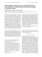
applications are different only in part. Figure 18.1 shows the discharge curves of a
selection of primary systems, which were then commercially available. Some of them
reached an enduring market position; others were hardly more than prototypes or
small series products.
The variety of electrolytes and electrolytic mixtures is comparable to that of the
cathodes they are used for. The wide variety of applications may be recognized from
the capacity range of industrialized products that reaches from a few mAh up to
10,000 Ah (Figure 18.2). The voltage of lithium cells is found between 1.5 and 4 V
depending on the cathodic material used (Figure 18.1).
Production and handling of lithium batteries require special techniques on
account of the specific features of the lithium metal and of some of the related
cathodic substances. Here one has to deal primarily with the reactivity of lithium
Copyright © 2003 by Expert Verlag. All Rights Reserved.
Table 18.1 Classification of lithium primary batteries according to cathodes and electrolytes.
Classification Electrolyte Power Capacity (Ah)
Temperature
range (8C)
Shelf life
(years)
Typical
cathodes Voltage (V) Characteristics
Solved Organic or Medium 0.5–20,000 À55–70 8–10 SO
2
3.0 High energy, high power,
cathodes inorganic to high W (150) SOCl
2
3.6 good deep temperature
(fluid, gas) SO
2
Cl
2
3.9 capability, long life
Solid state Organic Low to 0.01–10 À40–55 5–8 CrO
2
3.6 High energy, medium to low
cathodes medium, (200) V
2
O
5
3.3–2.3 power, no internal
mW Ag
2
CrO
4
3.1 overpressure
MnO
2
3.0
(CF)
X
2.6
S 2.2
Cu
4
O(PO
4
)
2
2.2
CuS 1.7
FeS
2
1.6
FeS 1.5
CuO 1.5
Bi
2
Pb
2
O
3
1.5
Bi
2
O
3
1.5
Solid Solid Very low 0.003–5 0–100 10–25 J
2
2.8 Very long life, very safe, very
electrolyte mW PbJ
2
1.8 low power
PbS 1.8
Source: Ref. 3.
Copyright © 2003 by Expert Verlag. All Rights Reserved.
with humidity and the main constituents of the atmosphere, i.e. nitrogen, carbon
dioxide, and oxygen.
18.3 THE LITHIUM BATTERY’S SPECIAL ADVANTAGES
For defined applications lithium batteries show remarkable advantages if compared
with traditional primary and secondary batteries.
Figure 18.1 Discharge graphs of various lithium primary batteries. (From Ref. 3.)
Copyright © 2003 by Expert Verlag. All Rights Reserved.
18.3.1 High Cell Voltage
Most lithium battery systems show a cell voltage in the upper range of 1.5 to 4.0 V or
even higher. This alone is an advantage with regard to the energy density and specific
energy of those cells. So in many cases only one lithium cell suffices where otherwise
two or three conventional Leclanche
´
or alkaline cells are necessary.
18.3.2 Energy Content by Weight: Specific Energy
The mass related (gravimetric) energy content, the ‘specific energy’ (SE) of lithium
batteries, is 100 to 500 Wh per kg depending on system and cell type. Preferably
portable devices profit from a lithium power supply. For comparison: classic lead-
acid batteries show a specific energy between 35 and 55 Wh/kg and NiCd batteries, a
bit more powerful, from 50 to 70 Wh/kg. The said higher (lithium) values have,
however, been only realized by primary systems until now.
18.3.3 Energy Content by Volume: Energy Density
The volumetric energy content, mostly understood as the ‘energy density’ (ED) , goes
from 300 to 1300 Wh/L. Lithium batteries therefore require less space than
conventional battery systems. Leclanche
´
cells, for example, deliver 165 and alkaline
cells 330 Wh/L.
Figure 18.2 Typical regions of performance of lithium primary batteries by type of
electrolyte and cathode (the upper right region has to be broadened up to 10,000,000 mAh at
10,000 A.) (From Ref. 3.)
Copyright © 2003 by Expert Verlag. All Rights Reserved.
18.3.4 Loadability
One can choose between lithium primary batteries tailor-made as high rate batteries
with a very low resistance for high loads or with a high resistance for low rate long-
time applications. Until now secondary systems have been available only in the low
capacity range for small and medium loads, i.e. with higher resistance.
18.3.5 Discharge Characteristic
Some lithium systems show an especially flat and stable curve (voltage against time)
for the discharge of the whole capacity. Thi s supports electronic devices which are
designed for little tolerances of their feeding voltages.
18.3.6 Deep Temperature Capability
These batteries may be stored and operated within an extremely wide temperature
range. For the first time especially the deep temperature range of À10 to À40 and
even À55 8C can be supported by them without any additional means such as heaters
or special insulation.
18.3.7 Shelf Life
Most of the lithium primary batteries may be stored for over 10 up to 20 years with
negligible self-discharge, so that they still deliver most of their nominal capacity.
They are continuously active, i.e. at all time ready for service. At normal temperature
storage only 5 to 10% self-discharge after 10 years is typical.
18.3.8 Environmental Compatibility
If compared to metals used for common batteries such as lead or nickel and
cadmium, lithium is not as poisonous as these to biological systems. Disposal of used
lithium batteries is therefore a smaller problem.
18.4 CHEMISTRY AND PHYSICS OF LITHIUM PRIMARY
BATTERIES
18.4.1 Properties of Anodic Metal Lithium
As can be seen by comparison with some other anodically used metals, lithium metal
is the anodic material with the highest capacity and energy contents related to weight
(Ah/kg and Wh/kg). It is number three in the periodic system of elements after
hydrogen and helium. It is the most lightweight of the lightweight metals, the alkali
metals. According to the rules of chemistry it behaves similarly as the other metals of
the same column of the periodic system, sodium and potassium. In the
electrochemical series of elements, which represents a measure of how ‘easily’ metals
and other redo x systems may offer or attract electrons, lithium occupies the extreme
left, or negative, position. The electrical potential of the redox system Li/Li
þ
related
Copyright © 2003 by Expert Verlag. All Rights Reserved.
to the standard hydrogen electrode is À3.040 V.
3
That means that the lithium atom
most readily gives up its outer valence electron. Combined with a suitable cathodic,
i.e. electron-attracting, material it results in a high cell voltage. The complete cell
reaction delivers an especially high amount of energy per formula turnover . So
lithium batteries are ‘high energy’ batteries.
The silver-white lithium metal is soft and ductile, similar to lead and can be
extruded or rolled into thin foils very easily. As long as it is not covered too much by
passivation layers it may be welded simply by pressure in cold state and also onto
copper as necessary, for example, for attachment of current collector tabs to the
lithium electrode. Lithium readily reacts with water and air, similar to the other
alkali metals, but not exactly as spontaneously and vigorously as its homologize
sodium and potassium. Nonetheless the pure metal requires climate chambers of
extremely dry air for handling.
4
In normal atmosphere on a fresh metallic surfa ce of
lithium a protective layer grows up from lithium hydroxide, lithium oxides, and
lithium carbonate and – at normal humidity (water acts here in a catalytic manner) –
mostly from the nitrogen compound Li
3
N. These lithium compounds generate an
extremely dense reaction layer, a so-called passivation layer, which is generally well
known especially from aluminium and which in turn gives the essential condition for
the technical applicability of aluminium. Without that passivation layer, a
component made of aluminium would be destroyed very quickly under atmos pheric
conditions.
5
The lithium’s cap ability for passivation is advantageous for the said
long shelf-life of lithium (primary) batteries. Also the concept of the fluid cathodes is
possible only by passivation. Of course lithium as the pure soft metal is of no
common mechanical use as aluminium.
So the very important advantage of the long shelf-life of lithium batteries
depends on both its passivation ability not only in atmosphere, but also in suitable
electrolytes. In spite of the passivation film the lithium electrode may be ‘activated’
quickly and easily: On an electrical load the layer breaks down very quickly within
seconds or fractions thereof. High current densities may then be realized. On the
other hand the passivation film in a cell without load hinders self-discharge by
unwanted side reactions of the anodic metal with components (or even
contaminants) of the electrolyte. This strongly hindered but not absolutely excluded
self-discharge of cells not under load during shelf-life has to be understood as the
further growth of the passivation layer, which proceeds as a solid-state reaction only
extremely slowly. So shelf-lives of 10 to 20 years are possible under consumption of
only 10 to 20% of the active metal. Depending on the special battery system, the
3
The potential of a single electrode is defined as the energy or work to be done for the transport of an
elementary electrical charge (massless) from the virtual free space into the phase under consideration. This
cannot be measured, as everybody knows. It normally is handled as the difference between the potentials
of the electrode and a reference electrode, most often the standard hydrogen electrode (SHE).
4
The standard condition is at a dew point (water) of À30 8C. This corresponds to water in air
concentration of less than 2% of relative humidity at normal temperature.
5
A passivation layer is a dense mechanically stable layer from compounds of the metal being protected
and, e.g., oxygen, hydroxyl ions – from water – carbon dioxide CO, sulfuric acid H
2
SO
4
, and other
components, preferably from the air. This passive layer – once grown – keeps off the said reactants from
further direct access to the metal. Further reaction is possible only as ‘solid state reaction’, which proceeds
by several powers of ten more slowly than the first or ‘direct’ reaction of the unprotected surface.
Copyright © 2003 by Expert Verlag. All Rights Reserved.
passivation layer consists of lithium chloride, lith ium dithionite, lithium hydroxide,
or also of lithium alcoholates, carbonate, and others, i.e. generally lithium and parts
of the actual electrolyte mix.
Lithium is most often refined from the mineral spodumen.
6
Similarly to
aluminium the refinement is done by electrolysis. It is consequently rather expensive
but until now its availability has not been limited.
The energy density, measured as Wh/L, of the lithium electrode alone is not
especially high. It is even slightly lower than the corresponding value of the classic
battery material lead and remarkably lower than that of aluminum.
7
The reason is
that even at extremely different atomic weights the atomic volumes of these three are
relatively similar at about 10 to 20 cm
3
/g atom, but during discharge lithium provides
only one, lead two, and aluminium three electrons per metal atom. For comparison
Table 18.2 gives a collection of the so-called equivalent volumes
8
of lithium and
some other anodic metals which were used traditionally for batteries and
accumulators. On the other hand the specific energy of lithium, measured as Wh/
kg, is on top of the anodic materials considered. The energy content – both ED and
SE – of a complete cell depends of course on the particular cathodic partner and type
of housing and packing. So the theoretical data of the anode alone may not be
overestimated.
18.4.2 Electrolytes for Lithium Batteries
18.4.2.1 Organic Solvents with Ionic Salts
The electrolyte of a battery
9
, or rather of an electrochemical cell, is the mediator
between the reactions in parts which proceed at the two electrodes and which deliver
electrical energy out of the combined chemical process. Via the electrolyte the
different levels of electrical charge at cathode and anode in a cell under load are
levelled out. Its conductivity essentially contributes to the cell’s energetic efficiency.
For many lithium systems the electrolyte is made from an organic solvent and a salt
solved in it (electrolyte salt) – usually a lithium salt. The following requirements rule
the choice of the electrolyte for a lithium battery (see Table 18.3):
The dielectric constant (dc) of the solvent has to be as high as possible. The
higher the dc, the better the electrolyte salt is solvated, i.e. solved and dissociated.
In order to have solvated ions of the electrolyte salt as mobile as possible and
so to get a resistance for the current flow as low as possible, the viscosity of the
electrolytic fluid has to be as low as possible.
6
Spodumen or triphane LiAl (SiO
3
)
2
belongs to the catena silicates or pyroxenes. It is found in
pegmatites in the United States and also in Scotland and Austria.
7
Aluminum as an anode for battery applications in the field of marine and standby power was only
experimentally investigated recently.
8
The equivalent mass of an ion is defined as the fraction of the atomic or molecular weight of this ion
which carries one electrochemical equivalent, i.e. 96,450 Coulomb (Asec) of electrical charge. The
equivalent volume is defined correspondingly.
9
According to the official version the smallest unit of an electrochemical storage medium is a (galvanic)
‘cell’. Several cells make a ‘battery’. In this article ‘battery’ is often used colloquially when the term ‘cell’
would be more correct.
Copyright © 2003 by Expert Verlag. All Rights Reserved.
Generally the electrolyte of an electrochemical cell must not be electrolyzed, i.e.
degraded by the potential difference, the voltage between the electrodes. Aqueous
electrolytes with the degradation voltage of 1.23 V for the water molecule have to be
excluded regularly from use in lithium cells with cell voltages between 2.5 and nearly
4.5 V. The scheme of Figure 18.3 explains this with the model of the molecular orbital
(MO) and band theory
10
. The oxidation potential of the electrolyte has to be higher
than the potential of the anode (or than the Fermi energy of the anodic metal) and
the reduction potential has to be lower than the corresponding potential of the
cathode (Fermi edge of the cathodic material). Where this requirement is not fulfilled,
the thermodynamically demanded reaction between electrolyte and electrodes has to
be blocked at least kinetically as realized in the lead-acid accumulator with its
aqueous sulfuric acid electrolyte. The reactivity of the electrolyte’s components
against lithium (and the cathodic counterpart) has to be negligible to use the
electrode quantitatively for its electrochemical purpose and not to get it consumed in
a useless manner by self-discharge. A special case is the passivation of lithium in some
systems under open circuit conditions (cell without load) and its electrochemical
reactivity, i.e. discharge ability under load. This passivation is maintained by a very
thin but very stable layer of reaction products between the lithium and one of the
electrolyte’s components. This layer then protects the bulk metal against further
reaction. The passivation’s barrier can be overcome only very slowly as is normal for
a solid-state reaction. The electrochemical efficiency of the lithium anode for some
lithium primary systems is within 60 to 90%. In any case water and alcohols, i.e. all
protic solvents, have to be excluded from lithium cells, because they are not able to
produce a sufficien tly stable and really passivating layer.
The electrolyte should show a melt ing or solidification point as low as possible
together with low viscosity even at low temperatures for high conductivity and high
power. Typical limits for discharge of lithium batteries are between À40 and À55 8C.
Conductive salts for the electrolyte mixture are to be chosen with preferably
low lattice energy. So solvation is easy and a high percentage of the solute might be
dissociated in the solution. For most systems salts of lithium are chosen which are
combined with big complex anions such as, e.g. lithium perchlorate LiClO
4
, lithium
tetrafluoroborate LiBF
4
, lithium hexafluoroarsenate LiAsF
6
, lithium hexafluoropho-
Table 18.2 Specific data to determine the equivalent volumes of some anodic metals for
batteries.
Anodic metal Li Pb Al Zn Na
Cd
Maximal oxidation state Li
þ
Pb
2 þ
Al
3 þ
Zn
2 þ
Na
þ
Cd
2þ
Atomic weight (g) 6.939 207.19 26.98 65.37 22.99
112.40
Equivalent weight (g) 6.939 103.60 8.99 32.69 22.99
56.20
Specific gravity (g/ccm) 0.534 11.34 2.702 7.14 0.97
8.642
Equivalent volume (ccm/equiv.) 12.99 9.14 3.33 4.58 23.70
6.50
10
HOMO ¼ highest occupied molecular (or atomic) orbital – here of oxygen, LUMO ¼ lowest unoccupied
molecular (or atomic) orbital – here of hydrogen. The difference between them is the decomposition
voltage – here of water.
Copyright © 2003 by Expert Verlag. All Rights Reserved.
Table 18.3 Physical data of pure solvents used for lithium cells.
Name Abbreviation
Boiling
point (8C)
Melting
point (8C)
Dielectric
constant
Spec. gravity
(g cm
À3
)
Viscosity
(cP)
Acetonitrile AN 81.6 À45.7 35.95 0.777 0.34
g-butyrolactone BL 202 À43 39.1 1.13 1.75
1,2-dimethoxiethane DME 83 À58 7.2 0.859 0.46
N,N-dimethyl formamide DMF 153 À61 36.7 0.94 0.80
Dimethyl sulfoxide DMSO 189 18,5 46.6 1.10 1.96
1,3-dixolane 78 À95 1.06
Ethylenecarbonate EC 248 36 89 1.32 1.90 (40 8C)
Methyl formiate MF 31.5 À99 8.5 0.974 (20 8C) 0.35 (20.15 8C)
Nitromethane NM 101 À29 36 1.13 0.63
Propylene carbonate PC 241 À49 64 1.19 2.53
Phosphoroxichloride 105 1.2 13.7 1.645 1.06
Thionylchloride 78.8 À105 9.05 (22 8C)) 1.63 0.60
Sulfurylchloride 69.4 À54.1 9.15 (22 8C) 1.65 0.67
Tetrahydrofurane THF 66 À65 7.6 0.89 0.46
Copyright © 2003 by Expert Verlag. All Rights Reserved.
sphate LiPF
6
, lithium tetrachloroaluminate LiAlCl
4
. These anions seem to be big
ones according to the sim ple formula. But in the solution these negatively charged
ions are nonetheless relatively small because they are able to attract only a thin layer
of ‘‘solvate ions’’. Consequently they show a high mobility and hence a good
conductivity. The contrary is valid for the small central ion of lithium that is
surrounded by an over-proportionally thick layer of solvate molecules, thus showing
a reduced mobility and conductivity. In practice often electrolyte solutions with 1
mole electrolyte salt per liter are used.
But also under optimal conditions these electrolytes based on organic solvents
yield a conductivity of about 10
À2
ohm
À1
cm
À1
, which is by more than one power of
ten lower than in alkaline or acidic aqueous solutions.
18.4.2.2 Inorganic Electrolytes Acting as Cathodes
This class of electrolytes gives the technology of lithium primary batteries a special
exotic attraction. The fluid electrolyte mixture acts as the media of transfer of electric
charges between anode and cathode as described above. In addition it also contains
the cathodic active substance, which is in direct contact to the anodic counterpart,
the lithium metal, but nonetheless reacts separately in a distance from the anode at a
cathodic support electrode by consumption of electrons from the outer circuit. This
paradoxical behavior is possible because of the ‘‘cathode’s’’ ability to create a
Figure 18.3 Position of the decomposition energies of electrolytes relative to the potentials
of the anode (reductant is oxidized by discharge) and the cathode (oxidant is reduced by
discharge) of a galvanic cell for (a) solid electrodes with fluid electrolyte and (b) fluid
electrodes with solid electrolyte. (From Goodenough in Ref. 1.)
Copyright © 2003 by Expert Verlag. All Rights Reserved.
passivation layer on the lithium surface, which protects the metal against further
attack of the spontaneously (thermodynamically favore d) reacting ‘‘cathode’’ and
against quantitative self-discharge. On the other hand the passivation layer cracks if
the cell is electrically loaded.
Also these inorganic electrolytes or their mixtures with organic solvents have to
be polar, i.e. be constituted from molecular dipoles, and to show a high dielectric
constant, again for a high ability to solve and dissociate the lithium electrolyte salt
and the products of the discharge reaction.
The electrolytes acting as cathodes are mixed with a suitable electrolyte salt and
with or without an organic co-solvent. The most important examples are
thionylchloride with lithium chloride and sulfur dioxide with acetonitrile and
lithium bromide. The organic co-solvent again ensures low viscosity and low melting
points for good deep temperature operation.
With highly porous cathodic conductors battery systems with inorganic
cathodic electrolytes may deliver especially high power. These systems, which have
been proved for years, are operated under moderate (SOCl
2
: about 0.5 to 5 bars) and
high overpressure (SO
2
: 4 to 32 bars) in the cells.
18.4.2.3 Solid Electrolytes
Solid electrolytes generally have a far lower conductivity than fluids because of the
low ionic mobility, also in specially selected ionic crystals and other solids. The
higher resistance in such a cell allows therefore only very low loads. But otherwise
side reactions such as self-discharge – provided anode and cathode are also in the
solid state – run only extremely slowly if at all. From this basic low reactivity such
battery systems show especially high reliability also during shelf-lives and
operational times of many years.
One example is the lithium iodide electrolyte in a typical cardiac pacemaker
battery. Another one is the mixture of lithium halides with – for immobilization –
magnesium oxide in some thermal batteries, and a further one a mixture of lithium
iodide with aluminium oxide or silica for some memory back-up systems.
18.4.2.4 Electrolytes from Molten Salts
A difference between a molten substance and another fluid chemical of course simply
depends on the standpoint: Here we deal with substances which at normal conditions
– such as normal temperature – are in the solid state and are fluid only at elevated
temperatures when the battery is to operate. So we get battery systems whose
electrolyte in the solid state at normal temperature shows an extremely low
conductivity so that all self-discharge and other unde sired side reactions are in fact
frozen in.
With ‘thermal batteries’ such electrolytes are used combined with a tailor-made
rapidly acting pyrotechnic heating device. Typical temperatures of operation lie
between 200 and 500 8C, depending on the system. A molten salt electrolyte is used,
for example, in the lithium iron disulfide battery which is described below.
Copyright © 2003 by Expert Verlag. All Rights Reserved.
18.4.3 Cathodic Materials
Some substances commonly used for cathodes are shown in Table 18.4 explaining
some important features.
18.4.3.1 Solid Cathodes: Intercalation Compounds and Others
Lithium intercalation compounds are preferably suitable for use as cathodes. The
tiny lithium ion is easily inserted into and released from a certain number of
inorganic solids at a potential that lies at positive values on the electrochemical series
far away from the Li/Li
þ
electrode. The lithium ion’s small volume affects the host
structure only slightly. The intercalation is merely not hindered so that this process is
mostly reversible and hence suitable for recharg eable batteries.
18.4.3.2 Fluid Depolarizers
Table 18.4 also contains those substances, which are used in the fluid state at normal
temperatures for cathodes. Their features were already described when we dealt with
them as electrolytes. They are used with and without a co-solvent, they build up on
the lithium metal’s surface stable passivation layers which are cracked only under
electrical load when during discharge lithium ions leave the surface. These
‘‘cathodes’’ are especially powerful if combined with highly porous cathodic
conductors.
When a co-solvent is not needed – as in thionylchloride batteries – the system
with the fluid depolarizer realizes an especially high energy densit y because this
electrochemically non-active component of the co-solvent is avoided.
18.5 DESIGNS AND TECHNOLOGY OF PRIMARY LITHIUM
BATTERIES
Lithium cells have to be hermetically sealed. Intrusion of atmospheric humidity is
not allowed. On the other hand some of the cell components are not allowed to
escape because of their aggressiveness and their high vapor pressure. This is obvious
for sulfur dioxide for instance. The cell geometry is governed by mechani cal
requirements both from the standpoint of the manufacturing technique and the
application. There are prismatic, cubic, and flat formats in different dimensions with
cubic or circle shaped electrode stacks. There are preferably round cells, which
contain the electrodes either in cylindrically wound or bobbi n versions. In the case of
the pressurized cell types, the round can is of course the most economic version of a
pressure vessel.
The lithium anode is used in the pure metallic state as thin extruded or rolled
foil with a thickness down to 25 mm or as a massive block, depending on the load to
be applied. In special cases the lithium is applied also in alloys or, as in rechargeable
batteries, in intercalation
11
compounds.
11
See also the description of the rechargeable lithium batteries in Section 18.7.
Copyright © 2003 by Expert Verlag. All Rights Reserved.
Table 18.4 Physical and electrochemical data of some cathodic materials for lithium batteries.
Cathodic Molecular Valences Specific
Electrochemical equivalent
Calc. cell
voltage
material weight involved gravity (g cm
À3
) (Ah g
À1
) (Ah cm
À3
)(gAh
À1
) (against Li) (V)
SO
2
64 1 1.37 0.419 — 2.39
3.1
SOCl
2
119 2 1.63 0.450 — 2.22
3.65
SO
2
Cl
2
135 2 1.66 0.397 — 2.52
3.91
Bi
2
O
3
466 6 8.5 0.35 2.97 2.86
2.0
Bi
2
Pb
2
O
5
912 10 9.0 0.29 2.64 3.41
2.0
(CF)
n
(31)
n
1 2.7 0.86 2.32 1.16
3.1
CuCl
2
134.5 2 3.1 0.40 1.22 2.50
3.1
CuF
2
101.6 2 2.9 0.53 1.52 1.87
3.54
CuO 79.6 2 6.4 0.67 4.26 1.49
2.24
CuS 95.6 2 4.6 0.56 2.57 1.79
2.15
FeS
2
119.9 4 4.9 0.89 4.35 1.12
1.8
MnO
2
86.9 1 5.0 0.31 1.54 3.22
3.5
MoO
3
143 1 4.5 0.19 0.84 5.26
2.9
Ag
2
CrO
4
331.8 2 5.6 0.16 0.90 6.25
3.35
V
2
O
5
181.9 1 3.6 0.15 0.53 6.66
3.4
Source: Ref. 8.
Copyright © 2003 by Expert Verlag. All Rights Reserved.
For separation many systems with fluid electrolytes use a micro-porous foil
from polypropylene known as Celgard
1
. Alternatives are fluorinated hydrocarbons
(e.g. Halar
1
) or glass fiber nonwovens.
Cathodes are made from a paste of the cathodic active material with binders
and electronically conductive additives, which are rolled onto metallic foils or exmets
from nickel or aluminium . These cathodes are used as flat electrodes or in spirally
wound form. The bobbin form realizes the same design in principle, but the layers of
the active materials are much thicker, which in turn reduces the typical load to be
applied to these bobbin cells. For fluid depolarizers the cathodic conductor often
carries a mixture of carbon black with Teflon
1
binder, which is impregnated with
catalytically active substances.
Containers of lithium batteries are mostly made from stainles s steel.
Depending on the internal pressure of the system, the contai ners are round cells of
IEC standard formats or of proprietary geometry or with prismatic rectangular
geometry (also button cells and circle shaped bigger cells and special geometries as
for cardiac pacemakers have been realized). These cells are mostly hermetically
sealed by welding or – in case of negligible inner pressure – crimp-sealed with
polymer gaskets.
For the electrical contacts in many cases the metallic container is one pole and
a glass-to-metal seal (or ceramic-to-metal seal) the other. The container may also
have to be potential free; then both contacts are made from the glass-to-metal seals.
For batteries under overpressure and/or for high power, a pressure vent is
integrated into the cell case. Additionally melting fuses or back-setting fuses – so-
called thermo switches – are used. All this protects the system against overheating
and uncontrolled pressure rise in case of a short.
18.6 EXAMPLES OF LITHIUM PRIMARY BATTERY SYSTEMS
Figure 18.1 and Table 18.1 give an overview on the wide variety of lithium primary
systems which have been at least temporarily introduced into the market. This
variety gets remarkably wider if one takes into account also all those systems which
were tested on the laboratory scale but not fully developed for practical applications.
A small selection of lithium primary batteries which were successful in their special
markets shall be described in detail here to show some design and building principles.
18.6.1 The System Lithium/Manganese Dioxide
For this cell type the pure metallic lithium electrode – mostly as a foil – is combined
with a porous manganese dioxide electrode. Therefore the cathodic mass of a
specially treated manganese dioxide MnO
2
together with a binder and some carbon
black for improvement of the conductivity is pasted on a metallic carrier foil. The
reaction scheme shows in a simplified manner that during discharge the positively
charged lithium ions set free at the anode are built into the manganese dioxide’s
lattice, whereas the manganese formally changes its oxidation state from pos itive
Copyright © 2003 by Expert Verlag. All Rights Reserved.
four to three:
Anode: Li À?Li
þ
þ e
À
Cathode: MnO
2
þ e
À
À? MnO
À
2
Cell: Li þ MnO
2
À? LiMnO
2
E
¼ 3V
In most cases a mixture of propylene carbonate and dimethoxy methane with lithium
perchlorate
12
or lithium trifluoromethane sulfonate
13
as electrolyte salt is applied.
Mixtures of tetrahydrofurane, butyrolactone, and dioxolane are used also. As an
example of a passivation layer on the lithium metal anode in a cell with a solid
cathode and a fluid organic electrolytic solvent we see here the dense and stable layer
of lithium carbonate as the reaction product of lithium with propylene carbonate.
The manganese dioxide – well known already from Leclanche
´
and alkaline cells
and also existing as spinel in nature – has to be dried thoroughly for application in
lithium cells. At the elevated temperatures used for the drying operation two
modifications of the spinel structure can be generated: up to 250 8C the g-phase is
preferred, between 250 and 350 8C both the g- and b-phase coexist, and beyond 350 8C
the b-phase alone is stable. The geometry of both structures may be recognized in
Figures 18.4 and 18.5. The intercalation of the small Li
þ
ion is supported by the wider
channel structure of the g-phase. So a g-rich substance is preferred.
Lithium/manganese dioxide cells are manufactured as button cells, round cells
of the spirally wound and bobbin type, and according to the customer’s requirements
combined to power modules fitting individually into diverse appliances. They are
delivered in steel cases in welded and crimp-seal versions. High rate types are
equipped with back-setting thermo fuses and burst vents. Figure 18.6 shows a cut
through of a button cell (Varta) and Figure 18.7 of a round cell (Eveready).
The batteries are applied to watches, calculators, memories, sensors, hearings
aids, cameras, radios, razors, torches, and radio tranceivers and in safety and rescue
equipment. Combined with lithium iodide cells (see Section 18.6.5) they also serve in
the medical field for defibrillation in case of heart irregularities. Typical discharge
curves for a 190-mAh button cell (Union Carbide) are shown in Figure 18.8.
Figure 18.9 presents discharge curves of equivalent cells and batteries of the
Leclanche
´
(zinc/carbon), alkaline, and lithium/manganese dioxide types. Versions A
and B require two cells to deliver an overall v oltage of about 3 V comparable with
that of one single lithium cell. Here the advantage of the higher specific energy of
lithium cells is obvious besides the relatively stable voltage level during the major
part of the discharge. The cells are leakproof even when crimp-sealed. The shelf-life
is given as the self-discharge rate: It is about 1% per year for the crimped and 0.5%
per year for the welded version. Cells and batteries may be used from À40 to þ80 8C.
The lithium/manganese technology is based on the research work of Sanyo in
1975. In addition to this company and the other ones cited above we have to
mention, as suppliers, all well-known Japanese companies and Rayovac, Varta,
Berec, Friwo, Litronic, and Renata.
12
Typical data are conductivity > 10
À2
O
À1
cm
À1
and viscosity < 3 cP.
13
LiCF
3
SO
3
.
Copyright © 2003 by Expert Verlag. All Rights Reserved.
18.6.2 The System Lithium/Carbon Monofluoride
The design principle of lithium/ carbon monofluoride cells is comparable to that of
the LiMnO
2
cells. The cathode however uses as its active material the said carbon
monofluoride. The reaction scheme
Anode: xLi À?xLi
þ
þ xe
À
Cathode: CF
x
þ xe
À
À? xLiF þ C
Cell: xLi þ CF
x
À? xLiF þ Cð0:94641:2Þ; E
¼ 3:2V
shows that during discharge the lithium ion from the anode formally reacts with the
fluoride of CF
x
to produce LiF and carbon. Electrons for ch arge equalization are
provided by the outer part of the circuit for the CF system. The reaction product
carbon is finally divided in the cathode. So the cathode’s electronic conductivity is
improved during discharge.
Figure 18.5 Manganese dioxide g-phase (deep temperature) with double channels for
incorporation of lithium. (From Ref. 2.)
Figure 18.4 Manganese dioxide b-phase (high temperature) with single channels for
incorporation of lithium. (From Ref. 2.)
Copyright © 2003 by Expert Verlag. All Rights Reserved.
Most often a 1:1 mixt ure of propylene carbonate and dimethoxiethane with the
conducting salt lithium tetrafluoroborate is used for the electrolyte. An alternative is
lithium hexafluoroarsenate in g-butyrolactone.
The cathodic material carbon monofluoride CF
x
is made from graphite, coke,
or active coal by fluorination at 200 to 800 8C as black CF
0.5
or white CF
1.0.
14
Thereby to each second or each single carbon atom one F atom is bound according
to a ratio of C:F from 1:0.5 to 1:1. These substances behave similarly to PTFE. So
CF
x
is also used as a thermo-resistant lubricant and coating. The first cell with this
Figure 18.7 Cross-section of a lithium/manganese dioxide round cell (Eveready).
Figure 18.6 Cross-section of a lithium/manganese dioxide cell (Varta).
14
The literature refers to CF
x
as compositions with 0.13 < 6 <2.0. Matsushita uses CF
x
with
0.9 < 6 < 1.2.
Copyright © 2003 by Expert Verlag. All Rights Reserved.
cathodic material was developed in the early seventies by Matsushita. The capacity
of a cell is proportional to the degree of fluorination. As carbon monofluoride,
contrary to graphite, is a very bad electronic conductor, carbon black with some
PTFE binder is added to the active CF
x
mass for an enhanced conductivity. The
structure of CF
x
as compared to the graphitic structure is shown in Figure 18.10.
Lithium carbon monofluoride cells are manufactured as button cells, also as
ultra-thin discs, as round cells, or as small ‘‘pins’’. Such pins (e.g. with a diameter of
2.2 mm, a length of 115 mm) are used for fishing line floats. The round cells are
mostly designed as bobbin cells for low rate applications .
Indeed carbon monofluoride cells preferentially are suitable for low rate
discharge as in memory back-up and other memory applications. Compared to the
Figure 18.9 Discharge graph of old and new primary batteries: A ¼ Leclanche
´
,B¼ alkaline,
C ¼ lithium/manganese dioxide. (From Ref. 3.)
Figure 18.8 Discharge graph of a 190-mAh lithium/manganese dioxide button cell under
various loads (Union Carbide).
Copyright © 2003 by Expert Verlag. All Rights Reserved.
MnO
2
technology the CF
x
technique is favored by a clearly higher specific capacity
and energy. For CF
x
a specific capacity of 2.380 Ah/L and a specific energy of
350 Wh/L are reported, whereas for MnO
2
: 1.550 Ah/L and 200 Wh/L. This might
be understood from the pairing of lithium and fluorine as the most extreme partners
in electrochemical series. That system can also be designed especially compact. It
may normally be applied from À40 to þ85 8C, but cells are also known with special
equipment for use at up to 150 8C. The reliability and environmental acceptability
are excellent. The discharge characteristic is flat and ‘hard’. So this system is a
considerable competitor for the MnO
2
technique, apart from lower loadability.
A collection of typical discharge curves of a CF
x
cell (C size, Matsushita) can
be recognized from Figure 18.11. Figure 18.12 demonstrates how little discharge
time or capacity depends on the operational temperature. The closed circuit voltages
(CCV) as function of temperature, however, vary widely between 2.9 V (60 8C) and
1.8 V (À40 8C). Lithium CF
x
cells are produced by Matsushita (Panasonic) and
under their license by Eveready, Eagle Picher, Rayovac, Wilson Greatbatch,
Duracell, and others.
18.6.3 The System Lithium/Thionylchloride
The battery system lithium/thionylchloride is the most important system with a fluid
depolarizer, i.e. with a fluid cathodic substance, which offers an outstanding
practical energy density and specific energy at especially high loadability.
Within the cell reaction
Anode: 4Li À?4Li
þ
þ 4e
À
Cathode: 2SOCl
2
þ 4e
À
À? S þ SO
2
þ 4Cl
À
Cell: 4Li þ SOCl
2
À? S þ SO
2
þ 4LiCl; E
¼ 3:2V
as reaction products in addition to lithium chloride also sulfur and sulfur dioxide are
Figure 18.10 Comparison of the structures of (hexagonal) graphite and carbon
monofluoride. (From Ref. 4.)
Copyright © 2003 by Expert Verlag. All Rights Reserved.
found. The sulfur is mostly related to the aspects of safe handling of these high
energy and high rate systems (see below). The thionylchloride in this case is both
electrolyte and cathodic material combined with lithium tetrachloroaluminate salt
with concentrations between 1.0 and 1.8 molar for improved ionic conductivity. The
thionylchloride itself is an acridly smelling colorless liquid, whi ch heavily attacks the
breathing system. It boils at 76 8C. It is applied in an anhydrous and pure state as for
gas chromatography. The system is based on the already described paradox of the
direct contact between anode and ‘‘cathode’’ because of the passivation layer
between them. The growth of the passivation layer depends both on temperature and
concentration of the electrolyte salt. It is supposed that on a very thin and
homogeneous primary layer of lithium oxide or lithium carbonate the bulk reaction
product of the contact with the electrolyte, lithium chloride, grows in a more porous
structure as a secondary layer. Figure 18.13 shows the measured and expected
capacity conservation during shelf-life of up to 10 years at 23 and 72 8C, respectively.
One may see the very low effect of self-discharge, which is caused by the solid-state
reaction of the passivation layer’s growth. It is provided here that during the whole
shelf-life there is indeed no interruption of the pa ssivation layer by short periods of
discharge.
Figure 18.11 Discharge graphs of lithium/carbon monofluoride cells (C size) depending on
the load (Matsushita).
Copyright © 2003 by Expert Verlag. All Rights Reserved.
Figure 18.13 Retention of capacity of lithium/thionylchloride cells during storage at
normal temperature and 72 8C (Sonnenschein).
Figure 18.12 Discharge graphs of lithium/carbon monofluoride cells (C Size) depending on
the temperature (and load) (Matsushita).
Copyright © 2003 by Expert Verlag. All Rights Reserved.
The useful stability of the passivation layer with respect to shelf-life and low
self-discharge on the other hand causes a shorter or longer breakdown of the cell
voltage at the beginning of a high rate discharge – the ‘voltage delay’. This holds
especially after longer shelf-lives. In Figure 18.14 from the discharge curves of a 10.5-
Ah bobbin type cell (Sonnenschein) after one year’s storage at 25 8C, the voltage
delay can be seen preferably at higher rates. The passivation layer can be influenced
by addition of lithium oxide Li
2
O or sulfur dioxide SO
2
for shorter and shallower
voltage delays, but only at the expense of shelf-life. Figure 18.15 shows the positive
influence of an additive not described by the manufacturer – it may be PVC from
other hints in literature – on the voltage delay that is here to be attributed clearly to
the anode.
The cathodic current collector is made from carbon black – somet imes also
from carbon fibers – with PTFE and a catalyst
15
on a substrate of nickel foil. Here
the pore volume and geometry govern loadability and capacity of the system.
Figure 18.16 shows some discharge curves of a cell of the spirally wound form (Saft)
which can be compared to those of Figure 18.14. The former may obviously be
loaded higher than the latter. The spirally wound electrodes are especially thin and
provide a large surface both macroscopically and microscopically.
For the separation glassy nonwovens are used. They are not expensive and
yield a low resistivity. For high rate cells which are also loaded mechanically a
porous foil of Tefzel
1
is used, too, but on account of the higher resistance the deep
temperature capacity is reduced.
Figure 18.14 Discharge graphs at various loads of lithium/thionylchloride cells (10.5 Ah,
bobbin type) after 1 year storage at normal temperature (Sonnenschein).
15
For example, the cobalt compound cobalt tetramethoxyphenylene porphyrine.
Copyright © 2003 by Expert Verlag. All Rights Reserved.
The OCV of 3.66 V per cell enables CCV values of 2.8 to 3.6 V, depending on
design and load. With various design versions these cells may be operated between
À55 8C and mo re than þ150 8C.
Until now thionylchloride cells have been produced – within wide boundaries
of sizes and with capacities ranging from a few mAh up to 20,000 Ah – in the form of
round cells of the bobbin, spirally wound, and flat electrode types. Flat electrodes are
also used for prismatic geometries. These prismatic cells and also bigger round cells
Figure 18.16 Discharge graphs of 1-Ah lithium/thionylchloride cells (spirally wound)
(Saft).
Figure 18.15 Suppression of the voltage delay at the beginning of the discharge of a
lithium/thionylchloride cell: effect of an additive (GTE).
Copyright © 2003 by Expert Verlag. All Rights Reserved.
with relatively thin walls are possible because of the ‘‘reduced’’ overpressure in these
cells under operational conditions – at least if compared to the sulfur dioxide system
(see next section). Nonetheless cells bigger than 1 Ah and all high rate versions are to
be equipped with a burst vent as part of the cell case with the aim of opening only in
a controlled manner when overheated.
For military applications also ‘activateable’ batteries were developed whose
electrolyte during shelf-life is separated from the electrode stack and pushed into the
cell within seconds only just before use of the battery.
16
Of course the shelf-life of
such batteries is still longer than that of ‘‘active’’ batteries of the thionylchloride type
with their capacity loss of 10% during 10 years of storage. But for military purposes
the reliability of the improved system and the avoidance of the initial voltage delay
make the acti vateable technology more attractive than the reduction of self-
discharge.
On account of the especially high energy density, the necessarily hard cell cases
and the poisonous components, the handling and the use of Li-SOCls
2
cells ought to
be carried out only according to the following safety instructions:
. Do not recharge!
. Protect parallel strings with diodes!
. Do not short!
. Do not assemble with reversed polarity!
. Do not open, puncture, or crush!
. Do not throw into fire!
. Assemble batteries only after contacting the cell suppli er!
. Use cells and batteries only in containers that are not blocking the escape of
gases!
Li-SOCl
2
cells are applied to memory back-ups, to radio transceivers, and to
emergency or safety power sup plies. Figure 18.17 shows the discharge curve of a
special military emergency power supply of 200-Ah capacity with a 350-hour low
rate discharge and short high rate pulses. Even under high rate load the voltage level
remains constant until shortly before the end of discharge.
In the former Minuteman missile silos, thionylchloride batteries of 10,000-Ah
cells were used as the redundant and grid- (mains)-independent power supply. From
Figure 18.18 one may see the especially flat and constant curve of the voltage-time
graph of this type of battery during a low rate discharge lasting longer.
Thionychloride cells are manufactured in Germany by Sonnenschein Lithium
and FRIWO, worldwide by Eagle Picher, Saft, Honeywell, Power Conversion,
Philips USFA, and others.
18.6.4 The System Lithium/Sulfur Dioxide
This system operates with sulfur dioxide SO
2
; this is also a fluid depolarizer from
which the thionychloride is dedu ced chemically. Design and mechanisms of both
16
The cell of PCI – 5.1 g of weight delivering 280 mAh of capacity – contains the electrolyte within a glass
ampoule, which is broken under operation so that the electrolyte is able to fill the space between the
electrodes.
Copyright © 2003 by Expert Verlag. All Rights Reserved.