Improving the performance of a high power, lead–acid battery with paste additives docx
Bạn đang xem bản rút gọn của tài liệu. Xem và tải ngay bản đầy đủ của tài liệu tại đây (313.01 KB, 8 trang )
Ž.
Journal of Power Sources 85 2000 137–144
www.elsevier.comrlocaterjpowsour
Improving the performance of a high power, lead–acid battery with
paste additives
Troy C. Dayton
)
, Dean B. Edwards
Department of Mechanical Engineering, UniÕersity of Idaho, Moscow, ID, USA
Accepted 22 September 1999
Abstract
In this paper, we investigate the use of paste additives to improve the performance of a horizontal plate, lead–acid battery. The
horizontal plate battery can deliver high power for electric and hybrid electric vehicle applications. We develop a series of designs having
Ž.
different paste additives to continuously improve the specific energy W hrkg performance of this battery. Computer models, previously
developed and reported, are used to estimate the specific energy performance of these designs. The baseline, horizontal plate battery
containing no additives has a specific energy of 30–35 W hrkg. The final design in our design progression uses both porous and
conductive paste additives to provide an estimated specific energy of 60–70 W hrkg. q 2000 Elsevier Science S.A. All rights reserved.
Ž.
Keywords: Lead–acid; Battery; Additives; Electric vehicle EV ; Power; Utilization
1. Introduction
The future of electric and hybrid electric vehicles are
being widely discussed in the popular press, as well as by
regulators and legislators. Invariably, much of the discus-
sion centers on the most appropriate battery technology for
these vehicles. Interestingly, studies done by the Jet
wx
Propulsion Laboratory 1,2 concluded that the most feasi-
Ž. Ž
ble electric vehicle EV is a limited range vehicle i.e.
.
; 100-mile range , and the most attractive battery for this
wx
vehicle is the lead–acid battery. In a study 3 conducted
for the Department of Energy, the lead–acid battery was
evaluated to have the highest technical merit and lowest
developmental risk for use in electric vehicles when com-
pared to other battery candidates. General Motor’s electric
vehicle, EV1, uses a sealed, lead–acid battery and demon-
strates the validity of these studies.
Lead–acid batteries presently used in electric vehicles,
however, are only modified versions of batteries designed
for other applications. As such, they are proving to be
inadequate for this demanding application, both with re-
spect to life and performance. For lead–acid batteries to be
successful in electric and hybrid electric vehicles, they
must be designed specifically for those applications. In
addition, these batteries need to be thermally managed and
)
Corresponding author.
their charging carefully controlled. The design of these
batteries should also take advantage of this controlled
operating environment.
wx
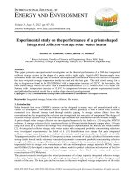
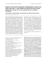
One battery 4 designed specifically for electric vehi-
cles uses multiple lug, horizontal plates and is shown in
Fig. 1. The module shown in the figure has three cells with
each cell consisting of a horizontal stack of double-lugged
plates separated by glass-mat separators. The horizontal
configuration allows the use of a multiple lugged conduc-
tor structure in order to achieve high specific power. This
design feature effectively reduces grid resistance by short-
ening conductor lengths. The horizontal configuration also
allows the use of mechanical containment where axial
pressure is applied to the face of the positive electrode.
wx
Mechanical containment has been shown 5–8 to dramati-
cally improve the life of lead–acid batteries. Cells were
wx
fabricated according to the design 4 shown in Fig. 1 and
Ž
tested. The cells attained approximately 600 cycles 80%
.
depth of discharge, DOD, at the 2-h rate and had not
failed before the tests were stopped. The projected specific
Ž.
energy for these cells operated at 1108F438C was 35 W
Ž.
hrkg 2-h rate . The specific power was measured to be
Ž.
approximately 200 Wrkg 80% DOD .
In this paper, we will modify the design previously
wx
presented 4 so as to improve its use in an electric vehicle
Ž.
or a range extended, hybrid electric vehicle REHEV . A
REHEV operates mostly as an electric vehicle but uses a
0378-7753r00r$ - see front matter q 2000 Elsevier Science S.A. All rights reserved.
Ž.
PII: S0378-7753 99 00392-4
()
T.C. Dayton, D.B. Edwardsr Journal of Power Sources 85 2000 137–144138
Fig. 1. Sealed, lead–acid battery module.
small heat engine and alternator to charge its batteries
during long trips. The battery requirements for these two
vehicles are similar because both vehicles have significant
electric vehicle range and need a high specific energy. The
REHEV battery will not be as large as the electric vehicle
battery and so will need to deliver more power per weight
than the equivalent electric vehicle battery. However, the
battery requirements for these two vehicles are similar so
that a generic battery can be designed for both vehicle
types.
wx
In a previous paper 9 , the design shown in Fig. 1 was
modified for use in a parallel hybrid electric vehicle where
the battery acts to load level the heat engine. The modified
design was projected to achieve a specific energy of 22 W
hrkg at a specific power of 550 Wrkg. At a reduced
power of 31.8 Wrkg, the battery was projected to have a
specific energy of 31.6 W hrkg and an energy density of
92.3 W hrl. Additives, in the form of glass microspheres,
were added to the paste to achieve this performance.
However, in this design the specific energy was reduced in
order to increase the specific power. We realized that we
could have improved the specific energy much more if we
had not needed to meet the high specific power require-
ments and this knowledge encouraged us to write this
paper.
In this paper, we will investigate the use of paste
additives in battery designs and determine how they can
improve the performance of sealed, lead–acid batteries in
REHEV and electric vehicles. We will use the design
wx
reported in Ref. 4 as the baseline design. We will design
batteries having different additives including glass micro-
spheres, porous glass microspheres, and metal-coated,
porous glass microspheres. The designs will show how the
performance can be progressively improved with the use
of additives. We will employ models previously developed
wx
10–14 to estimate this performance improvement. We
will show how, with a realistic development program, the
lead–acid battery can meet the performance requirements
for these vehicles.
In Section 2, we will discuss the models used to
estimate the performance of the designs developed in this
paper. We will document the models by comparing their
results with the test results of the baseline design. In
subsequent sections, we will design batteries having differ-
ent additives and estimate their performance with our
models. After we have evaluated the design, we will
discuss the results. Section 9 will summarize and give our
conclusions.
2. Models
In an attempt to better understand lead–acid batteries
and the physical processes that limit capacity, computer
models were developed that simulate the conductivity of
the positive active material and the diffusion of sulfate
wx
ions. Researchers 15,16 have found that after a certain
amount of the active material has reacted the remaining
material becomes isolated and cannot react. The amount of
active material that can be discharged before the remaining
material becomes isolated is termed the critical volume
fraction. Values for the critical volume fraction have been
estimated to be approximately 60–70% for homogeneous
paste. A model has been developed, called the conductivity
model, that estimates the critical volume fraction of paste
wx
containing non-conducting or conducting additives 10 .
In order to model the conductivity of the active mate-
rial, the material is assumed to be made of spherical
particles and modeled as nodes on a two-dimensional grid.
Each node is connected to the surrounding eight nodes by
a conductive pathway. The grid contains over one million
nodes, 1024= 1024 nodes. The model randomly chooses a
node and attempts to find a conductive pathway to the
edge of the grid. If a pathway can be found, the starting
node is considered discharged and marked as non-conduc-
tive. If a pathway is not found, the starting node is marked
as isolated. After all nodes have been selected and path-
ways have been tried, the model reports the number of
nodes that were either discharged or isolated. The critical
volume fraction is calculated as the ratio of discharged
nodes to the initial number of available nodes.
The model can take into account any non-conductive
additives by initially marking those nodes as discharged.
For conductive additives the model marks those nodes as
always conductive. The amounts of additives are given as
volume percentages and the size of the individual additive
is given relative to the base node size. For example, a
non-conductive glass microsphere, approximately 20–50
mm in diameter, is represented as a particle of 10= 10
wx
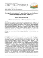
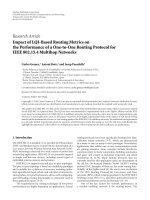
nodes. Using this model, Fig. 2 14 was created to show
the effect on the critical volume fraction of adding conduc-
tive and non-conductive additives.
The second model, called the diffusion model, uses
finite difference equations and Fick’s law to estimate the
acid concentration in both the negative and positive mate-
rial as well as between them as a function of time. The
Nernst equation is then used to determine the battery
potential. The model combines diffusion and conductivity
parameters, including the critical volume fraction from the
()
T.C. Dayton, D.B. Edwardsr Journal of Power Sources 85 2000 137–144 139
Fig. 2. Critical volume fraction with material additives.
conductivity model, to estimate lead–acid battery perfor-
mance over a wide range of discharge rates. The model
produces voltage vs. time curves, percent material reaction
curves, and acid concentration plots. The model is helpful
in understanding the behavior of lead–acid batteries and
can be used to develop new cell designs. Once the plate
and cell parameters are established, the model can predict
the cell’s performance and allows for iterations to deter-
mine optimum parameter values.
3. Electric vehicle requirements
In order to develop a good battery design, we must first
understand how it will be used. We will establish the
power requirements for the battery from a previously
wx
reported electric vehicle design 17 for a lead–acid bat-
tery. This electric vehicle can be characterized by a few
critical parameters which define the road load. The road
load equation determines the battery power required to
maintain the vehicle at a given speed and is given as:
11
3
PVs
r
CAVq
m
MgV
Ž.
BAD
ž/
hh
2
GM
where
r
s1.2929 kgrm
3
, gs 9.8 mrs
2
, V is the veloc-
A
ity in mrs and the other parameters are given in Table 1.
Table 1
Electric vehicle parameters
Parameter Value
Ž.
Motor to wheel gear efficiency
h
0.95
G
Ž.
Motor efficiency
h
0.90
M
Ž.
Drag coefficient C 0.32
D
2
Ž.
Frontal area A 1.88 m
Rolling resistance
m
0.009
Ž.
Total vehicle weight M 1606 kg
Battery weight 600 kg
Table 2
Battery design parameters
Parameters Values
Positive plate
Ž.
Grid thickness 0.071 in. 0.18 cm
3
Grid volume 3.2 cm
Grid weight 35 g
Ž.
Plate thickness 0.076 in. 0.19 cm
Paste weight 69 g
Critical volume fraction 60%
Number positive plates 14
Negative Plate
Ž.
Grid thickness 0.060 in. 0.15 cm
3
Grid volume 2.7 cm
Grid weight 30 g
Ž.
Plate thickness 0.067 in. 0.17 cm
Paste weight 57.3 g
Critical volume fraction 65%
Number negative plates 15
Ž.
Effective distance between plates 0.0572 in. 0.145 cm
3
Electrolyte volume 765 cm
3
Electrolyte specific gravity 1.3 grcm
Electrolyte initial concentration 5.1 molsrl
Ž.
Misc. weights terminals, straps, etc. 246 g
Case weight 246 g
Total weight 4.253 kg
Using the vehicle parameters and the road load equa-
tion, the power required of the batteries at a speed of 55
Ž.
milesrh 24.6 mrs is 10.8 kW. For the battery pack
weight of 600 kg, the specific power is 18 Wrkg. At a
Ž.
speed of 70 milesrh 31.3 mrs , the battery power re-
quired is 19 kW and the specific power is 31.7 Wrkg.
With these power requirements, the effectiveness of a
battery design powering an electric vehicle can be estab-
lished.
This vehicle design has been considerably improved
upon by the General Motors Impact electric vehicle intro-
duced in 1992. With its improved aerodynamics and low
rolling resistance tires it has an approximate road load of
5.5 kW at 55 milesrh and 9.5 kW at 70 milesrh. With its
500-kg battery pack, the Impact requires a specific power
of 11 and 19 Wrkg for speeds of 55 and 70 milesrh,
respectively.
4. Baseline battery
The baseline battery for this research was developed at
Ž.
the Jet Propulsion Laboratory JPL to be used in an
electric vehicle application. The design consists of horizon-
Table 3
Baseline battery design test results
Test parameter Average results
Energy discharged 150 W h
Specific energy 35.4 W hrkg
()
T.C. Dayton, D.B. Edwardsr Journal of Power Sources 85 2000 137–144140
Table 4
Model results of baseline battery design
Discharge Time Discharge Utilization
Ž. Ž. Ž . Ž.
rate A s Ah %
2.70 7198 5.40 34.91
5.00 3633 5.05 32.63
tally oriented, dual lugged plates in a sealed configuration
wx
4 . Table 2 shows the design parameters for this battery.
This battery was built and tested by personnel at JPL.
Using these parameters, the baseline battery design was
modeled and the cell discharge was simulated. Table 3
gives the performance of this battery at a discharge rate of
18 Wrkg, approximately the 2-h rate. The model predicts
a discharge energy of 150 W h and a specific energy of
35.4 W hrkg at the 2-h rate. Table 4 gives the utilization
of the positive active material predicted by the model
when the baseline cell is discharged at the 18 and 32
Wrkg rates. The specific power of 32 Wrkg corresponds
to a discharge rate close to the 1-h rate. A discharge
energy of 142 W h and a specific energy of 33.5 W hrkg
Ž.
were predicted by the model at the 1-h rate see Table 5 .
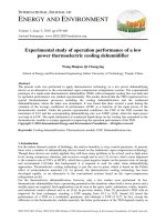
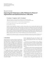
Fig. 3 shows the profiles of the reacted material every
2000 s for the 2-h discharge rate. The active material is
reacted up to the critical volume fraction at the edge of
both the negative and positive plates. A portion of the
interior active material also reacts. The overall utilization
is given in Table 4 as approximately 35%. Comparison of
the 2-h rate discharge with those reported by JPL suggest
that the model can accurately predict the performance of
this cell design. The rest of this paper assumes that the
accuracy of the model continues through several iterative
cell designs. The performance predicted by the model will
be the basis for determining the effectiveness of cell
designs with additives.
Ž.
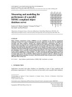
Fig. 4 shows a plot of specific energy W hrkg versus
Ž.
specific power Wrkg . This figure shows the 1- and 2-h
discharge rates as reference lines of specific power. The
Ž.
2-h discharge rate 18 Wrkg for this battery design
corresponds with the road load for a typical electric vehi-
cle traveling at 55 milesrh. Likewise, the 1-h discharge
Ž.
rate 32 Wrkg represents an electric vehicle speed of 70
milesrh. Therefore, the baseline battery design would be
able to power an electric vehicle 2 h at a speed of 55
milesrh, for a maximum range of 110 miles. Alterna-
tively, the electric vehicle could be powered for 1 h at a
speed of 70 milesrh, for a maximum range of 70 miles.
The model results for this design, and the results for all
subsequent designs, will be used to predict cell perfor-
mance at the specific powers of 18 and 32 Wrkg. Using
these specific powers, we can compare the results of the
computer simulations for different designs and establish
the effectiveness of the designs for EVs and REHEVs. In
the following sections, we investigate using different paste
additives in the horizontal battery design and compare
these designs using specific energy versus specific power
plots.
5. Design with glass microspheres
As shown in Table 4, only 35% of the active material in
the positive plate of the baseline battery is reacting. It
would be weight effective to remove the portions that do
not react. Non-conducive glass microspheres can be added
to the positive material as a filler to replace material that is
not reacting. These microspheres are approximately 10
times larger than the lead oxide particles and have a
density approximately 20 times less. If 30% by volume of
Ž.
large additives 10= 10 are added to the positive active
material, the critical volume fraction is reduced from 60%
to 55%, as shown in Fig. 2. It is assumed that the additives
will displace lead oxide material and not occupy any of the
pore volume. Therefore, the 30% by volume number is
with respect to the volume of the lead oxide particles. This
Table 5
Results of model with additive types at specific powers of 18 and 32 Wrkg
Additive type Specific power Energy Increase Specific energy Increase
Ž. Ž. Ž. Ž . Ž.
Wrkg W h % W hrkg %
None 18 151.0 – 35.5 –
32 142.0 – 33.5 –
30% Microspheres 18 155.0 2.6 47.0 32.4
32 145.0 2.1 44.0 31.3
23% Porous, microspheres 18 182.5 20.9 50.0 40.8
32 171.5 20.8 47.0 40.3
30% Conductive, porous, microspheres 18 195.0 29.1 56.0 57.8
32 184.0 29.6 53.0 58.2
20% Small, conductiveq10% porous, microspheres 18 206.0 36.4 63.0 77.5
32 196.0 38.0 60.0 79.1
30% Small, conductive, porous, microspheres 18 216.5 43.4 68.5 93.0
32 207.0 45.8 65.5 95.5
()
T.C. Dayton, D.B. Edwardsr Journal of Power Sources 85 2000 137–144 141
Fig. 3. Profiles of reacted material every 2000 s of baseline battery at 2-h discharge rate.
assumption holds for all the battery designs presented in
this paper. With the addition of the additives, the positive
Ž.
active material PAM weight is reduced 30% from 69 to
48.3 g. To keep the battery design consistent, the negative
Ž.
active material NAM weight, grid volumes and weights,
misc. weights and case weights are also reduced by 30%.
The electrolyte volume and weight is not reduced since the
PAM and NAM volumes on the plates did not change. The
addition of the glass microspheres increases the total cell
weight by only 1%. Due to the reduction in PAM weight
for each individual plate, the corresponding cell needs an
additional six plate pairs.
For this design, the energy discharged at specific pow-
ers of 18 and 32 Wrkg is 155 and 145 W h, respectively.
This increase in discharged energy is due to the increase in
utilization of the positive active material, as listed in Table
5. Fig. 5 shows the profiles of reacted material every 2000
s for the specific power of 18 Wrkg. Even though the
critical volume fraction has been reduced, the overall
utilization has increased since more interior material can
react. Fig. 7 shows that at a specific power of 18 and 32
Wrkg the specific energy increases to 47 and 44 W hrkg,
respectively. Table 5 summarizes the model results and
shows that by adding non-conducting additives the specific
Fig. 4. W hrkg versus Wrkg for baseline cell design.
()
T.C. Dayton, D.B. Edwardsr Journal of Power Sources 85 2000 137–144142
Fig. 5. Profiles of reacted material every 2000 s of design with glass microspheres at 18 Wrkg.
energy increased 31–32% to a specific energy of approxi-
mately 45 W hrkg. This increase is due to the 22.3%
reduction in plate weight and a 16% increase in utilization.
6. Design with porous, glass microspheres
In the next iteration on this battery design, we used
porous glass microsphere additives in the positive material.
The glass microspheres are 90% hollow, so by simply
making holes in the microspheres, a porosity of 90% can
be achieved. The reason for considering a porous additive
is that the porosity of the active material can be increased
since the additive can be used as electrolyte storage within
the active material. If 23% by volume of porous, glass
microspheres are added to the positive and negative active
material, the porosity of the positive active material in-
creases from 45% to 65% and the porosity of the negative
active material increases from 50% to 70%. The critical
volume fraction is 57% and 62% for the positive and
negative active material, respectively. The electrolyte stored
in the porous additives in the active material does increase
the cell weight. Energy discharged at specific powers of 18
and 32 Wrkg increase to 182.5 and 171.5 W h and the
specific energies increase to 50 and 47 W hrkg, as shown
in Fig. 7. Table 5 indicates that this represents a 40%
Fig. 6. Profiles of reacted material every 2000 s of design with 23% porous microspheres at 18 Wrkg.
()
T.C. Dayton, D.B. Edwardsr Journal of Power Sources 85 2000 137–144 143
Ž. Ž.
Fig. 7. Specific energy W hrkg versus specific power Wrkg for all cell models.
increase in specific energy over the baseline battery de-
sign.
Fig. 6 gives the profiles of the reacted material every
2000 s for the specific power of 18 Wrkg. The figure
shows that for this cell design the critical volume fraction
in the positive active material of 57% has nearly been
reached at this discharge rate. Therefore, this design has
reached the point where conductivity is limiting the perfor-
mance. If more glass microspheres were added to the
active material there would be no further increase in
performance. In order to further increase the battery per-
formance, conductive additives will be needed to raise the
critical volume fraction of the active material.
7. Design with conductive, porous, glass microspheres
In the next iterative design step, we used conductive,
porous glass microspheres to increase the conductivity and
the critical volume fraction of the active material. Assum-
ing the porous, glass microspheres can be coated with a
conductive coating, the conductivity model predicts that
the critical volume fraction increases by 12% with a 30%
Ž.
addition of large 10= 10 conductive additives, as shown
in Fig. 2. The critical volume fraction for the PAM and
NAM increases to 67% and 72%, respectively. With this
change the model predicts an energy discharge of 195 and
184 W h and a specific energy of 56 and 53 W hrkg for
specific powers of 18 and 32 Wrkg, respectively.
Fig. 7 shows how the specific energy of this design
compares with the other designs. Table 5 gives values for
the energy discharged and specific energy of this design.
The performance of the design is limited by the critical
volume fraction of the active material. According to Fig. 2,
a higher increase in the critical volume fraction can be
accomplished by using smaller, conductive additives.
8. Designs with smaller, conductive, porous, glass mi-
crospheres
As shown in Fig. 2, when 20% by volume of small
Ž.
additives 1= 1 are included in the active material the
critical volume fraction increases to 75%. If 10% by
Ž.
volume of large microspheres ) 10= 10 are also added
the critical volume fraction does not decrease significantly.
If both the conductive additive and the large microspheres
are considered porous, the net results are added paste
Ž. Ž.
porosity 27% and increased conductivity 15% . To pro-
vide the needed electrolyte, the active material thickness in
both the negative and positive plates are reduced by 7%.
This distance between grids remains the same, thus the
volume between plates has increased so more electrolyte
may be added. For the specific powers of 18 and 32
Wrkg, the resulting energy discharges are 206 and 196 W
h with specific energies of 63 and 60 W hrkg. This cell
design is limited by the conductivity of the active material.
Ž.
When 30% by volume of small additives 1= 1 are
included in the active material the critical volume fraction
increases to 85%, as shown in Fig. 2. If these small
additives are again considered porous we then have added
Ž. Ž.
porosity 27% and increased conductivity 25% . To pro-
vide the needed electrolyte, the active material thickness in
both the negative and positive plates are reduced an addi-
tional 8%. For the specific powers of 18 and 32 Wrkg, the
resulting energy discharges are 216.5 and 207 W h with
specific energies of 68.5 and 65.5 W hrkg. This cell
design is also limited by the conductivity of the active
material but since we are currently reacting 85% of the
()
T.C. Dayton, D.B. Edwardsr Journal of Power Sources 85 2000 137–144144
positive active material, it is unlikely we can realistically
increase the critical volume fraction any higher.
Fig. 7 shows how the specific energy has been in-
creased with the use of small conductive additives in these
two models. At specific powers of 18 and 32 Wrkg the
specific energies are nearly double the baseline battery
design and the discharge times have increased by a factor
of 2.5.
9. Conclusions
The baseline, horizontal plate battery containing no
additives has a specific energy of 30–35 W hrkg. This
battery is designed to have a high specific power to meet
the demands of electric and hybrid electric vehicles. This
paper has demonstrated, through a series of battery designs
having different paste additives, that the specific energy
performance can be significantly improved. With the addi-
tion of 30% by volume of conductive, porous, glass micro-
spheres in the negative and positive active materials the
specific energy can be increased by 58% to an estimated
50–60Whrkg. If smaller additive sizes are considered,
the specific energy can be increased 95% to an estimated
60–70 W hrkg.
By increasing the specific energy of the baseline battery
design the feasibility of using lead–acid batteries in elec-
tric and hybrid electric vehicles increases. When the dis-
charge times are examined, the final cell design discharged
at the original 1- and 2-h rates would have discharge times
nearly double the baseline. This means that for the same
battery size and weight, the new cell design would almost
double the range of present electric or hybrid electric
vehicles.
We realize that these projections are based on theoreti-
cal models and that much work needs to be performed in
order to validate these designs. However, we believe the
strategy provided in this paper could lead to a substantially
improved high power, lead–acid battery.
References
wx
1 K. Hardy et al., Advanced Vehicle System Assessment, JPL D-230,
Jet Propulsion Laboratory, Pasadena, CA, 1983.
wx
2 G.L. Henriksen, D.L. Douglas, C.J. Warde, National Program Plan
for Electric Vehicle Battery Research and Development, DOErID-
10219, 1989.
wx
3 E.Z. Ratner, P.C. Symons, W. Walsh, C.J. Warde, Assessment of
Battery Technologies for Electric Vehicles, DOErID-10243, 1989.
wx
4 D.B. Edwards, B. Carter, A high power, sealed, lead–acid battery
Ž.
for electric vehicles, J. Eng. Ind. 112 1990 293–298.
wx Ž.
5 J. Alzieu, J. Robert, J. Power Sources 13 1984 93–100.
wx Ž.
6 J. Alzieu, N. Koechlin, J. Robert, J. Electrochem. Soc., 1987
1881–1884.
wx
7 K. Takahashi, M. Tsubota, K. Yonezu, K. Ando, J. Electrochem.
Ž.
Soc. 130 1983 2144–2149.
wx Ž.
8 J. Landfors, J. Power Sources 30 1990 131–141.
wx
9 D.B. Edwards, R.L. Cantrell, T. Dayton, Predicting the Performance
of Batteries Having Paste Additives, The Twelfth Annual Battery
Conference, IEEE 97th 8226, California State University, Long
Beach, CA, 1997.
wx
10 D.B. Edwardsm, P.W. Appel, Conductivity model for lead–acid
battery electrodes discharged at low rates, J. Power Sources 38
Ž.
1992 218–286.
wx
11 P.W. Appel, D.B. Edwards, T. Stalick, Modeling the effects of
electrolyte diffusion and paste conductivity on lead–acid battery
Ž.
performance, J. Power Sources 46 1993 49–60.
wx
12 D.B. Edwards, P.W. Appel, Modeling lead–acid batteries that have
positive electrodes containing hollow, glass microspheres, J. Power
Ž.
Sources 46 1993 39–48.
wx
13 R.L. Cantrell, D.B. Edwards, P.S. Gill, Predicting lead–acid battery
electrode performance using finite difference equations, J. Power
Ž.
Sources 73 1998 204–215.
wx
14 P.W. Appel, D.B. Edwards, Understanding and defeating the physi-
cal mechanisms limiting the capacity of lead–acid batteries, Adv.
Ž.
Perform. Mater. 3 1996 43–45.
wx
15 H. Metzendor, The capacity limiting role of the electronic conductiv-
ity of the active material in lead–acid batteries during discharge, J.
Ž.
Power Sources 7 1982 281–291.
wx
16 J.P. Pohl, W. Schendler, The electronic conductivity of compact lead
dioxide samples with various stoichiometric compositions, J. Power
Ž.
Sources 6 1981 245–250.
wx
17 D.B. Edwards, An Electric Vehicle Design Based on a High-Power,
Sealed, Lead–Acid Battery, SAE Technical Paper Series, 881790,
1988.