The role of carbon in valve-regulated lead–acid battery technology potx
Bạn đang xem bản rút gọn của tài liệu. Xem và tải ngay bản đầy đủ của tài liệu tại đây (230.05 KB, 8 trang )
Journal of Power Sources 157 (2006) 3–10
Review
The role of carbon in valve-regulated lead–acid battery technology
ଝ
P.T. Moseley
a,∗
, R.F. Nelson
b
, A.F. Hollenkamp
c
a
International Lead Zinc Research Organization, 2525, Meridian Parkway, Research Triangle Park, North Carolina, NC 27709, USA
b
Recombination Technologies LLC, 909 Santa Fe Drive, Denver, Colorado, CO 80204, USA
c
CSIRO Energy Technology, Box 312, Clayton South, Vic. 3169, Australia
Available online 29 March 2006
Abstract
The properties of different forms of carbon and their potential, as active mass additives, for influencing the performance of valve-regulated
lead–acid batteries are reviewed. Carbon additives to the positive active-mass appear to benefit capacity, but are progressively lost due to oxidation.
Some forms of carbon in the negative active-material are able to resist the tendency to sulfation during high-rate partial-state-of-charge operation
to some considerable extent, but the mechanism of this benefit is not yet fully understood.
© 2006 Elsevier B.V. All rights reserved.
Keywords: Valve-regulated lead–acid; Batteries; Carbon; Capacity; Power; Cycle-life
Contents
1. Introduction 3
2. Allotropes of carbon and their properties 3
3. Conventional use of carbon in lead–acid batteries 5
4. Effects of carbon on the behaviour of the positive plate 5
5. Increased levels of carbon in the negative plate 6
6. Asymmetric electrochemical capacitors 8
7. Conclusions and ultimate prospects 9
References 9
1. Introduction
For many years, carbon has been favoured as an additive to the
negative active-material in lead–acid batteries, despite the fact
that there has never been universal agreement on the reasons for
its use [1]. Now that the valve-regulated version of the battery
(VRLA) is being exposed to high-rate partial-state-of-charge
(HRPSoC) operation in various applications [2], evidence is
ଝ
This review is one of a series dealing with the role of carbon in electro-
chemical energy storage. The review covering carbon properties and their role
in supercapacitors is also published in this issue, J. Power Sources, volume 157,
issue 1, pages 11–27. The reviews covering the role of carbon in fuel cells and
the role of carbon in graphite and carbon powders were published in J. Power
Sources, volume 156, issue 2, pages 128–150.
∗
Corresponding author. Tel.: +1 919 361 4647; fax: +1 919 361 1957.
E-mail addresses: (P.T. Moseley),
(R.F. Nelson),
(A.F. Hollenkamp).
emerging that demonstrates clearly the beneficial effects of car-
bon. In particular, increased levels of certain forms of carbon
act to restrict the progress of plate sulfation, the process which
ultimately terminates the useful life of the battery in HRPSoC
duty. There has also been a report [3] that the addition of cer-
tain types of carbon to the positive active-material can improve
battery capacity and life. In view of these developments, and
the diverse range of chemical and physical properties that are
observed in different forms of carbon, it is timely to review the
mechanisms by whichcarbon additions could benefit VRLAbat-
teries in various duty cycles, and to assess the forms of carbon
that are likely to provide the greatest benefit.
2. Allotropes of carbon and their properties
Elemental carbon participates in two distinct types of cova-
lent bonding. In the diamond structure, each atom is joined to
0378-7753/$ – see front matter © 2006 Elsevier B.V. All rights reserved.
doi:10.1016/j.jpowsour.2006.02.031
4 P.T. Moseley et al. / Journal of Power Sources 157 (2006) 3–10
four neighbours, at a distance of 1.54
˚
A, by tetrahedrally ori-
ented bonds that are formed by sp
3
hybrid orbitals. There is an
energy gap of 5.3 eV between the and
*
bands so that the
material is an insulator [4]. In the graphite structure, the atoms
are arranged in planar hexagonal networks (so-called ‘graphene’
layers) that are held together by strong sp
2
bonds, 1.42
˚
Ain
length. The bonding between these planar layers (van der Waals
type) is relatively weak (bond length 3.35
˚
A). In graphite, which
is the equilibrium phase under ambient conditions, and
*
bands around the Fermi level fill the –
*
gap, which renders
the material semi-metallic. The structure leaves the conductiv-
ity highly anisotropic, however, with the in-plane conductivity
two-to-three orders of magnitude greater than that in the direc-
tion perpendicular to the plane [5]. More recently discovered
forms of carbon (fullerenes, nanotubes, etc.) consist of struc-
tures in which hexagonal networks of carbon atoms are curved
into spherical or cylindrical shapes.
The diamond structure tends to exhibit a high degree of crys-
talline perfection, although isolated point defects can occur. The
layered structure in graphite, however, allows a range of defect
opportunities, that give rise to considerable variability in phys-
ical properties. The normal –AB– layer stacking sequence, in
which the atoms of alternate layers in the crystallographic c-
axis sequence are situated identically in the x–y plane, results in a
hexagonal structure. The structure can,however, be re-ordered to
construct a rhombohedral sequence –ABC– in which the atoms
of every third layer in the c axis sequence are situated identically
in the x–y plane. Such re-ordering can be partial or complete.
Further, a fraction of the carbon atoms can be sp
3
rather than
sp
2
hybridized, with the result that the graphene layers become
buckled. Indeed, the concentration of sp
3
carbons can be quite
high [4]. Disordered carbon systems with the same sp
2
/sp
3
ratio
show a variety of different electronic structures owing to the
degree of clustering of sp
2
carbons into ‘graphitic domains’ [6].
A disordered distribution of sp
2
sites in an sp
2
/sp
3
mixed sys-
tem disrupts the conjugated electron system even when the
concentration of sp
3
carbons is rather low. This ‘non-graphitic’
disorder serves to reduce conductivity, but this can be restored by
thermally induced migration of sp
3
defects at temperatures from
200 to 400
◦
C [4]. The degree of crystalline perfection is reduced
to a minimum in the production of amorphous or glassy forms
of carbon. The ultimate crystallite size for carbon materials can
vary over a large range, from 0.001 to 100 m [7]. Evidently,
the specific surface area of such material can also vary widely.
Departures from the perfect structure of graphite, which can
arise from the occurrence of stacking faults and/or the accom-
modation of sp
3
carbon atoms, cause the conductance of the
material to be variable over a wide range [4]. The chemical reac-
tivity of a given carbon material is influenced by the specific area
and the composition of the surface. Each sp
3
carbon atom has
one free bond that is not involved in holding the graphene layer
together. Such bonds can accommodate a variety of chemical
entities, e.g., carbonyl, carboxyl, lactone, quinone, phenol, and
various sulfur and nitrogen species [7].
Two important factors affect the electrochemical behaviour
of graphite, namely, the layered structure and an amphoteric dis-
position [8]. The layered structure of graphite, which involves
strong bonds within the sheets of atoms lying perpendicular
to the c axis and weak bonds between the sheets, allows a
rich intercalation chemistry. A wide variety of species can be
inserted between the graphene sheets and this increases the spac-
ing between the sheets (Fig. 1) without disturbing the bonds that
hold the sheets together. The earliest graphite intercalation com-
pounds, which involved the incorporation of potassium, were
reported over 160 years ago [9]. Intercalation into graphite host
materials is classified in terms of ‘n’ stages. Stage-n is defined as
the structure in which intercalates are accommodated regularly
in every nth graphitic gallery. The structure in which intercalates
occupy every graphite gallery is termed a stage-1 structure (as
in Fig. 1). The process of intercalation can give rise to a large
expansion in the c axis direction of the crystal structure as quite
large ions and/or groups can be accommodated.
The amphoteric characteristic arises because graphite is a
semi-metal (the valence and conduction bands overlap slightly
[10]) in which both electrons and holes are always available to
carry current. As a result, graphite can act as an oxidant towards
an electron donor intercalate and as a reductant towards electron
acceptor species such as acids. Pure graphite intercalation com-
pounds can be synthesized with stages between 1 and, at least
12, depending on the nature of the intercalate and the synthesis
route. Graphite intercalation compounds can exhibit remarkable
properties. For example, the stage-1 lithium graphite intercala-
Fig. 1. Schematic of graphite intercalation. (a) An ‘edge-on’ view of the graphene planes in un-reacted graphite; (b) an edge-on view of a stage-1 graphite intercalation
compound showing expansion of the interplanar spacing to accommodate the guest species. The dimension, x, can take values up to 9
˚
A or more without disrupting
the long-range order of the crystal structure.
P.T. Moseley et al. / Journal of Power Sources 157 (2006) 3–10 5
Table 1
Conductivity in a and c axial directions of graphite and some graphite intercalation compounds (GICs)
Material Formal charge on carbon Conductivity, a-axis (S cm
−1
) Conductivity, c-axis (S cm
−1
) Reference
Graphite 0 1 × 10
4
to 2.5 × 10
4
10
2
[15,16]
Bisulfate GIC + ∼1.6 × 10
5
∼2 × 10
2
[17]
Lithium GIC − 2.4 × 10
5
1.8 × 10
4
[11]
tion compound has a conductivity of 2.4 × 10
5
Scm
−1
within
the graphene planes and 1.8 × 10
4
Scm
−1
in the direction per-
pendicular to the planes [11].
Graphite forms a number of intercalation compounds with
sulfuric acid [12–14]. These develop when the intercalation pro-
cess is assisted either by the presence of an oxidizing agent
(such as PbO
2
) or electrochemically when the material is held
at a positive potential. In general, the process involves the inser-
tion of both HSO
4
−
ions and neutral H
2
SO
4
molecules, with
the charge on the former balanced by a positive charge on the
oxidized graphite network (e.g. C
24
+
·HSO
4
−
·2.5H
2
SO
4
). The
stage-1 sulfuric acid graphite intercalation compound can be
prepared in 96% acid at a cell voltage just below the decompo-
sition potential of the electrolyte [8]. At any particular oxidation
level, the graphite bisulfate compound can be decomposed by a
cathodic current.
The conductivities of graphite and of some graphite inter-
calation compounds, in the a and c axial directions, are shown
in Table 1. The data show that formation of the intercalation
compounds generally results in an increase in electronic con-
ductivity.
It has recently been reported [18,19] that hydrogen can be
stored in carbon single-wall nanotubes by an electrochemical
process. Carbon samples subjected to a negative potential in a
cell with potassium hydroxide electrolyte and a nickel counter
electrode were found to take up 1–2 wt.% of hydrogen that could
be released when the potential was reversed. Further, the maxi-
mum stored concentration could be increased by incorporating
Group I metals (especially, lithium) into the carbon structure
[19]. It is not yet clear whether this result signals the feasibility
of protonic intercalation into the graphite structure, but it has
been suggested [20] that there is nothing special about carbon
nanomaterials (as opposed to other forms of carbon) as far as
hydrogen uptake is concerned. Indeed, Frackowiak and B
´
eguin
[21] have shown that electrodes constructed from high surface-
area carbon fabrics (woven bundles of activated carbon fibre)
are able to store reversibly between 1.5 and 2.0 wt.% hydro-
gen. These authors suggested that the mechanism of storage
was intercalation (of nascent hydrogen) into graphitic domains,
rather than trapping of hydrogen by carbon-surface functional
groups. It would clearly be valuable to establish whether or
not hydrogen intercalation into graphite does occur and, if so,
whether the process mightenhance the electronic conductivity of
the graphite in the same way as does the intercalation of lithium.
3. Conventional use of carbon in lead–acid batteries
Three materials are usually added, as minor components, to
the negative paste mix of lead–acid batteries, namely, carbon
black (an amorphous form with a particle size in the range
0.01–0.4 m, usually present at 0.15–0.25 wt.%), an organic
material (usually a lignosulfonate, at 0.2–0.4 wt.%), and bar-
ium sulfate (0.3–0.5 wt.%). This mixture is often referred to as
an ‘expander’ since its purpose is, at least partly, to maintain
the active material on the plate in a high-surface-area form. The
amounts of each of the three additives have, to date, been kept
to a minimum, in order to displace the smallest amount of active
material possible. The understanding of the function of each
component of the expander is incomplete, however. It is gener-
ally agreed that the barium sulfate serves as a nucleating agent
for lead sulfate (with which it is isomorphous) during discharge.
The organic component is the actual expander as it acts as a dis-
persing agent, discouraging the increase of particle size and the
concomitant decrease in surface area. It was originally felt that
the primary function of the carbon black portion was to ‘clear the
negative plates during formation’ and improve low-temperature
performance [22]. This implies that even such a small amount of
carbon may have a positive, but small, impact on negative-plate
conductivity. More recent work (see Section 5) has established
that larger amounts of specific types of carbon powders, flakes
and fibres can have a significant effect on plate conductivity, par-
ticularly in the HRPSoC operation of hybrid electric vehicles.
4. Effects of carbon on the behaviour of the positive
plate
Despite concern that carbon in the positive plate of the
lead–acid battery would be prone to oxidation, there have been
a number of investigations of the behaviour of carbon materials
as additives to the positive active material (PAM). In view of the
wide diversity of properties exhibited by the different forms of
carbon (Section 2, above), it is to be expected that some forms
are more stable in hostile environments than are others.
In 1987, it was reported [23] that the incorporation of
0.1–2.0 wt.% of graphite (99.6% purity) into the positive active-
material (PAM) of a lead–acid cell improved both the discharge
capacity and the cycle-life. The study provided X-ray diffraction
evidence of the generation of the bisulfate graphite intercalation
compound during cell formation and it was suggested that the
intercalation process (which may be reversible during discharge)
might enhance the porosity and, hence, the access of acid to the
PAM. The presence of the graphite certainly appeared to ren-
der the distribution of PbSO
4
discharge product more uniform
throughout the plate thickness. Interestingly, however, the bene-
ficial effect on discharge capacity was reported to increase with
graphite particle size, which appears to be the reverse of the
effect of carbon size in the negative plate (see below).
6 P.T. Moseley et al. / Journal of Power Sources 157 (2006) 3–10
An alternative (or perhaps additional) explanation of the
source of the benefit provided by the addition of graphite to
the PAM is that the irrigation of the plate by acid electrolyte
is assisted by electro-osmotic pumping [24]. Electro-osmosis is
the movement of liquid relative to a stationary charged surface
(e.g., a capillary or a porous plug) by an electric field. Graphite
present within the PAM is assumed to intercalate HSO
4
−
ions
and has been found [24] to exhibit a significant zeta poten-
tial. Zeta potential is the electric potential that exists across
the interface between a solid and a liquid. Since the material
in the cell is situated within an electric field (between plates of
different polarity), the conditions for liquid movement due to
electro-osmotic pumping may be satisfied [24]. Electro-osmotic
flow-rate is directly proportional to zeta potential. Further work
on the system would be necessary before this possibility could
be separated from the other possible processes by which the
presence of graphite might modify the performance of the elec-
trode.
Other work [25–27] investigated the addition of 0.2–1 wt.%
of carbon black to positive plates. It was found that at a level
of 0.2 wt.% carbon black improved the formation process, but
had little effect on cycle-life [27]. Roughly 60% of the car-
bon black was consumed during formation and the remainder
disappeared early in cycling. Interestingly, this carbon black
significantly increased the ␣/-PbO
2
ratio and the total PbO
2
created during formation compared with an equivalent paste
without carbon black. This unusual effect was attributed to a
combination of increased conductivity early in formation and a
resultant increase in PbO/␣-PbO
2
contact area, which resulted
in an enhanced level of direct conversion of PbO to ␣-PbO
2
.
Thus, the initial low-voltage stage of formation where ␣-PbO
2
is formed was extended [28]. Moreover, the morphology of the
PAM was uniform and largely composed of spherical agglom-
erates, which suggests that formation occurred with moderate,
uniform levels of supersaturation and at relatively low current
densities.
The addition of carbon fibres to the PAM has also been
reported [29] to increase both the capacity and cycle-life of test
batteries. This effect may also be due to an influence of the addi-
tive expanding porosity or it may be due to the fibres providing
mechanical support to the active mass [29].
Thus the evidence reported in the literature indicates that the
effect of adding carbon to the PAM on the capacity and life of a
lead–acid cell depends on the form of the carbon used. Carbon
black has little effect [27], but graphite [23] and carbon fibres
[29] are both beneficial.
5. Increased levels of carbon in the negative plate
The build-up of lead sulfate in the negative plate of a VRLA
cell operated under HRPSoC conditions represents a unique type
of behaviour not found when the cell is exposed to duty cycles
such as deep cycling from top-of-charge or float (standby) duty.
The phenomenon was first studied by scientists at Japan Storage
Battery Company (JSB) in their development of VRLA batter-
ies for HEV applications [30,31]. Their work focused mainly on
the benefits of employing higher concentrations of carbon black
to ameliorate the effect, a theme that is discussed later in this
section. Considerable detail on the characteristics of cell failure
under HRPSoC operation has been demonstrated in an extended
study by CSIRO, on 12-V 10-Ah VRLA batteries [32]. The
batteries were exposed to a simulated HEV duty that involved
cycling between 50% and 53% state-of-charge (SoC) at the 2C
rate. Cycling continued until the battery voltage reached pre-set
upper and lower limits at which point one ‘cycle-set’ had been
completed. Prior to commencing the next cycle-set, each battery
underwent a capacity-recovery process that involved repetitive
full discharge–charge cycles with substantial overcharge. Even
though the 2C rate is rather low compared with normal HEV
operation, the characteristic mode of degradation of the neg-
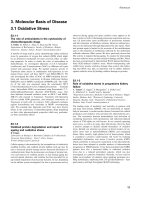
ative plate was rapidly demonstrated. Overall, as summarized
in Fig. 2, there was a progressive accumulation of lead sulfate.
This occurred throughout the course of the simulated HRPSoC
cycling, during which the nominal plate SoC was 50%. Impor-
tantly, the high levels of accumulated lead sulfate persisted into
the nominally fully charged state (recorded after the battery had
completed a recovery-charging sequence).
At the outset, the concentration of lead sulfate for the nomi-
nally 100% charged plates is low (∼5%), as expected (Fig. 2).
Discharging to 53% SoC (the starting point for the first set of
HEV cycles), sees the concentration rise by just over 15 wt.%,
in line with the expected utilization level. With the completion
of each successive cycle-set, however, the abundance of lead
sulfate increases markedly. By the end of the third cycle-set,
approximately half of the active material has been discharged to
lead sulfate, and the recharge process to a nominal 100% SoC
is clearly failing to reduce the sulfate level to any significant
degree. This accumulation of lead sulfate correlates well with
a progressive fall in both the time for which useful power is
available from the battery and the total capacity (at 2C) that is
available. By comparison, there is no equivalent increase in lead
sulfate content in the positive plates. In fact, the average concen-
trations, under both the 50% and 100% nominal SoC conditions,
Fig. 2. Abundance of lead sulfate on negative plate, as determined by chemical
analysis of total sulfur, plotted against length of simulated HEV service (see text
for details).
P.T. Moseley et al. / Journal of Power Sources 157 (2006) 3–10 7
decrease slightly from the initial values during the course of the
three cycle-sets [32]. This difference in behaviour between the
positive and negative plates, together with clear evidence that
appreciable hydrogen evolution develops during HEV cycling,
has led to the conclusion that failure of the negative plates under
HRPSoC duty is fundamentally due to poor charge-acceptance.
This process sets up conditions that ultimately accelerate the
further accumulation of lead sulfate and hasten the demise of
the cell.
As noted earlier, the first hint of a solution to the problem was
reported by the JSB group [30]. They showed that an increase in
the concentration of carbon black that is added to the negative
active-mass helps to resist the accumulation of lead sulfate on the
plate. Increases of three-times (3×) and ten-times (10×) the base
concentration (not reported) retarded the build-up of lead sulfate
in the negative plate and extended cycle-life. Specifically, the
increase in lead sulfate concentration per cycle fell from 0.1%
to 0.05% to 0.03% for the base, 3× and 10× carbon levels,
respectively [30].
A subsequent study [31] focused on the influence of car-
bon in negative plates at the same carbon levels adopted earlier
[30]. A most important observation was that at the 10× car-
bon level, the cycle-life was the best of the three and the lead
sulfate accumulation in the negative plates was lowest, com-
pared with the plates with lower carbon levels. Moreover, it was
found that while the 10× lead sulfate amount was lowest at the
end of cycling, the PbSO
4
crystal sizes were the largest. Nev-
ertheless, due to the relatively large amount of carbon present,
these large crystals were recharged easily. This suggests that
perhaps all lead–acid products, particularly those with long
shelf life or high deep-discharge cycle-life, might benefit greatly
from using increased levels of carbon in their negative paste
formulations.
The CSIRO team confirmed [32] that raising the concentra-
tion of a standard carbon black from 0.2% to 2.0 wt.% produces
an immediate gain in HEV cycle-life, although the negative
plates, in the case studied, still evolved hydrogen from quite
early in service. From conclusions reached in the earlier work
[30,31], it was thought that the beneficial effect of increased con-
centrations of carbon was due to a concomitant increase in the
conductivity of the negative active-mass. As shown by CSIRO,
conductivity does increase dramatically once the carbon content
is raised above a certain minimum threshold (Fig. 3). Conduc-
tivity alone was not responsible for the effect, however, because
different types of carbon, which gave similar improvements in
conductivity, conferred quite varied benefits on negative-plate
performance. Indeed, a series of tests with different types of car-
bon indicated [33] that the specific surface area (SSA) may be
more important, especially in the early stages of HEV service
(Fig. 4). In general, the best performance came from carbons
with the highest SSA which, because of this property, kept the
negative plate potential well out of the range in which hydro-
gen evolution would occur. Importantly, though, not all types of
carbon that suppressed negative plate potential conferred signif-
icantly better HRPSoC cycle-life performance [33].
During the early stages of HEV service the additive may
function simply as a second phase to keep the growing crystal-
Fig. 3. Relationship between conductivity and concentration of carbon black in
a specimen of a cured paste prepared from a mixture of carbon black (Raven
H
2
O Columbia Chemical Co., Marietta, GA, USA) and ␣-PbO. Increasing the
carbon black content from 0.2 to 2.0 wt.% results in an increase in conductivity
of about four orders of magnitude [32].
lites of PbSO
4
apart. The results summarized in Fig. 4 show a
high surface-area carbon material to be more effective than one
with low surface area. Indeed, it is possible that the second-phase
material does not have to be carbon in order to benefit the perfor-
mance of the negative plate. The incorporation of silica fibres has
been found [34] to improve charge-acceptance of the negative
plate. Such fibres are also reported to have a beneficial effect on
pasting, and thischaracteristic may be important since very high-
surface-area carbon is thought to have an opposite effect in that
it renders pasting more difficult. Much remains to be done in this
area, particularly if a composite additive might bring optimum
benefit, with one component providing the second phase func-
Fig. 4. Changes in negative-plate potential during simulated HEV service for
prototype cells containing different types and amounts of carbon materials in
their negative plates. Upper curves are for potentials measured at end of each
charging step; lower curves are for potentialsmeasured atend of each discharging
step. Two sets of curves for cells containing 0.4 wt.% carbon black with a very
high surface area (CB5, 1400 m
2
g
−1
) sustain their potentials far better than
curves for a cell containing 2 wt.% of carbon fibres with a low surface area
(CF1, 0.4 m
2
g
−1
) [33].
8 P.T. Moseley et al. / Journal of Power Sources 157 (2006) 3–10
tion to maintain electrolyte access between PbSO
4
crystallites
and another facilitating electronic access. In this connection, we
note that the dissolution–precipitation mechanism for recharge
of the active material requires a high-surface-area sulfate to assist
the dissolution step and good electronic access to assist the pre-
cipitation step (Pb
2+
+2e
−
→Pb).
Since carbon materials are known to exhibit a wide range of
structural disorder, to accommodate a variety of surface func-
tional groups and to have a rich intercalation chemistry, the
observation of a range of behaviour from different carbon addi-
tives in the negative plate is perhaps not surprising.
More recent work by Yuasa [35,36] has proposed the use
of conductive graphite fibres in the negative paste of batter-
ies intended for HRPSoC use in hybrid buses. With this and
other materials improvements, commercially available batteries
achieved HRPSoC lifetimes in excess of 300,000 cycles in the
laboratory which translates into a service life of some 4 years in
a hybrid electric bus.
In summary, there may be at least two ways in which car-
bon particles help to resist the accumulation of sulfate in the
negative plate during HRPSoC duty [32]: the first as a stable sec-
ond phase material separating individual crystallites of PbSO
4
and thus facilitating access of the electrolyte for the dissolution
stage of the recharge reaction, and the second as a facilitator
for extension of the electronically conducting surface available
for the precipitation of lead. These two functions might, in prin-
ciple, be performed by two different materials, for example a
high-surface-area silica for the first (some optimization may
be needed here since too fine a material may be ineffective,
or may degrade pasting properties, while too coarse a material
may require too great a material loading in order to achieve the
desired effect), and a highly conductive form of carbon for the
second.
6. Asymmetric electrochemical capacitors
Ultracapacitors based on non-Faradaic (double-layer charg-
ing) energy storage and delivery have severe drawbacks with
regard to high cost, low specific energy, and wide voltage swings.
Nevertheless, their high-power performance on both charge
and discharge makes them attractive for HRPSoC operation in
HEVs.
A variant of the traditional carbon–carbon ultracapacitor is
the so-called ‘asymmetric electrochemical capacitor’, or hybrid
energy storage (HES) device, examples of which have recently
been critically reviewed [37]. In such devices, a standard ultraca-
pacitor electrode comprising high-surface-area carbon is com-
bined with a modified battery electrode, together with an appro-
priate combination of separators and electrolyte. The first ver-
sion of this technology, using a C|NiOOH|KOH construction,
was reported in 1997 [38] and is now commercially available.
This was followed by a C|PbO
2
|H
2
SO
4
design that was patented
in 2001 [39]. Due to well-established battery materials and
manufacturing technologies, these ultracapacitor-batteries are
lower in cost and higher in specific energy relative to standard
carbon–carbon ultracapacitors. Provided that the relative siz-
ings and loadings of the battery and ultracapacitor plates are
optimized, they can also have excellent power characteristics
[40,41].
The design of these lead–acid HES devices involves a stan-
dard high-surface-area carbon negative electrode that stores and
provides capacitive energy. The positive electrode, which stores
and provides Faradaic energy, is of a standard grid/PbO
2
type,
heavily overbuilt by a factor of 3–10 to provide longer cycle life
and a stable voltage [39]. An absorptive glass mat (AGM) sep-
arator, a starved-electrolyte configuration and a valve-regulated
design can also be employed, as the carbon negative is very
efficient for operation of the oxygen-recombination cycle. The
stability of the positive electrode voltage results in a higher oper-
ating voltage for the cell as a whole and a greater utilization
of the negative-electrode capacitance; combined, these create
a 16-fold energy output enhancement, in principle, for HES
cells compared with equivalent carbon–carbon ultracapacitors
[42].
Lead–acid based HES devices may be useful in a range of
applications, from load levelling to UPS to HRPSoC operation
in HEVs. They may be particularly attractive for the latter, as the
charge–discharge processes do not require the formation of lead
sulfate at the negative plate, which, as discussed earlier, is a key
issue in the suitability of lead–acid for this type of application.
For operation in long strings, they may be more appropriate
than standard VRLA cells due to the absence of negative-
plate self-discharge issues on float charge [43,44]. In fact,
charging in general may be more efficient with HES devices,
but more research is required to validate these speculative
claims.
In suggesting that a carbon|lead–acid HES device could offer
improved performance over a standard VRLA battery, partly
because of the replacement of the lead negative electrode with
one of carbon, it should be noted that there is evidence that the
carbon electrode progressively takes up lead during the course
of usage. Russian workers [45], who have conducted the bulk of
development work on this device, have reported that the carbon
ultracapacitor electrode collects between 200 and 600 mg Pb per
square centimeter of electrode. It is implied that this electroplat-
ing of lead occurs fairly rapidly during the early part of service.
The uptake of lead by the carbon electrode is associated with
an increase in specific capacitance of that electrode from 130 to
430Fg
−1
[45]. Based on the observation that the shape of the
discharge voltage curve of the electrode does not change appre-
ciably (just its slope), it appears that the increase in capacitance
is due predominantly to an increase in area-specific capacitance
(F cm
−2
) that is associated with metal surfaces, compared with
those of carbon. While typical (minimum) values for metals
can be as high as 40–60 F cm
−2
, those for different types of
carbon are generally lower and can be well under 10 F cm
−2
[46].
The substantial improvement in performance of the
carbon|lead–acid HES device, due to the incorporation of lead
into the carbon electrode, clearly makes it a stronger develop-
ment proposition. The presence of lead in the negative plate
raises questions, however, over the long-term durability of this
system. On the other hand, the development of optimized load-
ings of plate material, combined with judicious choice of charg-
P.T. Moseley et al. / Journal of Power Sources 157 (2006) 3–10 9
ing and discharging voltages may be able to control any adverse
secondary issues.
7. Conclusions and ultimate prospects
It seems fair to say that carbon, in various forms, has the
potential to make a surprisingly wide-ranging contribution to
the evolution of state-of-the-art VRLA technology. In some
areas, such as positive plate preparation, examination of its
largely transient effects has pointed to promising new areas of
research, such as developing additives to harness the benefits of
electro-osmosis. In negative-plate technology, there are strong
prospects that greatly elevated levels of carbon will soon take a
permanent place in industry standard procedures. Initially, this
is being driven by the clear benefits that have been shown in
negative-plate performance when VRLA batteries are operated
under HRPSoC duty cycles. Given, however, the importance
of negative-plate characteristics (particularly the stability of the
electrode’s potential during charging) in determining the suit-
ability of VRLA batteries for a range of other applications, it is
easy to see how high-carbon negative plates may soon become
the default choice for VRLA products, across all applications.
This seems more likely when it is remembered that a thorough
understanding of the precise role(s) of carbon in the negative
plate is still emerging and optimization has not yet been com-
pleted. In particular, a great deal remains to be learned about
the relative importance of the increased conductivity and/or sur-
face area (electrochemical or overall) that is conferred by raising
the concentration of carbon to somewhere in the region of sev-
eral weight percent. Further, only speculation is available as
to whether other attributes of the added carbon, such as sur-
face functionality and pore size distribution, contribute to the
overall benefit on plate performance that has been observed to
date.
Finally, it is exciting to note that the research that has uncov-
ered the benefits of carbon in negative plates is now leading to
what is really an extension of VRLA technology, in the form
of the carbon|lead–acid hybrid energy storage device. Even at
their very early stage of development, these devices have already
demonstrated levels of specific power and energy that rival
significantly more expensive technologies. Ultimately, such a
device may offer all the benefits of present VRLA products
together with a range of improvements (e.g., reduced weight,
minimization/elimination of sulfation problems, etc.) that are
associated with the use of a negative electrode containing high-
surface-area carbon.
References
[1] H. Bode, Lead–Acid Batteries, John Wiley & Sons, New York, USA,
1977, p. 243.
[2] D.A.J. Rand, P.T. Moseley, J. Garche, C.D. Parker (Eds.), Valve-
regulated Lead–Acid Batteries, Elsevier, Amsterdam, The Netherlands,
2004.
[3] R.J. Ball, R. Evans, E.L. Thacker, R. Stevens, J. Mater. Sci. 38 (2003)
3013.
[4] K. Takai, M. Oga, H. Sato, T. Enoki, Y. Ohki, A. Taomoto, K. Suenaga,
S. Iijima, Phys. Rev. B 67 (2003) 214202-1–214202-11.
[5] T. Tsuzuku, Carbon 17 (1979) 293.
[6] J. Robertson, Prog. Solid State Chem. 21 (1991) 199.
[7] K. Kinoshita, K. Zaghib, J. Power Sources 110 (2002) 416.
[8] T. Enoki, M. Suzuki, M. Endo, Graphite Intercalation Compounds and
Applications, Oxford University Press, 2003.
[9] P. Schaff
¨
autl, J. Prakt. Chem. 21 (1841) 155.
[10] G.A. Saunders, in: L.C.F. Blackman (Ed.), Modern Aspects of Graphite
Technology, Academic Press, London/New York, 1970.
[11] S. Basu, C. Zeller, P. Flanders, C.D. Fuerst, W.D. Johnson, J.E. Fischer,
Mater Sci. Eng. 38 (1979) 275.
[12] Y. Maeda, Y. Okemoto, M. Inagaki, J. Electrochem. Soc. 132 (1985)
2369.
[13] N. Iwoshita, H. Shioyama, M. Inagaki, Synth. Met. 73 (1995) 33.
[14] F. Kang, T Y. Zhang, Y. Leng, J. Phys. Chem. Solids 57 (1996)
883.
[15] A.R. Armington, in: Y. Okamoto, W. Brenner (Eds.), Organic Semicon-
ductors, Reinhold, New York, 1964.
[16] R.O. Grisdale, J. Appl. Phys. 24 (1953) 1288.
[17] L.C.F. Blackman, J.F. Mathews, A.R. Ubbelohde, Proc. R. Soc. Lond.
258A (1960) 329.
[18] C. Nutzenadel, A. Zuttel, D. Chartouni, L. Schlapbach, Electrochem.
Solid State Lett. 2 (1999) 30.
[19] A.K.M. Fazle Kibria, Y.H. Mo, K.S. Park, K.S. Nahm, M.H. Yun, Int.
J. Hydrogen Energy 26 (2001) 823.
[20] R. Harris, D. Book, P. Anderson, P. Edwards, Fuel Cell Rev. (2004) 17.
[21] E. Frackowiak, F. B
´
eguin, Carbon 40 (2002) 1775.
[22] G.W. Vinal, Storage Batteries, 4th ed., John Wiley & Sons, New York,
USA, 1955, pp. 25–26.
[23] A. Tokunaga, M. Tsubota, K. Yonezu, K. Ando, J. Electrochem. Soc.
134 (3) (1987) 525.
[24] S.V. Baker, P.T. Moseley, A.D. Turner, J. Power Sources 27 (1989) 127.
[25] H. Dietz, Doctoral Thesis, TU Dresden (1984).
[26] H. Dietz, J. Garche, K. Wiesener, J. Power Sources 14 (1985) 305.
[27] H. Dietz, J. Garche, K. Wiesener, J. Appl. Electrochem. 17 (1987)
473–479.
[28] D. Pavlov, G. Papazov, V. Iliev, J. Electrochem. Soc. 119 (1972) 8.
[29] R.J. Ball, R. Evans, E.L. Thacker, R. Stevens, J. Mater. Sci. 38 (2003)
3013.
[30] K. Nakamura, M. Shiomi, K. Takahashi, M. Tsubota, J. Power Sources
59 (1996) 153.
[31] M. Shiomi, T. Funato, K. Nakamura, K. Takahashi, M. Tsubota, J. Power
Sources 64 (1997) 147–152.
[32] A.F. Hollenkamp, W.G.A. Baldsing, S. Lau, O.V. Lim, R.H. Newn-
ham, D.A.J. Rand, J.M. Rosalie, D.G. Vella, L.H. Vu, ALABC Project
N1.2, Overcoming negative-plate capacity loss in VRLA batteries cycled
under partial-state-of-charge duty, Final Report, July 2000 to June 2002.
Advanced Lead–Acid Battery Consortium, Research Triangle Park, NC,
USA, 2002.
[33] R.H. Newnham, W.G.A. Baldsing, A.F. Hollenkamp, O.V. Lim, C.G.
Phyland, D.A.J. Rand, J.M. Rosalie, D.G. Vella, ALABC Project C/N1.1,
Advancement of valve-regulated lead–acid battery technology for hybrid-
electric and electric vehicles, Final Report, July 2000 to June 2002.
Advanced Lead–Acid Battery Consortium, Research Triangle Park, NC,
USA, 2002.
[34] A.L. Ferreira, Proceedings of the Eighth European Lead Battery Con-
ference, Rome, 2002, p. S300.
[35] T. Ohmae, T. Hayashi, N. Inoue, J. Power Sources 116 (2003) 105–
109.
[36] Y. Nakayama, E. Hojo, T. Koike, J. Power Sources 124 (2003) 551–
558.
[37] J.P. Zheng, J. Electrochem. Soc. 150 (2003) A484–A492.
[38] I.N. Varakin, et al., Proceedings of the Seventh International Seminar on
Double-Layer Capacitors and Similar Energy-Storage Devices, Deerfield
Beach, FL, USA, 8–10 December, 1997.
[39] S. Razoumov, et al., US Patent 6,222,723 B1 (2001).
[40] A.F. Burke, Proceedings of the 13th International Seminar on Double-
Layer Capacitors and Hybrid Energy-Storage Devices, Deerfield Beach,
FL, USA, 8–10 December, 2003, pp. 47–65.
10 P.T. Moseley et al. / Journal of Power Sources 157 (2006) 3–10
[41] A.F. Burke, M. Miller, Proceedings of the Third Advanced Automotive
Battery Conference, Nice, France, 10–13 June, 2003 (Session 5A, Paper
1).
[42] J.R. Miller, Proceedings of the First Advanced Automotive Battery Con-
ference, Las Vegas, NV, USA, 5–8 February, 2001 (Paper 31, Session
6).
[43] J.R. Miller, Proceedings of the 2003 International Conference on
Advanced Capacitors, Kyoto, Japan, 29–31 May, 2003.
[44] J.R. Miller, S.M. Butler, Proceedings of the 11th International Semi-
nar on Double-Layer Capacitors and Similar Energy-Storage Devices,
Deerfield Beach, FL, USA, 3–5 December, 2001.
[45] Y.M. Volfkovich, P.A. Shmatko, Proceedings of the Eighth Interna-
tional Seminar on Double-Layer Capacitors and Similar Energy-Storage
Devices, Deerfield Beach, FL, USA, 7–9 December, 1998.
[46] E. Lust, G. Nurk, A. J
¨
anes, M. Arulepp, L. Permann, P. Nigu, P. M
¨
oller,
Condens. Matter Phys. 5 (2002) 307–327.