Effect of additives in compressed lead–acid batteries pot
Bạn đang xem bản rút gọn của tài liệu. Xem và tải ngay bản đầy đủ của tài liệu tại đây (371.83 KB, 6 trang )
Journal of Power Sources 144 (2005) 546–551
Effect of additives in compressed lead–acid batteries
G. Toussaint
a
, L. Torcheux
b,∗
, J. Alzieu
b
, J.C. Camps
b
, D. Livigni
b
, J.F. Sarrau
c
,
J.P. Vaurijoux
c
, D. Benchetrite
c
, V. Gauthier
c
, M. Vilasi
a
a
UHP Nancy I, LCSM, Boulevard des Aiguillettes, 54506 Vandoeuvre-les-Nancy, France
b
EDF R&D, Site des Renardi`eres CIMA 8, Route de Sens-Ecuelles, 77818 Morˆet sur Loing, France
c
CEAC-EXIDE, 5 `a 7 all´ee des Pierres Mayette, 92636 Gennevilliers, France
Available online 25 December 2004
Abstract
The innovative solution proposed in this paper to improve both cycling life and performances of a very low cost lead–acid battery is the
combination of the compression concept and the use of micro-porous additives added in the active mass.
The influence of different rates of compression (10–100kPa) applied on 2V pre-industrial modules slightly modified has been studied in
accelerated cycling test as well as the effect of different kinds of additives on 2V lab cells performances in a compressed application.
It appears that a pressure minimum of 10kPa is necessary to stabilise the performances and multiply, by close to 10, the cycling life of the
modules. Nevertheless, a 100 kPa pressure allows to perfectly maintain the electrode integrity during the cycling test and prevent effectively
the shedding phenomenon.
The idea of the insertion of porous additives into the active mass has been validated during this study since a significant improvement of
the cell performances has been observed with two kind of additives tested: Zeolite and Carbon Graphite.
© 2004 Elsevier B.V. All rights reserved.
Keywords: Lead–acid batteries; Micro-porous additives; Compressed electrodes
1. Introduction
Since the appearance of the first battery in 1860 [1],we
are trying to improve the lead–acid batteries in terms of both
cycling life and performances.
One of the well-known life limiting factors of a lead–acid
battery is the active material damage during cycling due to
the expansion of the active mass [2]. This problem has often
been tackled from a mechanical angle where two kind of
constraints could be distinguished: the passive containment
of the active mass and the active application of a mechanical
pressure.
• The passive containment of the positive active material is
born with the first tubular design in 1910, where the paste
is contained at first in a tube of rubber materials then in a
gauntlet, developed by Boriolo [3]. Another way to limit
∗
Corresponding author. Tel.: +33 1 60 73 78 94; fax: +33 1 60 73 74 78.
E-mail address: (L. Torcheux).
the expansion of the active material is the pocketing of the
electrode in a porous separator [4] commonly used since
1975 with the coming of polyethylene separators.
• The idea of an active application of mechanical pressure
hasbeen proposedin1978 byAlzieuet al.[5].Experiments
onaconventionalfloodedbatteryhavebeenrealizedthanks
to the development of an external compression system and
a multi-layer separator. The mainpositive result of this test
campaign is the significant increase in cycling life of the
tested cells [6]. Thesignificant effectsof compression have
been confirmed with different batteries designs [7–10].
In other respects, the low performances of lead–acid bat-
teries are usually attributable to an effective use of only 1/3
of the active mass [11] because of acid diffusion problems in
the plate. One of the ideas often proposed is to improve the
active material porosity thanks to a modification of the paste
manufacture. Nevertheless, this method is quite difficult to
use without dramatic texture change of the paste limiting the
pasting stage. Another way to improve the active material
0378-7753/$ – see front matter © 2004 Elsevier B.V. All rights reserved.
doi:10.1016/j.jpowsour.2004.11.011
G. Toussaint et al. / Journal of Power Sources 144 (2005) 546–551 547
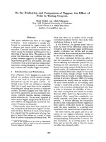
Fig. 1. Schematic representation of the assembly used in a compressed application (a), 2 V cell inserted in a coffee bag envelope (b).
properties is the use of additives, which could have a signifi-
cant effect on its properties, porosity, density, etc. Numerous
kinds of additives [4] have already been tested in order to
improve the performances of lead–acid batteries and, despite
a significant increase of the performances at the beginning of
the battery life, the main long-term drawback met with addi-
tives added in the active mass is an increase ofthe decohesion
phenomenon leading to an acceleration of the capacity loss
[12].
This study proposes an innovative solution in order to im-
prove both cycling life and performance of a very low cost
lead–acid battery by combining the compression concept and
the use of porous additives. Indeed, the paste cohesion will
be maintained owing to the compression system and the elec-
trode porosity will be both improved and maintained during
cycling thanks to the addition of porous compounds, which
will create acid reservoirs within the active material, favour-
ing the diffusion process. The first results concerning the
influence of the compression and the addition of different
additives selected on the cell behaviour are presented in this
paper.
2. Experimental
2.1. Pre-industrial 2V modules preparation
Two volt modules are realized with low cost electrodes re-
sulting from the rolled technology followed by Xmet ‘Prop-
erzi’ process and usually used in a starting lighting ignition
(SLI) applications. Several plates stacks are taken on the pro-
duction batteries line and modified for a compressed appli-
cation thanks to the insertion of a multi-layer separator as
described Fig. 1a. Each constituent element of this separator
has a particular function:
• The micro-porosity of the polyethylene separator put
around the positive electrode allows to facilitate the oxy-
gen release.
• The use of glass fibre separator on the negative electrode
prevents the crushing of the negative active mass.
• The insertion of a corrugated polyethylene spacer guaran-
tees an electrolyte reservoir between the two electrodes
The modified electrode stacks are inserted in a flexible
envelope made from ‘coffee bag’ materials (Fig. 1b). This
material is a current consumer product usually used in the
packaging of foodstuff. Its low cost material is composed of
two thermo-soldering polypropylene foils surrounding thin
aluminium foil allowing a perfect imperviousness to gas and
water.
Finally, two polycarbonate wedges are set out parallel to
the electrode stack and the pressure is applied on the dry
cells thanks to the use of calibrated springs (Fig. 1a). Two
compression rates are tested: 10 and 100 kPa
1
.
2.2. Laboratory modified 2V cell preparation
2.2.1. Additives selected
The selection of additives depends on numerous criteria
in terms of porosity, resistance to acid and positive potential,
dimensions, purity, weight, cost, etc. Three kinds of additives
havebeenretainedfor this firstexperimentscampaign namely
silica-based additives, zeolite and carbon materials.
2.2.1.1. Silica-based additives. The silica-based additives
have been chosen because of their high chemical and electro-
chemical inertia. The two samples tested were powders and
fibres in shape.
The micro-porous silica powder has been furnished by
Daramic. It is commonly used in the manufacture of separa-
tors. It consists of particles agglomerates of which the grain
size is close to 3 m with about 90% of porosity.
The glass fibre samples (Hollingsworth&Vose Co.) are
characterised by a specific area above 0.3 m
2
g
−1
and
1
Equivalence: 100 kPa = 1 bar = 14.503 PSI = 29.625 In. Hg.
548 G. Toussaint et al. / Journal of Power Sources 144 (2005) 546–551
Table 1
Cycling conditions applied to the pre-industrial modules
Discharge C
2
up to U
lim
= 1.25 V
Charge Step 1: I constant = I
2
up to U
lim
= 2.65 V
Step 2: I constant = I
15
up to 115% Ah
particles with an average diameter included between 0.25
and 10 m and by a high length up to 50 m.
2.2.1.2. Zeolite. This compound is oneof the more common
products used in catalysis applications and it has been re-
tained because of its high open porosity. The zeolite chosen
is the ZSM-5 type (Utikon-zeochem) with a pore diameter
close to 0.5 nm. Its particle size has not been characterised
yet.
2.2.1.3. Carbon materials. Those products have been se-
lected because of their electronic conduction properties
among others. The two carbon samples chosen are nanotubes
(cirimat lcmie, Toulouse) and graphite powder (SG) present-
ing a high specific area close to 570 and 40m
2
g
−1
, respec-
tively.Nevertheless,those materialsare notstable versus pos-
itive potential and will be only used in the negative electrode.
2.2.2. Electrode preparation
The modified electrode preparation consists of the addi-
tion of 1–2 wt.% of additives into the original paste formula-
tion. Only the water quantity is adjusted in order to maintain
a satisfactory texture for the pasting operation. Then, naked
rolled grids with a 16 cm
2
area are coated with the modified
paste. Finally the electrodes are dried during a curing stage:
these are put in a steam room at 60
◦
C during 24 h with 100%
of humidity and then 24 h dry.
The cells are composed of the assembly of three plates
in which the modified one is surrounded by the two other
polarities and the multi-layer separator is inserted between
the plates. The cells are tested in a compressed application
with a 100 kPa constraint.
2.3. Electrical tests
2.3.1. Pre-industrial modules
The pre-industrial modules are tested with an acceler-
ated cycling procedure favouring the shedding phenomenon
(Table 1). The test is stopped when the discharge capacity is
lower than 50% of the initial one.
2.3.2. Laboratory cells modified by additives
In order to underline the effect of the additives on the elec-
trical performance of the modified cells, a characterisation
procedure is applied with different discharge rates: C
10
,C
5
and C
2
(Table 2). The test is stopped when the performances
are stabilised, i.e. after 5 cycles at least.
Table 2
Characterisation procedure applied to the laboratory cells modified by
additives
Discharge C
10
up to U
lim
= 1.4 V X 5
Charge I constant = 0.5 I
10
up to 115% Ah
Discharge C
5
up to U
lim
= 1.4 V X 5
Charge I constant = 0.5 I
10
up to 115% Ah
Discharge C
2
up to U
lim
=1V X5
Charge I constant = 0.5 I
10
up to 115% Ah
3. Results
3.1. Compression effect
3.1.1. Electrical behaviour
Fig. 2 represents the evolution of the relative discharge
capacity during the accelerated cycling test. For an uncom-
pressed configuration, the reference achieves only 70 cycles
before reaching the stop conditions. For both compressed
designs, a good stabilisation of the capacity is observed dur-
ing 300 cycles, then a slight decrease of the performances
appears. The stop condition is reached after 500–700 cy-
cles.Moreover,a high compression rate application (100 kPa)
leadsto a lowcapacitylosswithstabilised performances close
to only 90% of the initial capacity.
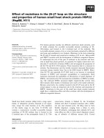
3.1.2. Post mortem analysis
A post mortem analysis has pointed out the cells failure
mode. As seen in Fig. 3a, without compression, the positive
electrodes have suffered more damage since the active mate-
rials are completely broken away from the grids. With a low
compression rate (10 kPa), the positive plates areless defaced
(Fig. 3b). The active material is rather soft and shedding is
observed only on the edges of the plates. A higher pressure
(100 kPa) leads to the integrity of the electrodes being per-
fectly maintained (Fig. 3c).
Finally, for both compressed applications, the formation
of foam at the top of the electrode stack causes short-circuits
responsible forthe premature and of thecycling tests(Fig. 4).
Fig. 2. Relative discharge capacity evolution during the cycling test of the
pre-industrial modules.
G. Toussaint et al. / Journal of Power Sources 144 (2005) 546–551 549
Fig. 3. Photographs of positive electrodes compressed at 0 kPa (a),10 kPa (b) and 100 kPa (c) after the accelerated cycling test.
Fig. 4. Photograph of short-circuit at the top of the electrode stack in a
compressed application.
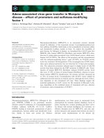
3.2. Effect of additives
Fig. 5 shows the average discharge capacity at different
discharge rates obtained with the modified positives elec-
trodes. Thus, compared to the reference, the electrical be-
haviour of the cell modified with silica-based additives is not
satisfactory. Indeed the powder used has a negative effect
whatever the discharge rates and fibres seem to have no par-
ticular influence. Nevertheless, the test with zeolite is very
interesting since the performances are up by close to 20% on
the reference whatever the discharge rate.
Fig. 6 presents the performances obtained at differ-
ent discharge rates with negative modified electrodes.
The two carbon-based additives tested allow to improve
the cell performances whatever the discharge rates. But
the best behaviour is obtained with graphite powder since the
performances are up to 20–50% on the reference depending
on the discharge rate. The best improvement is obtained
with the higher discharge rate, i.e. C
2
.
4. Discussion
This study has shown the significant effect of the com-
pression application on a flexible module composed of thin
plates stack slightly modified with a multiplication by close
Fig. 5. Average discharge capacity at different discharge rates of the cells with modified positive electrodes.
550 G. Toussaint et al. / Journal of Power Sources 144 (2005) 546–551
Fig. 6. Average discharge capacity at different discharge rates of the cells
with modified negative electrodes.
to 10 of their cycling life in aggressive cycling conditions. In
accordance with several authors [8,13,14], the post mortem
analysis shows the significant influence ofthe pressure onthe
positive plate evolution.The expansion of theactive materials
is limited, suppressing the shedding phenomenon responsi-
ble for the dramatic capacity loss of the cell in such cycling
conditions.
Besides, as noticed by other authors [15,16], a low rate
of compression (10kPa) already allows a significant increase
of the cycling life. But the post mortem analysis of our cells
shows that a low pressure is not sufficient enough to maintain
the positive electrode in a good structural state. Moreover,
the important effect of a high pressure on the active mass
cohesion and the premature end of the test because of short-
circuit are arguments to prefer a high rate of compression.
The decrease ofthe capacityobservedwith a highpressure
(100 kPa) is in accordance with Chang’s studies [7]. This be-
haviourcanbeattributabletotheeffectofthe constraint on the
active mass evolution. Indeed, the pressure could contribute
to the crushing of the porous volume of the active mass limit-
ing the acid diffusion process in the electrode and in the same
way the amount of useful active materials. Consequently, the
capacity is lower because the pressure is high.
The useof porous additivesseems to be a pertinent answer
to this last problem but the negative effects of silica-based
additives on the positive electrode show the difficulties to
find a suitable additive for a compressed application.
Some hypothesis could be advanced in order to explain
this behaviour. Indeed, the porosity of the silica powder is
rather doubtful and the small aggregate size of the powders
could contribute to filling up theexisting porosityof the paste
and to diminish the amount of useful active mass.
Concerning the fibres, the low surface area of this ad-
ditive does not favour the creation of acid reservoirs in-
side the paste, thus the amount of useful active mass is not
improved—explaining the insignificant influence of this ele-
ment on the electrical performance of the cell.
Nevertheless, the addition of zeolite allows to validate the
idea of putting additives with high porosity in a compressed
application. Indeed, it seems that its open porosity is suffi-
ciently large (∅
p
∼ 0.5 nm) to absorb the electrolyte and to
favour diffusion inside the active mass. In other respects, the
influence of the pressure application on the active mass cohe-
sion and consequently on its conduction properties could be
discussed. Thus the increase of the performances observed
with a low rate of discharge, where the acid diffusion prob-
lems are less important, could be partially attributable to an
improvement of the active mass conduction in a compressed
application.
Concerning the tests on the negative electrodes, the good
performances, in particular with a high discharge rate, ob-
tained with carbon materials could be attributed to the high
specific surface ofthis productsinfluencing the acid diffusion
process by actingas an‘electro-osmotic’ agent[17]. This first
experiment campaign does not allow to specify the share of
the influence of the conduction properties of this product on
the improvement of the cell performances.
5. Conclusions
This study has shown the positive effect of the pressure
application on industrial 2 Vcells slightlymodified interm of
both cycling life and capacity. The satisfactory performances
obtained with the slightly compressed cells raise the interest
to find the optimum of the compression to apply and other
tests with pressure lower than 100kPa are necessary.
The idea of using porous additives in the active materials
in order to improve the capacity of the compressed cells has
been validated during this first experiments campaign. Two
additiveshave been retained:zeolite, in the positivepaste, and
graphite powder, in the negative paste, because of their sig-
nificant influence on the electrical performance of the tested
cells.
These last results encourage us to start a second test cam-
paignwith other additivesandin particular with the Diatomite
family. Diatomite is a silica-based porous rock, which comes
fromtheaccumulationof fossilizeddiatom’sskeletons.These
compounds are available in a large range of aggregate size
andseemtofulfilnumerouscriteriainordertobesuccessfully
used in a compressed application.
Acknowledgements
The authors would like to acknowledge ADEME for fi-
nancial support (contract no. 0174046).
References
[1] G. Plant
´
e, Recherches sur l’
´
electricit
´
e, Gautier-Villars Editeur, Paris,
1883, p. 20.
[2] E. Meissner, J. Power Sources 78 (1999) 99–114.
[3] G. Terzaghi, J. Power Sources 73 (1998) 78–85.
G. Toussaint et al. / Journal of Power Sources 144 (2005) 546–551 551
[4] A.J. Ritchie, A literature review, Internal documents, St. JOE Mineral
Corporation.
[5] J. Alzieu, B. Geoffrion, N. Lecaude, J. Robert, Proceedings of the
Sixth International Electric Vehicle Symposium, Philadelphia, Octo-
ber, 1978.
[6] J. Alzieu, J. Robert, J. Power Sources 13 (1984) 93.
[7] T.G. Chang, J. Electrochem. Soc. 131 (8) (1984) 1755.
[8] M. Perrin, Thesis, University of Nancy I, 2001.
[9] J. Landfors, J. Power Sources 52 (1994) 99.
[10] A.F. Hollemkamp, R.H. Newnham, J. Power Sources 67 (1997) 97.
[11] H. Bode, Lead-acid Batteries, Wiley-Intersciences, 1977.
[12] K. McGregor, J. Power Sources 59 (1996) 31.
[13] K. Takahashi, M. Tsubota, K. Yonezu, K. Ando, J. Electrochem.
Soc. 130 (1983) 2144.
[14] J. Alzieu, N. Koechlin, J. Robert, J. Electrochem. Soc. 134 (1987)
1881.
[15] S. Atlung, B. Zachau-Christiansen, J. Power Sources 30 (1990) 131.
[16] E.M.L. Valeriotte, A. Heim, M.S. Ho, J. Power Sources 33 (1991)
187.
[17] P.T. Moseley, J. Power Sources 64 (1997) 47.