administering cisco qos ip networks - chapter 8
Bạn đang xem bản rút gọn của tài liệu. Xem và tải ngay bản đầy đủ của tài liệu tại đây (291.52 KB, 50 trang )
Advanced QoS
Overview
Solutions in this chapter:
■
Using the Resource Reservation Protocol
■
Using Class-Based Weighted Fair Queuing
■
Using Low Latency Queuing
■
Using Weighted Random Early Detection
■
Using Generic Traffic Shaping and Frame
Relay Traffic Shaping
■
Running in Distributed Mode
■
Using Link Fragmentation and Interleaving
■
Understanding RTP Header Compression
Chapter 8
271
110_QoS_08 2/13/01 11:49 AM Page 271
272 Chapter 8 • Advanced QoS Overview
Introduction
This chapter outlines some of the more cutting edge QoS mechanisms available
at press time. Some of these technologies are just beginning to be widely
deployed on production networks, and, though Quality of Service is constantly
being improved and modified, these technologies will undoubtedly remain a sig-
nificant factor in the Quality of Service marketplace for some time to come.
Several of these technologies, such as RSVP and LLQ, are currently being
used mostly for voice applications, and you will find that these more advanced
mechanisms are often used in conjunction with each other, rather than indepen-
dently.These mechanisms, although powerful and useful in their own right, gain
power and functionality when used along with other mechanisms.
Some of the benefits of more advanced queuing mechanisms are increased
granular control of traffic behavior, and the ability to be far more specific when
classifying and queuing or dropping traffic. However, this presents a potential
problem.There is a trade-off between granular control and flexibility of use.
LLQ, for example, is a very specific mechanism with a very specific purpose, but
it not well suited for many things other than that purpose. It is particularly
important in this chapter to pay attention to recommendations about where the
deployment of these technologies is appropriate.
Using the Resource
Reservation Protocol (RSVP)
The Resource Reservation Protocol (RSVP) is the first attempt at an industry
standard implementation of the Internet Integrated Services (Intserv) model of
QoS. Researchers at the Information Sciences Institute (ISI) at the University of
Southern California (USC) and the Xerox Palo Alto Research Center first con-
ceived of RSVP.
NOTE
In 1993, the Internet Engineering Task Force (IETF) started working
toward standardization through an RSVP working group. Version 1 of
this protocol is currently defined by RFC 2205. Interested readers may
find the IETF Applicability Statement (RFC 2208) helpful in pointing out
both the uses and current issues with an RSVP deployment. This chapter
will illustrate both of these briefly.
www.syngress.com
110_QoS_08 2/13/01 11:49 AM Page 272
www.syngress.com
The Intserv model is characterized by applications or end stations reserving
resources across a network to guarantee a particular level of service. RSVP is a
protocol that implements this signaling.
RSVP is independent of, yet complimentary to, Intserv.Whereas Intserv spec-
ifies the set of classes of service and the parameters to deliver QoS, RSVP
requests this service level from network nodes and, in some cases, carries the
Intserv parameters.
RSVP does not provide QoS directly to applications, but instead, coordinates
an overall service level by making reservation requests with as many nodes as pos-
sible across the network. It is up to other QoS mechanisms to actually prevent
and control congestion, provide efficient use of links, and classify and police
traffic. A successful implementation of RSVP requires that it work in conjunction
with these other mechanisms.
RSVP’s popularity lies in its capacity to give guaranteed QoS to real-time
applications that have either constant bandwidth requirements or low latency
requirements.This is why its primary use today on networks is to deliver multi-
media streams such as voice and video.
What Is RSVP?
RSVP is a signaling protocol that makes reservations of resources for client appli-
cations to guarantee a certain QoS. It is considered a signaling protocol because
these reservations are negotiated by communication between end stations.
Furthermore, it is an out-of-band signaling protocol. RSVP packets are not used
to transmit bulk data; they coexist on the network with other packets and are
used to reserve resources for typical IP packets or, more specifically, the IP packets
that make up the flows that are to get specialized QoS.
RSVP makes reservations of resources for data flows across a network.These
reserved flows are usually referred to as sessions. A session is defined as packets
having the same destination address (unicast or multicast), IP protocol ID, and
destination port. Resources could be considered such things as allocated band-
width, CPU cycles, or queuing priority. Clients use RSVP to request a guarantee
of QoS across the network. Routers participate in RSVP by allocating resources
to particular flows, or denying resources if there are none available, and by for-
warding RSVP information to other routers.
Advanced QoS Overview • Chapter 8 273
110_QoS_08 2/13/01 11:49 AM Page 273
274 Chapter 8 • Advanced QoS Overview
NOTE
A signaling protocol can be either in-band or out-of-band, depending on
whether the signaling data flows over the same medium as the bulk
data. In the telephony world, ISDN would be considered an out-of-band
signaling protocol, because all information for setting up a call passes
over a separate D- channel (data), whereas the actual telephone conver-
sation flows over the Bchannels -(bearer). In a way, RSVP could be con-
sidered an in-band signaling protocol, since it flows over the same
physical media, the same data-link layer, and even the same network as
the bulk data. However, it is usually referred to as out-of-band because
the packets are separate from the bulk data. A flow that was set up by
RSVP would have nothing in its packets to indicate that it is participating
in RSVP. The state of active reservations is stored in each routed node.
RSVP is an Internet Control Protocol that resides at Layer 4 of the OSI
model, the transport layer. It is similar to other control protocols, such as Internet
Control Message Protocol (ICMP) and Internet Group Management Protocol
(IGMP). It is fully compliant with Internet Protocol version 4 (IPv4) and the
emerging Internet Protocol version 6 (IPv6). It is not a routing protocol.The
path that it takes across the network is the same as other IP packets and is deter-
mined by the underlying routing protocol (OSPF, EIGRP, BGP, and so forth)
Besides interoperating with routing protocols, RSVP also works with QoS
implementation mechanisms.These are the mechanisms that provide QoS
directly, such as weighted fair queuing (WFQ), weighted random early detection
(WRED), and the like.What implementation mechanisms are used is not the
direct concern of RSVP. It is up to the routers to determine how QoS will be
implemented, based on their own particular capabilities. RSVP only makes the
request and leaves it up to the intermediary nodes to deliver QoS.
Both unicast and multicast traffic are supported by RSVP. Support for multi-
cast is fortuitous, since RSVP is currently used the most prevalently for voice and
video traffic, much of which is characterized by multicast flows.We will see later
how RSVP interoperates with the Internet Group Management Protocol
(IGMP) and Protocol Independent Multicast (PIM) to reserve resources for mul-
ticast flows.
www.syngress.com
110_QoS_08 2/13/01 11:49 AM Page 274
Advanced QoS Overview • Chapter 8 275
NOTE
It is not mandatory that RSVP be enabled everywhere on a network in
order for a reservation to be made. RSVP has the built-in capability to
tunnel over non-RSVP aware nodes (see the discussion later on the setup
process). Though a guaranteed QoS may not be possible in this case, if the
non-RSVP network has sufficient bandwidth, for example, tunneling over a
Gigabit Ethernet or ATM core, it might be feasible for most applications. In
addition, it is not even necessary for the clients to be RSVP capable. Cisco
routers provide RSVP functionality for VoIP dial peers. In the next chapter,
we configure RSVP in a test environment using RSVP proxy—a function
that emulates clients sending RSVP Path and Resv messages.
What RSVP Is Not
RSVP is not a routing protocol. It relies on typical IP routing protocols to for-
ward the RSVP packets.The next section shows how RSVP uses the routed path
to create the setup messages that make the actual reservations.
Because of its protocol-based nature, RSVP does not monitor reservations. It
is, therefore, not a resource manager. It is worth reiterating that it is simply a sig-
naling protocol—client talking to client, router talking to router. It does not actu-
ally control what kinds of resources are reserved, either.That is up to the routers
and their particular capabilities.You can imagine the benefit to a network admin-
istrator of knowing at any given moment how many reservations are made across
the network.This would help for bandwidth planning and provisioning.Although
it is possible to see what reservations are active in the routers, as we will see in
chapter 9, the Resource Reservation Protocol has no capability of providing this
information directly.
Although RSVP is an important QoS mechanism, it is not an implementa-
tion mechanism. It could be better thought of as a mechanism that requests QoS
from other mechanisms. It is not a packet scheduler, link-efficiency mechanism,
or traffic classifier. It does, however, necessarily work with these mechanisms.
Otherwise, there would be no actual QoS—just a reservation!
How Does RSVP Work?
Now that we have a basic understanding of what RSVP is and is not, let us look
at the mechanics of setting up a RSVP session.We leave the specifics of config-
uring RSVP for the next chapter and concentrate for now on the overall strategy.
www.syngress.com
110_QoS_08 2/13/01 11:49 AM Page 275
276 Chapter 8 • Advanced QoS Overview
Session Startup
RSVP is often set up between two clients in a point-to-point situation, or
between multiple senders and multiple recipients (multicast). It is even possible
for RSVP to negotiate a multipoint to single-point transmission. In any case, the
RSVP session startup process reserves resources in a single direction only.To have
full-duplex QoS guarantees, it is necessary for the session startup process to be
performed twice, once in each direction. For example, in the case of setting up a
VoIP call between two telephone users, it would usually be necessary to set up
two reservations, one each way, to guarantee good QoS for both callers. On the
other hand, a video stream would necessitate only a one-way reservation.
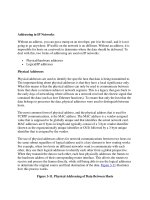
Let us step through the process of a RSVP session startup. In Figure 8.1 we
have two clients across a RSVP-enabled network.At the top we have Client A,
which we will designate as the sender, and at the bottom we have Client B,
which we will consider the receiver.Thus, after the reservation is set up, the bulk
data, whether it is voice, video, or something else, will flow from Client A to
Client B in a downstream manner.
www.syngress.com
Figure 8.1 RSVP Session Startup, Path Messages
Client A
(Sender)
Client B
(Receiver)
Path
Path
Path
Path
110_QoS_08 2/13/01 11:49 AM Page 276
Advanced QoS Overview • Chapter 8 277
The first step is for Client A, the sender, to transmit a RSVP Path message to
Client B, the receiver.This Path message travels across the network according to
the underlying routing protocol. At each hop through the network, the Path mes-
sage is modified to include the current hop. In this way, a history of the route
taken across the network is built and passed to the receiver, Client B.
Now that Client B has the complete route from the Path message, a reserva-
tion (Resv) message is constructed and sent to Client A along the exact reverse
path, as shown in Figure 8.2. At each hop, the router determines if the reservation
can be made, based on available bandwidth, CPU cycles, and so on. If the reser-
vation is possible, resources in the router are allocated, and the Resv packet is for-
warded upstream to the previous hop, based on the information in the Resv
packet.
www.syngress.com
Figure 8.2 RSVP Session Startup, Resv Messages
Client A
(Sender)
Client B
(Receiver)
Resv
Resv
Resv
Resv
110_QoS_08 2/13/01 11:49 AM Page 277
278 Chapter 8 • Advanced QoS Overview
NOTE
In both the Path and Resv messages, the upstream hop is usually referred
to as the previous hop, and the downstream hop is called the next hop.
This terminology is derived from the reference point of the bulk data
moving in a downstream direction, from sender to receiver.
If the reservation is declined, an error message is sent to the receiver, Client
B, and the Resv packet is not forwarded. Only when Client A receives a Resv
packet does it know that it can start sending data and guarantee a particular QoS
to the downstream receiver, Client B.
You may think it is odd for the entire RSVP process to begin with the
sender building the Path message to the receiver.This might be analogous to a
television network deciding that it is time for you to watch your favorite show
and automatically turning on the TV. However, there is usually some kind of
non-RSVP request originating from the receiver to set up this flow.This might
be an H.323 conversation between IP telephony applications, or an IGMP
request to join a multicast group to watch a video clip.
NOTE
Though it is necessary for the sender to first transmit the Path message
before the receiver can transmit the Resv message, RSVP is still consid-
ered receiver-oriented. That is, the receiver of the data flow initiates and
maintains the actual resource reservation used for that flow.
Session Maintenance and Tear-Down
After a session is initiated, it is maintained on the routers as a “soft state.”With a
soft state session, the path connecting two end stations can be renegotiated
without consultation with those end stations.This contrasts with a circuit-
switched network, where the connection between two end stations is a hard con-
nection, and when a failure occurs, the connection is broken.
This soft state session must be refreshed by periodic Path and Resv messages;
otherwise, it will be terminated after a “cleanup timeout” interval. RSVP’s default
interval for this “cleanup timeout” is some multiple of the period of the Path and
www.syngress.com
110_QoS_08 2/13/01 11:49 AM Page 278
Advanced QoS Overview • Chapter 8 279
Resv messages.Therefore, if the router misses a single Path or Resv refresh, it will
not terminate the session.This kind of tolerance is necessary, since there is no
preferential QoS treatment for RSVP messages inherent to the protocol.These
messages are sent as best effort unless some provision has been made otherwise,
such as DiffServ.
These “soft states” are dynamic in response to route changes in the network,
changes in senders or receivers, or changes in the requested QoS.There is no
real difference between the process of initiating a new reservation and refreshing
an old one. In both cases, the Path message is built with the previous hop and
next hop information, and the Resv statement is adjusted with any new QoS
requirements.
NOTE
The refresh interval presents a potential problem when the routing
changes across an IP network. If a route change causes any change to
the shortest path for an active flow, packets will be forwarded over the
new route as best effort until Path and Resv messages are sent along this
new path. When this occurs, it is possible that there may not be the nec-
essary resources to complete the RSVP session. In this case, it is up to the
application to decide whether to terminate the session or continue best-
effort delivery. Therefore, RSVP may not give the desired results in a net-
work with unstable route paths.
Good implementations of RSVP will issue tear-down messages when the
reservation is no longer needed, instead of waiting for the “cleanup timeout” to
remove the session.There are two types of tear-down messages: PathTear and
ResvTear. PathTear messages, like Path messages, flow in the downstream direc-
tion, whereas ResvTear messages, like Resv messages, flow upstream. In addition
to clients issuing immediate requests for tear-downs, routers detecting a session
timeout or a loss of resources will send their own tear-down messages to
upstream (ResvTear) and downstream (PathTear) neighbors.
What Kind of QoS Can I Request with RSVP?
The types of QoS that can be reserved by RSVP are consistent with the Internet
Integrated Services Model.These types are controlled-load and guaranteed-rate.
According to the Intserv definition, controlled-load gives applications service as if
they were traversing an unloaded network. Applications requesting controlled-
www.syngress.com
110_QoS_08 2/13/01 11:49 AM Page 279
280 Chapter 8 • Advanced QoS Overview
load can expect low latency and a low number of packet drops.These applica-
tions are usually considered tolerant real-time applications. An example could be an
adaptive real-time application like the playback of a recorded conference call. On
Cisco routers, controlled-load services are implemented primarily with weighted
random early detection (WRED).We will discuss WRED later in this chapter.
RSVP can also request guaranteed-rate services. According to the Intserv def-
inition, guaranteed-rate delivers assured bandwidth with constant delay.
Applications that require this service to function well are usually considered intol-
erant real-time applications.An example would be delay-sensitive applications like
Voice over IP (VoIP). On Cisco routers, guaranteed-rate services are imple-
mented primarily with weighted fair queuing (WFQ).
NOTE
AlthoughWFQ can provide guaranteed-rate services to applications, it
alone may not be sufficient to assure low latency to delay-sensitive appli-
cations such as VoIP during periods of congestion. IOS version 12.1(3)T
provides support for low latency queuing (LLQ) to RSVP.
Reservation Styles and Merging Flows
When a reservation is made, a set of options can be chosen that is collectively
called the reservation “style.” RSVP supports two classes of reservations, shared
and distinct, and two scopes of reservations, explicit and wildcard.A shared reserva-
tion is a single reservation made for all packets from multiple upstream senders. A
distinct reservation establishes a reservation for each sender. For the scope, an
explicit list can be chosen for the senders, in which each sender is enumerated.
The other scope option is to use a wildcard that implicitly selects all the senders.
These options give rise to three possible reservation styles (see Table 8.1).The
combination of a distinct reservation with a wildcard scope is disallowed and is
therefore not defined.
Table 8.1
RSVP Reservation Styles
Scope Reservations
Distinct Shared
Explicit fixed-filter (FF) style shared-explicit (SE) style
Wildcard not defined wildcard-filter (WF) style
www.syngress.com
110_QoS_08 2/13/01 11:49 AM Page 280
Advanced QoS Overview • Chapter 8 281
These different styles are chosen based on the type of transmitted data that
will comprise the reservation.
Wildcard-Filter (WF) Style
The combination of a shared reservation and a wildcard sender selection gives
the wildcard-filter style. In this style, a single reservation is made and shared by all
upstream senders. Reservations can be thought of as a shared pipe whose size is
the largest of the resource requests from all receivers for that link, independent of
the number of senders.
Shared-Explicit (SE) Style
The combination of a shared reservation and an explicit sender list gives rise to
the shared-explicit style.The SE style creates a single reservation shared by a list
of upstream senders. Both the WF and SE reservation styles are appropriate for
data flows that are known not to interfere with each other.An example of this
would be an audio conference where it could be assumed that the multiple
senders would not typically talk at the same time. It might, however, be wise to
make the reservation twice for an audio conference in order to allow for some
over-talking while still retaining QoS.
Fixed-Filter (FF) Style
The combination of a distinct reservation and an explicit sender list gives rise to
the fixed-filter style. In this style, a distinct reservation is created for data packets
from a particular sender.This reservation is not shared with any other sender.
However, if another receiver is added for that sender, the reservation is not dou-
bled, but merged.This kind of style would be appropriate for video signals where
the data from each sender are different.
An RSVP flow descriptor is the combination of a flowspec and a filterspec.A
flowspec is the QoS requested, and the filterspec is the set of packets to receive this
QoS.When new flows are added to the group of reservations in a node, they will
often need to be merged into a common reservation. In the case of multicast
traffic where the same data is going to multiple recipients, the recipients will still
make a Resv request. It is up to RSVP to join this request with the active reser-
vations.When this is done, the flows are referred to as “merged.”
The RSVP rules do not allow the merging of distinct and shared reserva-
tions, nor the merging of explicit sender selection and wildcard sender selection.
As a result, all three styles are mutually incompatible.
www.syngress.com
110_QoS_08 2/13/01 11:49 AM Page 281
282 Chapter 8 • Advanced QoS Overview
Why Do I Need RSVP on My Network?
RSVP is used primarily to guarantee QoS to real-time applications such as voice
and video. RSVP-aware clients can make a reservation and be guaranteed a good
QoS across the network for the length of the reservation.
www.syngress.com
We have seen that RSVP is largely independent of the media it is running
on with respect to the QoS mechanisms used to implement a particular
reservation. With serial links, WFQ and WRED can be used to provide
either a controlled-load or a guaranteed-rate to an application. These
mechanisms are not appropriate on a shared medium like Ethernet that
has multiple participants competing for the bandwidth. Because of its
end-to-end signaling nature, without a common node to keep track of
active reservations, a RSVP client on a shared medium would have no
way of knowing if there are resources available for the new reservation.
Subnetwork Bandwidth Manager (SBM) was created to implement
RSVP on IEEE 802-based networks (Ethernet/Token Ring). SBM acts very
much like RSVP. On a shared medium, all SBM-enabled nodes elect a
Designated SBM to manage the resources for that network. All RSVP
requests by clients on this network are sent to the DSBM for verification.
If the resources are available, the request is sent on to the destination
address. If the resources are not available, the request is denied.
When using SBM, in order to guarantee that RSVP sessions are not
overwhelmed by non-RSVP traffic, you must ensure that all nodes con-
nected to the shared media are RSVP compliant. This might be difficult
to put into practice.
Depending on the topology, SBM will not always be necessary to
provide good end-to-end service for critical applications. Just because
part of the journey that a packet takes includes a non-RSVP shared
medium such as Ethernet, does not mean that QoS will be impossible.
Consider the case of a switched 100BaseTX network connected to a
WAN via a T1 on a serial interface of a local router. If it can be assumed
that all RSVP requests are destined across the WAN, the bottleneck is
clearly the T1. If there are available resources on the T1, there will prob-
ably be available resources on the Ethernet segment, assuming that non-
RSVP flows do not overwhelm the RSVP sessions.
Subnetwork Bandwidth Manager
110_QoS_08 2/13/01 11:49 AM Page 282
Advanced QoS Overview • Chapter 8 283
Because RSVP takes the Intserv approach to QoS, all traffic in the network
does not need to be classified in order to give proper QoS to RSVP sessions. On
the other hand, for the same reason, a multifield classification must be performed
on each packet at each node in the network to discover if it is part of the RSVP
session for which resources have been reserved.This can lead to a consumption of
network resources like memory and CPU cycles.
RSVP’s open architecture and transparency allow for deployment on many
platforms, and even tunneling across non-RSVP aware nodes. Despite this, RSVP
has some distinct scaling issues that make it doubtful that it will ever be imple-
mented successfully on a very large network, or on the Internet, in its current
revision.These advantages and disadvantages, as well as others previously dis-
cussed, are summarized here.
Advantages of Using RSVP
■
Admissions Control RSVP not only provides QoS, but also helps
other applications by not transmitting when the network is busy.
■
Network Independence/Flexibility RSVP is not dependent on a
particular networking architecture.
■
Interoperability RSVP works inside existing protocols and with other
QoS mechanisms.
■
Distributed RSVP is a distributed service and therefore has no central
point of failure.
■
Transparency RSVP can tunnel across an RSVP-unaware network.
Disadvantages of Using RSVP
■
Scaling Issues Multifield classification and statefulness of reservations
may consume memory and CPU resources.
■
Route Selection and Stability The shortest path may not have avail-
able resources, and the active path may go down.
■
Setup Time An application cannot start transmitting until the reserva-
tion has been completed.
www.syngress.com
110_QoS_08 2/13/01 11:49 AM Page 283
284 Chapter 8 • Advanced QoS Overview
Using Class-Based Weighted
Fair Queuing (CBWFQ)
We saw in Chapter 6 that priority queuing and custom queuing can be used to
give certain types of traffic preferential treatment when congestion occurs on a
low-speed serial link.We also saw that weighted fair queuing (WFQ) accom-
plishes the same effect by automatically detecting conversations and guaranteeing
that no one conversation monopolizes the link. But WFQ has some scaling limi-
tations.The algorithm runs into problems as traffic increases or if it is stressed by
many conversations. Additionally, it does not run on high-speed interfaces such as
ATM. Class-based weighted fair queuing (CBWFQ) was developed to overcome
these factors. CBWFQ carries the WFQ algorithm further by allowing user-
defined classes, which allow greater control over traffic queuing and bandwidth
allocation. CBWFQ provides the power and ease of configuration of WFQ, along
with the flexibility of custom queuing.This advanced queuing mechanism also
incorporates weighted random early detection (WRED).WRED is not necessary
for the operation of CBWFQ but works in conjunction with it to provide more
reliable QoS to user-defined classes.We discuss WRED in more detail later in
this chapter.
CBWFQ is a very powerful congestion management mechanism that is
offered by Cisco for its router platforms. Although it is still being developed to be
even more robust and intelligent, its wide platform support and functionality
warrants it for consideration as part of your overall QoS solution. Let us take a
look at the inner workings of this mechanism.
How Does CBWFQ Work?
Chapter 6 showed that flow-based WFQ automatically detects flows based on
characteristics of the third and fourth layers of the OSI model. Conversations are
singled out into flows by source and destination IP address, port number, and IP
precedence.
If a packet going out an interface needs to be queued because of congestion,
the conversation it is part of is determined, and a weight is assigned based on the
characteristic of the flow. Such weights are assigned to ensure that each flow gets
its fair share of the bandwidth.The weight assigned also subsequently determines
which queue the packet will enter and how it will be serviced.
The limitation of flow-based WFQ is that the flows are automatically deter-
mined, and each flow gets a fair share of the bandwidth.This “fair share” of the
www.syngress.com
110_QoS_08 2/13/01 11:49 AM Page 284
Advanced QoS Overview • Chapter 8 285
bandwidth is determined by the size of the flow and moderated by IP prece-
dence. Packets with IP precedences set to values other than the default (zero) are
placed into queues that are serviced more frequently, based on the level of IP
precedence, and thus get a higher overall bandwidth. Specifically, a data stream’s
weighting is the result of some complex calculations, but the important thing to
remember is that weight is a relative number and the lower the weight of a
packet, the higher that packet’s priority.The weight calculation results in a
weight, but the most important thing isn’t that number—it’s the packet’s specific
handling.Thus, a data stream with a precedence of 1 is dealt with twice as fast as
best-effort traffic. However, even with the action of IP Precedence on WFQ,
sometimes a specific bandwidth needs to be guaranteed to a certain type of
traffic. CBWFQ fulfills this requirement.
CBWFQ extends WFQ to include user-defined classes.These classes can be
determined by protocol,Access Control Lists (ACLs), IP precedence, or input
interfaces. Each class has a separate queue, and all packets found to match the cri-
teria for a particular class are assigned to that queue.
Once the matching criteria are set for the classes, you can determine how
packets belonging to that class will be handled. It may be tempting to think of
classes as having priority over each other, but it is more accurate to think of each
class having a certain guaranteed share of the bandwidth. Note that this band-
width guarantee is not a reservation as with RSVP, which reserves bandwidth
during the entire period of the reservation. It is, instead, a guarantee of band-
width that is active only during periods of congestion. If a class is not using the
bandwidth guaranteed to it, other traffic may use it. Similarly, if the class needs
more bandwidth than the allocated amount, it may use any free bandwidth avail-
able on the circuit.
You can specifically configure the bandwidth and maximum packet limit (or
queue depth) of each class.The weight that is assigned to the class’s queue is cal-
culated from the configured bandwidth of that class.
CBWFQ allows the creation of up to 64 individual classes plus a default class.
The number and size of the classes are, of course, based on the bandwidth. By
default, the maximum bandwidth that can be allocated to user-defined classes is
75 percent of the link speed.This maximum is set so that there is still some band-
width for Layer 2 overhead, routing traffic (BGP, EIGRP, OSPF, and others), and
best-effort traffic. Although not recommended, it is possible to change this max-
imum in aggressive situations in which you want to give more bandwidth to
user-defined classes. In this case, caution must be exercised to ensure that you
allow enough remaining bandwidth to support Layer 2 overhead, routing traffic,
and best-effort traffic.
www.syngress.com
110_QoS_08 2/13/01 11:49 AM Page 285
286 Chapter 8 • Advanced QoS Overview
Each user-defined class is guaranteed a certain bandwidth, but classes that
exceed that bandwidth are not necessarily dropped.Traffic in excess of the class’s
guaranteed bandwidth may use the “free” bandwidth on the link. “Free” is
defined as the circuit bandwidth minus the portion of the guaranteed bandwidth
currently being used by all user-defined classes.Within this “free” bandwidth, the
packets are considered by fair queuing along with other packets, their weight
being based on the proportion of the total bandwidth that was guaranteed to the
class. For example, on a T1 circuit, if Class A and Class B were configured with
1000 Kbps and 10 Kbps, respectively, and if both were transmitting over their
guaranteed bandwidths, the remaining 534 Kbps (1544 – 1010) would be shared
between the two at a 100:1 ratio.
All packets not falling into one of the defined classes are considered part of
the default class (or class-default, as it appears in the router configuration).The
default class can be configured to have a set bandwidth like other user-defined
classes, or configured to use flow-based WFQ in the remaining bandwidth and
treated as best effort.The default configuration of the default class is dependent
on the router platform and the IOS revision. Chapter 9 will discuss the user-
defined classes and default class perform and how they are configured in more
depth.
Even though packets that exceed bandwidth guarantees are given WFQ treat-
ment, bandwidth is, of course, not unlimited.When the fair queuing buffers over-
flow, packets are dropped with tail drop unless WRED has been configured for
the class’s policy. In the latter case, packets are dropped randomly before buffers
totally run out in order to signal the sender to throttle back the transmission
speed.We will see in a later section how WRED interoperates with CBWFQ.
Why Do I Need CBWFQ on My Network?
You might ask yourself, “Why do I need any kind of special queuing?” Packet
based networks drop packets by their very nature. IP network protocols are
designed around the inevitability of dropped packets.The question therefore
becomes,“If you had a choice, which packets would you prefer to keep and
which would you prefer to drop?”This will help determine what type of
queuing mechanism you choose.
WFQ is on by default on low-speed serial interfaces for good reason. It
works well to overcome the limitations of first in/ first out (FIFO) queuing by
not allowing large flows to dominate over smaller, interactive flows, and it is easy
to implement. However, even with the extension of the weighting model by
using IP precedence, flow-based fair queuing is still just that—fair.There are
www.syngress.com
110_QoS_08 2/13/01 11:49 AM Page 286
Advanced QoS Overview • Chapter 8 287
times when the fair slice of the bandwidth pie is less than you require for certain
applications, or when you require more granular control over the QoS provided
to your traffic.When you want a guaranteed bandwidth for particular types of
traffic, you need CBWFQ.
NOTE
Advanced queuing mechanisms (basically, anything except FIFO) work to
schedule which of the packets waiting in queue will be next to go out
the interface. Thus, advanced queuing mechanisms really do not come
into play unless there is congestion. If there are no packets waiting in
queue, then as soon as a packet comes into the router, it goes directly
out of the interface, and the queuing works essentially the same as FIFO.
Therefore, CBWFQ does not “kick in” until congestion starts.
With CBWFQ, you can leverage the DiffServ model to divide all your traffic
into distinct classes to which CBWFQ can subsequently give specialized band-
width guarantees.The typical application of this is to mark traffic at the edge
with IP precedence, and then let mechanisms like CBWFQ give differential
www.syngress.com
Protocols can be categorized as either congestion notification respon-
sive or congestion notification unresponsive. The slow start algorithm
characterizes TCP as being responsive to congestion situations since
when a TCP flow fails to get an acknowledgement that a packet was
received, it throttles back its send rate and then slowly ramps up.
On the other hand, UDP is unresponsive to congestion notification.
Unless there are acknowledgements at a higher layer, a UDP stream will
continue to transmit at the same rate despite packet drops. If we think
of the congested link as the battlefield, and the combatants as TCP and
UDP, then TCP is polite and UDP is usually the spoiler. The unresponsive-
ness of UDP applications can be the detriment of not only other “impo-
lite” UDP streams but also well-behaved TCP sessions.
The Battle of the Internet Protocols
110_QoS_08 2/13/01 11:49 AM Page 287
288 Chapter 8 • Advanced QoS Overview
treatment throughout the entire network according to the service levels defined.
By placing important applications into a class to which CBWFQ can give a guar-
anteed bandwidth, you have effectively prevented other applications from stealing
bandwidth from those critical applications. Let us examine a couple of illustrative
cases.
www.syngress.com
1. Using a SQL Application on a Slow WAN Link
Problem: Imagine that Company A uses a SQL application for central-
ized inventory. It was originally used only at the corporate headquarters;
however, it has now become critical to the core business, and its use has
been extended to remote sites. Unfortunately, because it was developed
in a LAN environment, it does not respond well to delays and packet
loss. Assume that it needs 50 Kbps to function adequately, and that all
the remote sites are connected with 256 Kbps serial links. In the absence
of other traffic, the application functions perfectly. However, at peak
times during the day, other applications such as bulk transfers from FTP,
Telnet sessions to the corporate mainframe, Web browsing, and mes-
saging are periodically filling the link to capacity. With WFQ enabled,
some SQL packets may be dropped in a congestion situation because of
the competing conversations. Remember that all traffic gets its fair share
of the bandwidth and its fair share of packet drops. The drops would
cause TCP retransmissions, which could slow down the SQL application
considerably. Because of the SQL application’s interactive nature, the
user’s productivity drops, and he or she comes to you requesting an
upgrade of the link speed. A circuit upgrade might sound like a good
idea if we could get the project funding. However, if we did this, we
might quickly find out that even if we doubled the circuit speed, the
company’s critical application might still not achieve the performance it
requires. IP networks work in bursts, and even the largest pipes can
momentarily become saturated.
Solution: One solution would be to configure a class for the SQL appli-
cation. The SQL traffic could be classified by the TCP port number of
incoming packets. By applying a policy to the output of the serial inter-
face allocating 50 Kbps to this class, we could guarantee that even in the
busiest part of the day, this application would be given the amount of
Case Studies
Continued
110_QoS_08 2/13/01 11:49 AM Page 288
Advanced QoS Overview • Chapter 8 289
www.syngress.com
bandwidth needed for good performance. In addition, all other traffic
could be configured to function under flow-based WFQ so that all con-
versations would have fair access to the remaining bandwidth.
In effect we have carved out a slice of the serial bandwidth for
the SQL application but also allowed it to use more than this amount,
although its use above 50 Kbps would not be guaranteed. In addition,
other applications can use the reserved 50 Kbps when SQL is not using
it. Remember, CBWFQ does not function unless there is congestion.
2. Total Traffic Classification (CBWFQ in a DiffServ Model)
In the previous case study, we saw that we could effectively guarantee
a certain amount of bandwidth to a mission-critical application. But
what if there were many other applications that needed minimum
bandwidth guarantees? We may need more granular control over how
our applications behave under WFQ. CBWFQ allows us to configure up
to 64 distinct classes. However, we probably would not want to put each
application into a separate class. Not only would we be limited in the
amount of bandwidth we could allocate to the class (the sum of all
bandwidth cannot exceed the link speed), but it could also be confusing
having this many classes.
A best-practice approach would be to define just a few of the
classes, and categorize all applications into these classes based on
expected bandwidth utilization and the application’s tolerance of
dropped packets. With this approach, applications would be sharing
bandwidth with others within the same class, but a degree of granu-
larity is added in addition to WFQ that would be adequate for most net-
works.
We saw in Chapter 4 that the IP ToS header allows us to enu-
merate packets into eight levels of IP precedence, two of them being
reserved for network applications, leaving six levels for user applications.
We can map these IP precedence levels directly into our network classes
of service. Using a precious metal analogy, we would have six classes of
service, as shown in Table 8.2.
In this example, we can realize the economy of using CBWFQ within
the DiffServ model. Using packet classification at the edge of the net-
work to mark IP precedence, we have effectively divided all of our appli-
cations into 5 classes of service plus a default class. Except for the edge
devices, no other classification may be necessary to place a packet into
the proper queue as it traverses the network. By marking applications at
the edge and allowing internal routers to queue packets according to
these classes, we not only assure consistent QoS for that application
Continued
110_QoS_08 2/13/01 11:49 AM Page 289
290 Chapter 8 • Advanced QoS Overview
NOTE
Remember that QoS is never a substitute for bandwidth. On the other
hand, even a gigabit link can drop packets if the queues fill up.
Congestion management rations the limited bandwidth to the most
important applications, or in the case of CBWFQ, ensures that certain
applications get at least the percentage of total bandwidth allocated.
RSVP in Conjunction with CBWFQ
CBWFQ and RSVP can be configured on the same interface.There is, in gen-
eral, no specific interaction between the two.They are configured as if the other
mechanism were not present. However, because RSVP reserves bandwidth for its
clients and CBWFQ guarantees bandwidth for its classes, it is possible to con-
figure the router to guarantee bandwidth to each of them in such a way that the
total guaranteed bandwidth exceeds the circuit speed.
www.syngress.com
across the entire network, but we also reduce the resource load on both
the routers and the network administrator. The routers do not have to
process lengthy ACLs at every hop, and the administrators have to worry
about classification only at the edge of the network. Additionally, it is at
these edge devices that packet rates are the smallest and processor uti-
lization according to packet marking is manageable. To classify packets
at the hub site where many circuits are being aggregated might be too
much for the router to handle.
Table 8.2 An Example of a Class of Service Mapping
Class of Service IP Precedence
Platinum 5
Gold 4
Silver 3
Bronze 2
Iron 1
Best-Effort (default) 0
110_QoS_08 2/13/01 11:49 AM Page 290
Advanced QoS Overview • Chapter 8 291
This constitutes a potential problem. In a congestion situation, if you have
promised the majority of the circuit bandwidth to two mechanisms separately,
which one will succeed in getting the bandwidth it needs? You cannot promise
three-quarters of the bandwidth to CBWFQ and half the bandwidth to RSVP and
expect that they would both have sufficient bandwidth in a congestion situation. In
practice, if you need to guarantee bandwidth to classes as well as to RSVP sessions,
you would avoid an overlapping bandwidth guarantee like this. Still, there is
nothing in the IOS code to prevent you from making this configuration.
So, what exactly does happen if you over-subscribe the guaranteed bandwidth
by promising it to both RSVP and CBWFQ? Because of the WFQ implementa-
tion in the routers, RSVP wins out in the end, taking as much bandwidth as it
needs from all other classes equally.
Using Low Latency Queuing (LLQ)
The previous section demonstrated that CBWFQ can give bandwidth guarantees
to different classes of traffic.Although CBWFQ can provide these bandwidth
guarantees, low latency transmission may not be provided to packets in conges-
tion situations, since all packets are transmitted fairly based on their weight.This
can cause problems for applications like VoIP that are sensitive to delays, especially
variations in delays.Variation in the delay time between individual packets that
make up a voice stream is usually referred to as jitter. Although most voice appli-
cations can tolerate a certain amount of delay, jitter can cause choppiness in voice
transmissions and quickly degrade overall voice quality. Low latency queuing
(LLQ) extends CBWFQ to include the option of creating a strict priority queue.
Strict priority queuing delivers low latency transmission to constant bit rate
(CBR) applications such as voice.
How Does LLQ Work?
Once you know how CBWFQ works, LLQ is easy to understand. LLQ creates a
strict priority queue that you might imagine as resting on top of all other queues.
This priority queue is emptied before any other queue is serviced. A strict pri-
ority queue is often referred to as an exhaustive queue, since packets continue to
be removed from the queue and transmitted until it is empty. Only after the strict
priority queue is totally empty are the other queues serviced in the order deter-
mined by whatever weighting has been configured by the CBWFQ bandwidth
statements.
www.syngress.com
110_QoS_08 2/13/01 11:49 AM Page 291
292 Chapter 8 • Advanced QoS Overview
NOTE
When LLQ was first created, it was referred to as PQCBWFQ, or priority
queuing with class-based weighted fair queuing. Although this lengthy
acronym was appropriate because it clearly described the combined
functionality of PQ with CBWFQ, it has been changed in most documen-
tation to simply LLQ.
If packets come into the priority queue while another queue is being ser-
viced, the packets waiting in the priority queue will be the very next packets sent
out the interface, after the current packet has been transmitted. In this way, the
delay between packets sent from the priority queue is minimized, and low
latency service is delivered.The maximum time between priority packets arriving
at the far end would occur in the case in which a packet arrives in the previously
empty priority queue as soon as the router starts to transmit a large packet.The
largest possible packet is referred to as the maximum transmission unit (MTU),
which is 1500 bytes on Ethernet.The priority packet will have to wait for the
non-priority packet to finish transmitting.Thus, the longest delay possible
between arriving priority packets is limited to the serialization time of the MTU
plus the serialization time of the priority packet itself.The serialization time is
calculated by dividing the size of the packet by the link speed (packet size/link
speed).We discuss the implications of serialization delay and how to overcome it
in more detail in a later section on Link Fragmentation and Interleaving (LFI).
Classifying Priority Traffic
The traffic placed into the priority queue under LLQ is determined by the same
criteria available to any other user-defined class under CBWFQ. Specifically,
these criteria include protocol, Access Control Lists (ACLs), IP precedence, and
input interface.
Allocating Bandwidth
Bandwidth is allocated to the priority class a little differently than to other user-
defined classes. Instead of specifying the guaranteed bandwidth of the class with
the bandwidth command, the priority command is used.This gives a priority class
that will deliver LLQ to all traffic falling under this classification.There is a par-
ticular distinction between how traffic metering is handled with the priority class
as opposed to other user-defined classes. Unlike normal classes, with the priority
www.syngress.com
110_QoS_08 2/13/01 11:49 AM Page 292
Advanced QoS Overview • Chapter 8 293
class under congestion situations, bandwidth in excess of the limit configured
with the priority command is always dropped.This is to prevent the priority queue
from starving other traffic, both other user-defined classes and other important
traffic like network routing updates. However, in non-congestion situations, the
bandwidth allocated to the priority class may be exceeded.
It is important that you limit the bandwidth allocated to the priority class to
a reasonable value. If you configure too much of your traffic as priority traffic,
then it really is not priority at all. On an airplane, if everyone flies first class, can
you really call it first class? Additionally, it is strongly recommended that packets
classified into the priority class be limited to voice traffic alone.Voice streams are
made of small packets of constant bit rate that are well behaved by nature. By
classifying applications into the priority class that are prone to bursts or com-
prised of large packets, you essentially destroy the low latency provided to the
small-packet CBR voice traffic also waiting in the priority queue.
The fact that bandwidth of the priority class under congestion situations cre-
ates a “hard upper limit” to voice traffic should not cause insurmountable prob-
lems.Voice planners are accustomed to providing for an exact number of voice
calls on traditional voice networks.The same can be done on VoIP networks by
multiplying the bandwidth of each voice call (determined by the codec) by the
number of simultaneous calls in order to get the bandwidth necessary. It is
important to note that a call admission control process for the voice calls is
required.This guarantees that the number of calls supported by the bandwidth
provisioned by the priority command is not exceeded. Exceeding this bandwidth
would potentially lead to poor voice performance for all voice callers. Here is an
example.
Consider that a remote site needs up to 24 simultaneous voice calls con-
nected to the main hub site.The remote site is connected via a T1 serial link.
When the G.729 codec is used with compressed RTP (CRTP), you can expect
each call to use a maximum of 12 Kbps.This gives a provision of 288 Kbps for all
24 calls.This bandwidth is configured for the priority class with the priority
command. In an uncongested situation, more than 24 calls could be completed
and still have good quality. However, if congestion occurs in this overloaded call
state, even for a moment, packets will be dropped from the priority queue. Since
it can be assumed that the packets from the individual voice calls are interleaved
with each other, some drops will occur across all connected voice calls, resulting
in poor performance for everyone.To avoid this, some kind of admission control
system is necessary to assure that no more than 24 calls are ever connected.This
can be accomplished in a number of ways, including using gatekeeper technology
www.syngress.com
110_QoS_08 2/13/01 11:49 AM Page 293
294 Chapter 8 • Advanced QoS Overview
available on the Cisco Call Manager, the Cisco AS5300, and Cisco 3640 routers
(IOS 12.1(1)), or by limiting the number of active voice ports on communicating
gateways. In either case, it would be preferable for a caller to get a busy signal
indicating that the call could not be completed, rather than the quality of all con-
nected callers being affected.
Note that it is possible to have multiple classes configured as priority classes.
In this case, the classes are policed and rate-limited individually.That is, although
a single policy map might contain multiple priority classes, all in a single priority
queue, they are each treated as separate flows with separate bandwidth allocations
and constraints.
Limitations and Caveats
A notable difference between the priority class and other user-defined classes
under CBWFQ is that WRED is not available in the priority class. LLQ is to be
used for CBR services, especially VoIP.Voice traffic is UDP-based and therefore
not adaptive to the early packet drop characteristic of WRED. If a packet is
dropped from a UDP stream, UDP will not react to this by reducing the send
rate. Because WRED would be ineffective, configuration of this feature for a pri-
ority class using the random-detect command is disallowed.
Why Do I Need LLQ on My Network?
You should consider using LLQ if you need to provide good QoS to delay- and
jitter-sensitive applications like VoIP. Because LLQ is an extension of CBWFQ, it
complements network designs that are already using CBWFQ to give differential
services to classes of applications.You have only to configure another class and
designate it as “priority” with an appropriate bandwidth limitation to give low
latency service to your real-time applications.
Because LLQ is an extension of CBWFQ, you also have access to all the
matching criteria that is provided normally to CBWFQ.This is in contrast to
RTP priority queuing, which limits match criteria to a UDP port range. Because
one of these matching criteria is IP precedence, the DiffServ model can be lever-
aged to use packet marking at edge devices and allow CBWFQ with LLQ to
give low latency service to designated packets without long Access Control Lists
(ACLs).This speeds up packet processing time and overall performance. LLQ is
also more flexible than RTP priority queuing in that it can be enabled on ATM
virtual circuits (VCs) to allow timely dequeuing of delay sensitive traffic into
ATM networks.
www.syngress.com
110_QoS_08 2/13/01 11:49 AM Page 294
Advanced QoS Overview • Chapter 8 295
Finally, the “hard limit” of the bandwidth for priority classes acts as a sort of
admission control that prevents starving other traffic classes of bandwidth in con-
gested situations.
Using Weighted Random
Early Detection (WRED)
In Chapter 6 we saw that Random Early Detection (RED) can be used as a con-
gestion avoidance mechanism to prevent congestion problems at bandwidth bot-
tlenecks on networks.WRED is the Cisco implementation of RED that
combines the RED algorithm with weighting determined by IP precedence
levels.This effectively gives higher precedence traffic lower drop rates and thus
priority over lower precedence traffic in the network.
How Does WRED Work?
RED works on the basis of active queue management, and it addresses the short-
comings of tail drop.A RED enabled router signals congestion to TCP senders by
dropping packets before the router is actually out of buffer space. Compliant TCP
senders detecting the dropped packets will throttle back the send rate using the
TCP slow start algorithm. RED drops arriving packets randomly so that the
probability of a particular flow having packets dropped is in proportion to the
flow’s share of the bandwidth.Thus, flows using more bandwidth have a greater
chance of dropped packets than flows using small amounts of the overall band-
width.
RED operates by monitoring the buffer level and discarding packets proba-
bilistically (see Figure 8.3) based on minimum and maximum threshold values.
Below the minimum threshold, no packets are dropped; above the maximum
threshold, all packets are dropped.When the buffer is between these two thresh-
olds, the drop rate is calculated as a function of the average queue size.The
average queue size is a running average over time. How responsive this average is
to changes is reflected in the configurable weighting average (discussed later).
Because of the randomness in which packets are dropped, packets across all flows
are dropped at different times, thus preventing the phenomenon of global synchro-
nization commonly associated with tail drop.
www.syngress.com
110_QoS_08 2/13/01 11:49 AM Page 295