Solidification and phase transformations in welding pptx
Bạn đang xem bản rút gọn của tài liệu. Xem và tải ngay bản đầy đủ của tài liệu tại đây (2.97 MB, 36 trang )
Solidification and phase
Solidification and phase
transformations in welding
transformations in welding
Subjects of Interest
Suranaree University of Technology Sep-Dec 2007
Part I: Solidification and phase transformations in carbon steel
and stainless steel welds
Part II: Overaging in age-hardenable aluminium welds
Part III: Phase transformation hardening in titanium alloys
• Solidification in stainless steel welds
• Solidification in low carbon, low alloy steel welds
• Transformation hardening in HAZ of carbon steel welds
Tapany Udomphol
Objectives
Objectives
This chapter aims to:
• Students are required to understand solidification and
phase transformations in the weld, which affect the weld
microstructure in
carbon steels, stainless steels,
aluminium
alloys and titanium alloys.
Suranaree University of Technology Sep-Dec 2007
Tapany Udomphol
Introduction
Introduction
Suranaree University of Technology Sep-Dec 2007
Tapany Udomphol
Suranaree University of Technology Sep-Dec 2007
Part I: Solidification in carbon
steel and stainless steel welds
• Carbon and alloy steels with
higher strength levels are more
difficult to weld due to the risk of
hydrogen cracking.
Fe-C phase binary phase diagram.
• Austenite to ferrite transformation
in low carbon, low alloy steel
welds.
• Ferrite to austenite transformation
in austenitic stainless steel welds.
• Martensite transformation is not
normally observed in the HAZ of a
low-carbon steel.
• Carbon and alloy steels are more frequently welded than any other materials
due to their widespread applications and good weldability.
Solidification in stainless steel welds
Solidification in stainless steel welds
Suranaree University of Technology Sep-Dec 2007
• Ni rich stainless steel first
solidifies as primary dendrite
of
γ
γγ
γ
austenite with
interdendritic
δ
δδ
δ
ferrite.
• Cr rich stainless steel first
solidifies as primary
δ
δ δ
δ
ferrite. Upon
cooling into
δ+γ
δ+γδ+γ
δ+γ
region, the outer
portion (having less Cr) transforms
into
γ
γγ
γ
austenite, leaving the core of
dendrite as skeleton (vermicular).
• This can also transform into lathly
ferrite during cooling.
Solidification and post solidification
transformation in Fe-Cr-Ni welds
(a) interdendritic ferrite,
(b) vermicular ferrite (c ) lathy ferrite
(d) section of Fe-Cr-Ni phase
diagram
Tapany Udomphol
Solidification in stainless steel welds
Solidification in stainless steel welds
Suranaree University of Technology Sep-Dec 2007
• Weld microstructure of high Ni
310 stainless steel (25%Cr-
20%Ni-55%Fe) consists of primary
austenite dendrites and
interdendritic
δ
δδ
δ
ferrite between
the primary and secondary dendrite
arms.
• Weld microstructure of high Cr
309 stainless steel (23%Cr-
14%Ni-63%Fe) consists of primary
vermicular or lathy
δ
δδ
δ
ferrite in an
austenite matrix.
• The columnar dendrites in both
microstructures grow in the
direction perpendicular to the tear
drop shaped weld pool
boundary.
Solidification structure in (a) 310 stainless
steel and (b) 309 stainless steel.
Austenite dendrites and
interdendritic δ
δδ
δ ferrite
Primary vermicular or lathy
δ
δδ
δ ferrite in austenite matrix
Tapany Udomphol
Solidification in stainless steel welds
Solidification in stainless steel welds
Suranaree University of Technology Sep-Dec 2007
Quenched solidification structure near the pool of an
autogenous GTA weld of 309 stainless steels
Primary
δ
δδ
δ
ferrite
dendrites
• A quenched structure of ferritic
(309) stainless steel at the weld pool
boundary during welding shows
primary
δ
δδ
δ
ferrite dendrites before
transforming into vermicular ferrite
due to
δ
δδ
δ
γ
γγ
γ
transformation.
Tapany Udomphol
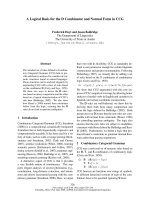
Mechanisms of ferrite formation
Mechanisms of ferrite formation
Suranaree University of Technology Sep-Dec 2007
• The Cr: Ni ratio controls the
amount of vermicular and lathy ferrite
microstructure.
Cr : Ni ratio
Vermicular & Lathy ferrite
• Austenite first grows epitaxially from
the unmelted austenite grains at the
fusion boundary, and
δ
δδ
δ
ferrite soon
nucleates at the solidification front in the
preferred <100> direction.
Lathy ferrite in an
autogenous GTAW of
Fe-18.8Cr-11.2Ni.
Mechanism for the formation of vermicular
and lathy ferrite.
Tapany Udomphol
Prediction of ferrite contents
Prediction of ferrite contents
Suranaree University of Technology Sep-Dec 2007
Schaeffler proposed ferrite content prediction from Cr and Ni
equivalents (ferrite formers and austenite formers respectively).
Schaeffler diagram for predicting weld ferrite content and solidification mode.
Tapany Udomphol
Effect of cooling rate on solidification mode
Effect of cooling rate on solidification mode
Suranaree University of Technology Sep-Dec 2007
Cooling rate
Low Cr : Ni ratio
High Cr : Ni ratio
Ferrite content decreases
Ferrite content increases
• Solid redistribution during solidification is reduced at high cooling rate
for low Cr: Ni ratio.
• On the other hand, high Cr : Ni ratio alloys solidify as
δ
δδ
δ
ferrite as the
primary phase, and their ferrite content increase with increasing cooling
rate because the
δ
δδ
δ
γ
γγ
γ
transformation has less time to occur at high
cooling rate.
Note: it was found that if N
2
is introduced into the weld metal (by adding
to Ar shielding gas), the ferrite content in the weld can be significantly
reduced. (Nitrogen is a strong austenite former)
High energy beam
such as EBW, LBW
Tapany Udomphol
Ferrite to austenite transformation
Ferrite to austenite transformation
Suranaree University of Technology Sep-Dec 2007
• At composition C
o
, the alloy
solidifies in the primary ferrite mode
at low cooling rate such as in
GTAW.
• At higher cooling rate, i.e., EBW,
LBW, the melt can undercool below
the extended austenite liquidus (C
L
γ
γγ
γ
)
and it is thermodynamically possible
for primary austenite to solidify.
• The closer the composition close to
the three-phase triangle, the easier
the solidification mode changes from
primary ferrite to primary austenite
under the condition of undercooling.
Cooling rate
Ferrite
austenite
Section of F-Cr-Ni phase diagram showing
change in solidification from ferrite to
austenite due to dendrite tip undercooling
Weld centreline austenite in an autogenous GTA weld of
309 stainless steel solidified as primary ferrite
Primary
δ
δδ
δ ferrite
γ
γγ
γ austenite
At compositions close to
the three phase triangle.
Tapany Udomphol
Ferrite dissolution upon reheating
Ferrite dissolution upon reheating
Suranaree University of Technology Sep-Dec 2007
• Multi pass welding or repaired
austenitic stainless steel weld consists
of as-deposited of the previous weld
beads and the reheated region of the
previous weld beads.
• Dissolution of
δ
δδ
δ
ferrite occurs
because this region is reheated to
below the
γ
γγ
γ
solvus temperature.
• This makes it susceptible to
fissuring under strain, due to lower
ferrite and reduced ductility.
Effect of thermal cycles on ferrite
content in 316 stainless steel weld (a)
as weld (b) subjected to thermal cycle
of 1250
o
C peak temperature three times
after welding.
Primary
γ
γγ
γ
austenite dendrites (light)
with interdendritic
δ
δδ
δ
ferrite (dark)
Dissolution of δ
δδ
δ ferrite after thermal
cycles during multipass welding
Tapany Udomphol
Solidification in low carbon steel welds
Solidification in low carbon steel welds
Suranaree University of Technology Sep-Dec 2007
• The development of weld microstructure in low carbon steels
is schematically shown in figure.
• As austenite
γ
γγ
γ
is cooled down from
high temperature, ferrite
α
αα
α
nucleates
at the grain boundary and grow inward
as Widmanstätten.
• At lower temperature, it is too slow for
Widmanstätten ferrite to grow to the
grain interior, instead acicular ferrite
nucleates from inclusions
• The grain boundary ferrite is also
called allotriomorphic.
Continuous Cooling Transformation
(CCT) diagram for weld metal of low
carbon steel
Tapany Udomphol
Weld microstructure
Weld microstructure
in low
in low
-
-
carbon steels
carbon steels
Suranaree University of Technology Sep-Dec 2007
A: Grain boundary ferrite
B: polygonal ferrite
C: Widmanstätten ferrite
D: acicular ferrite
E: Upper bainite
F: Lower bainite
Weld microstructure of low carbon steels
A
D
C
B
E
F
Note: Upper and lower bainites can
be identified by using TEM.
Which weld microstructure
is preferred?
Tapany Udomphol
Weld microstructure of acicular ferrite
Weld microstructure of acicular ferrite
in low carbon steels
in low carbon steels
Suranaree University of Technology Sep-Dec 2007
Weld microstructure of predominately
acicular ferrite growing at inclusions.
Inclusions
Acicular ferrite and inclusion particles.
Acicular ferrite
Tapany Udomphol
Factors affecting microstructure
Factors affecting microstructure
Suranaree University of Technology Sep-Dec 2007
• Cooling time
• Alloying additions
• Grain size
• Weld metal oxygen content
Effect of alloying additions,
cooling time from 800 to
500
o
C, weld oxygen
content, and austenite
grain size on weld
microstructure of low
carbon steels.
GB and Widmanstätten ferrite acicular ferrite bainite
GB and Widmanstätten ferrite acicular ferrite bainite
GB and Widmanstätten ferrite acicular ferrite bainite
inclusions prior austenite grain size
Note: oxygen content is favourable for acicular ferrite
good toughness
Tapany Udomphol
Weld metal toughness
Weld metal toughness
Suranaree University of Technology Sep-Dec 2007
• Acicular ferrite is desirable because it improves toughness of the weld
metal in association with fine grain size. (provide the maximum resistance to
cleavage crack propagation).
Acicular ferrite
Weld toughness
Subsize Charpy V-notch toughness values as a function of
volume fraction of acicular ferrite in submerged arc welds.
Tapany Udomphol
Weld metal toughness
Weld metal toughness
Suranaree University of Technology Sep-Dec 2007
• Acicular ferrite as a function of oxygen content, showing the optimum
content of oxygen (obtained from shielding gas, i.e., Ar + CO
2
) at ~ 2% to
give the maximum amount of acicular ferrite highest toughness.
Acicular ferrite
Weld toughness
Transition temperature at 35 J
Oxygen content
Note: the lowest transition temperature is at 2 vol% oxygen equivalent,
corresponding to the maximum amount of acicular ferrite on the weld toughness.
Tapany Udomphol
Transformation hardening in
Transformation hardening in
carbon and alloy steels
carbon and alloy steels
Suranaree University of Technology Sep-Dec 2007
(a) Carbon steel weld (b) Fe-C phase diagram
If rapid heating during welding on phase transformation is neglected;
• Fusion zone is the are above the
liquidus temperature.
• PMZ is the area between peritectic
and liquidus temperatures.
• HAZ is the area between A
1
line and
peritectic temperature.
• Base metal is the area below A
1
line.
Note: however the thermal cycle in
welding are very short (very high
heating rate) as compared to that
of heat treatment. (with the
exception of electroslag welding).
Tapany Udomphol
Transformation hardening in welding
Transformation hardening in welding
of carbon steels
of carbon steels
Low carbon steels (upto 0.15%C) and
mild steels (0.15 - 0.30%)
Medium carbon steels (0.30 - 0.50%C)
and high carbon steels (0.50 - 1.00%C)
Suranaree University of Technology Sep-Dec 2007
Tapany Udomphol
Transformation hardening in low carbon steels
Transformation hardening in low carbon steels
and mild steels
and mild steels
Suranaree University of Technology Sep-Dec 2007
Carbon steel weld and possible
microstructure in the weld.
• Base metal (T < A
C1
) consists of
ferrite and pearlite (position A).
• The HAZ can be divided into
three regions;
Position B: Partial grain-refining
region
Position D: Grain-coarsening region
Position C: Grain-refining region
T > A
C1
: prior pearlite colonies
transform into austenite and expand
slightly to prior ferrite upon heating,
and then decompose to extremely fine
grains of pearlite and ferrite during
cooling.
T > A
C3
: Austenite grains decompose
into non-uniform distribution of small
ferrite and pearlite grains
during cooling due to limited
diffusion time for C.
T >> A
C3
: allowing austenite grains to
grow, during heating and then during
cooling. This encourages ferrite to grow
side plates from the grain boundaries
called Widmanstätten ferrite.
Tapany Udomphol
Transformation hardening in low carbon steels
Transformation hardening in low carbon steels
and mild steels
and mild steels
Suranaree University of Technology Sep-Dec 2007
HAZ microstructure of a gas-tungsten
arc weld of 1018 steel.
(a) Base metal
(c) Grain refining
(b) Partial grain refining
(d) Grain coarsening
Mechanism of partial grain refining
in a carbon steel.
Tapany Udomphol
Transformation hardening in low carbon steels
Transformation hardening in low carbon steels
and mild steels
and mild steels
Suranaree University of Technology Sep-Dec 2007
Multipass welding of
low carbon steels
• The fusion zone of a weld pass can be
replaced by the HAZs of its subsequent
passes.
• This grain refining of the coarsening
grains near the fusion zone has been
reported to improve the weld metal
toughness.
Grain refining in multipass welding (a)
single pass weld, (b) microstructure of
multipass weld
Note: in arc welding, martensite is not
normally observed in the HAZ of a low carbon
steel, however high-carbon martensite is
observed when both heating rate and cooling
rate are very high, i.e., laser and electron
beam welding.
Tapany Udomphol
Transformation hardening in low carbon steels
Transformation hardening in low carbon steels
and mild steels
and mild steels
Suranaree University of Technology Sep-Dec 2007
Phase transformation by high
energy beam welding
HAZ microstructure of 1018 steel produced by
a high-power CO
2
laser welding.
• High carbon austenite in position B transforms into hard and brittle
high carbon martensite embedded in a much softer matrix of ferrite
during rapid cooling.
• At T> A
C3
, position C and D, austenite transformed into martensite
colonies of lower carbon content during subsequent cooling.
A
B
C
D
Tapany Udomphol
Transformation hardening in medium
Transformation hardening in medium
and high carbon steels
and high carbon steels
Suranaree University of Technology Sep-Dec 2007
• Welding of higher carbon steels is more
difficult and have a greater tendency for
martensitic transformation. in the HAZ
hydrogen cracking.
HAZ microstructure of TIG weld of 1040 steel
• Base metal microstructure of higher
carbon steels (A) of more pearlite
and less ferrite than low carbon and
mild steels.
• Grain refining region (C) consists
of mainly martensite and some areas
of pearlite and ferrite.
• In grain coarsening region (D),
high cooling rate and large grain size
promote martensite formation.
martensite
Pearlite
(nodules)
Ferrite and
martensite
Pearlite
Tapany Udomphol