5000M CNC Programming and Operations Manual P2 pdf
Bạn đang xem bản rút gọn của tài liệu. Xem và tải ngay bản đầy đủ của tài liệu tại đây (385.08 KB, 20 trang )
CNC Programming and Operations Manual
P/N 70000508D - Manual Operation and Machine Setup
All rights reserved. Subject to change without notice. 3-3
25-July-03
Manual Panel Keys
Manual panel keys allow you to control machine movements manually.
These keys are located on the Manual Panel. Refer to Table 3-1.
Table 3-1, Manual Operation Keys
Label/Name Key Face Purpose
Handwheel
Moves the selected controlled axis while in the Manual
Mode. Jog must be set to 1, 10, or 100. Optional.
Axis Select
YU
In Manual Mode, selects the axis to be jogged.
JOG
Cycles the CNC through manual movement modes (FEED,
RAPID, 100, 10, 1). The machine builder sets Default rapid
and feed rates at setup.
NOTE: The machine builder determines the actual speed of
the machine during a move.
SPINDLE
OVERRIDE
Overrides the programmed spindle RPM rate. It is a
13-position rotary switch that ranges from 40 to 160 percent.
(Each increment adjusts the spindle override by 10%.) This
feature can be used only on machines with programmable
spindles.
FEEDRATE
OVERRIDE
Overrides the feed and/or rapid rate of the axes in Manual,
Auto, and Single Step modes. It is a 13-position rotary
switch, which ranges from 0 to 120 percent. (Each
increment adjusts the feedback override by 10%.)
NOTE: The override range for rapid rate is 100%. The CNC
will not exceed the maximum rapid rate.
SERVO RESET
Activates the servo motors.
SPINDLE
FORWARD
Starts the spindle in a forward direction.
NOTE: On some machines, you must provide the gear
range and RPM before you activate this key.
SPINDLE
REVERSE
Starts the spindle in a reverse direction.
NOTE: On some machines, you must provide gear range
and RPM before you activate this key.
SPINDLE OFF
Stops the spindle.
(Continued…)
SPINDLE
CNC Programming and Operations Manual
P/N 70000508D - Manual Operation and Machine Setup
3-4 All rights reserved. Subject to change without notice.
25-July-03
Table 3-1, Manual Operation Keys (Continued)
Label/Name Key Face Purpose
START
Starts all machine moves except jog.
JOG +
Moves the selected axis in the positive direction. Available in
all modes. Feedrate specified by the machine builder.
JOG -
Moves the selected axis in a negative direction. Available in
all modes. Feedrate is specified by the machine builder.
HOLD
Halts any running program or programmed move. Press
START to continue.
E-STOP
Press
E-STOP to halt all axes and machine-related functions.
When you activate
E-STOP, the servo motors and any
programming operations shut down. The CNC defaults to
Manual Mode.
Use
E-STOP for emergency shutdown or intentional servo
shutdown.
Manual Panel LEDs
The following keys have LEDs located directly above them on the Manual
Panel. When any of the keys is activated, the corresponding LED lights
up. Refer to Figure 3-1, Manual Panel
.
Servo Reset
Spindle Off
Spindle Forward
Spindle Reverse
The Coolant Ready LED is also located on the Manual Panel. Some
CNCs have a coolant ready M-function. For these CNCs, the Coolant
Ready LED lights when the coolant is ready. The coolant is programmed
to come on when the machine receives a
SPINDLE ON command.
CNC Programming and Operations Manual
P/N 70000508D - Manual Operation and Machine Setup
All rights reserved. Subject to change without notice. 3-5
25-July-03
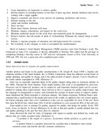
Manual Mode Screen
In Manual Mode, the CNC displays the Manual screen. The Manual
screen is the basic operating screen and is displayed when the CNC is
turned on. All other operating screens are similar in appearance and
selected from the Manual screen soft keys. When the Manual Mode is
active, the Manual (F4) soft key label highlights. Refer to Figure 3-2.
Figure 3-2, Manual Screen
The Manual screen is divided into the following areas.
Program Area Displays the working program name, running
status, mode of operation, in-position check, and
command line.
Command Line Allows you to enter commands manually.
Message Line Displays messages, prompts and reminders.
Machine Position Display
Displays machine’s X, Y, and Z position
coordinates in reference to Machine Home.
Motion Display Area
Displays machine’s X, Y, and Z position coordinates
in reference to:
Part Zero
Target
Distance To Go
Machine Status Display Area
Displays operating information.
Program Area
Command Line
Message Line
Machine Position
Display
Motion Display
Area
Machine Status
Display Area
Active Soft Key
(Highlighted)
CNC Programming and Operations Manual
P/N 70000508D - Manual Operation and Machine Setup
3-6 All rights reserved. Subject to change without notice.
25-July-03
Active Soft Key Identifies the function of the soft key. Soft key
functions change from screen to screen. A
highlighted label indicates an active mode.
Machine Status Display Area Labels
TOOL: Active tool.
DIA: Active tool diameter.
LENG: Z-Axis Tool-Length Offset for active tool.
G: Active G-Codes.
M: Active M-Codes.
RPM: Current spindle speed in revolutions per minute.
FEED: Current feed rate (in inch/mm per minute).
% RPM: Spindle override setting (40% to 160%).
% Feed: Feedrate override setting (0% to 120% for Feed moves
and 0% to 100% for Rapid moves).
LOOP: Loop counter. Counts subprogram repetitions.
DWELL: Seconds remaining in a dwell.
OVERRIDE: Indicates whether the feedrate override setting applies to
both feed and rapid moves or only to feed moves.
PARTS: Number of parts. Resets to zero when you enter Auto or
Single Step mode.
TIMER: Indicates the amount of time per part and accumulated
amount of time (in parentheses) for all parts. Resets to
zero when you enter Auto or Single Step mode.
FIXTURE: Displays active fixture (G53).
Program Area Labels
Blk: Block number (is displayed in S. Step or Auto Mode
only).
PROGRAM: Name of loaded program.
HALTED/*HALTED/RUNNING:
No asterisk: Machine is in a programmed hold or
has completed its program.
With asterisk: External hold has been activated by
an event or
HOLD was pressed.
RUNNING: Program is running.
MANUAL/AUTO/S.STEP:
Current operating mode.
IN-POSN: Is displayed if the machine has reached a
programmed endpoint.
COMMAND: Enters commands in Manual Mode.
CNC Programming and Operations Manual
P/N 70000508D - Manual Operation and Machine Setup
All rights reserved. Subject to change without notice. 3-7
25-July-03
Manual Mode Settings
Features (or settings) that remain active for more than one operation are
said to be modal. Modal features remain active until you change or
cancel them. Most CNC functions are modal.
For example, if the CNC is in Rapid Mode, it executes all moves at the
rapid rate until you initiate Feed Mode. The CNC can be in several
modes, as long as the modes do not conflict.
Before making a manual move, make any necessary mode settings.
Modes set from the Manual screen remain active if the CNC is put in a
program mode (Auto, S.Step) until the program or operator changes the
mode.
Set the following modes from the Manual screen:
Position Mode: Absolute or Incremental Mode
Move Mode: Rapid or Feed Mode
The Active tool: Active tool, tool-length offsets, and tool-nose
radius compensation
Measurement Mode: Inch or MM Mode
The Manual screen determines the following:
The location of Machine Home position
The location of Part Zero
Manual Mode provides the following types of moves:
Jog (Conventional)
Jog (Continuous)
Manual Data Input (MDI)
Handwheel (optional)
CNC Programming and Operations Manual
P/N 70000508D - Manual Operation and Machine Setup
3-8 All rights reserved. Subject to change without notice.
25-July-03
Table 3-2 describes the active soft keys in Manual Mode.
Table 3-2, Manual Mode Soft Keys
Label Soft Key Function
Help F1
Activates the Help Mode.
Program F2
Lists the user programs.
Edit F3 Activates the Edit Mode. A program
must first be selected.
Manual F4 Activates Manual Mode from Auto and
S.Step.
S.Step F5
Changes to Single Step Mode
Auto F6 Changes to Auto Mode. Use to run part
programs for production.
Delete F7
Deletes a character from the command
line in Manual Mode.
Insert F8
Puts the cursor in Insert Mode. Typed
text is inserted without overwriting the
existing text.
Tool F9
Displays the Tool Page. The Tool Page
stores tool diameter, length offsets, and
wear factors.
Handwheel F10
Activates or deactivates Handwheel
Mode. Use to jog any controlled axis in
Manual Mode.
Exit SHIFT + F10
Exits the Control Software and returns
to the Software options screen.
Message F1
Displays the last 10 messages, both old
(already read) and new (not yet read).
Teach F5
Captures a display readout of axis
positions and saves it in a program.
Home F7
Executes the machine homing function.
EXIT F10
Quits the screen and returns to the
Software Startup menu.
CNC Programming and Operations Manual
P/N 70000508D - Manual Operation and Machine Setup
All rights reserved. Subject to change without notice. 3-9
25-July-03
Activating Manual Mode Rapid or Feed
Turn the JOG rotary switch to cycle through all available Jog Modes.
Choose Rapid or Feed mode. The CNC displays the active Feed or
Rapid Mode in the Machine Status Display Area.
NOTE: In Manual Mode, press R then press ENTER to toggle the
override setting between the following selections:
FEED and RAPID rate override (FEED, RAPID)
FEED rate override (FEED)
Toggle the setting to apply the current override selection to the
programmed rates.
Adjusting Rapid Move Speed
The FEEDRATE OVERRIDE rotary switch also adjusts the speed of Rapid
moves. If FEED, RAPID is set, every click of the
FEEDRATE OVERRIDE
rotary switch adjusts the rapid rate by 10% of the default speed. The
switch provides a range of 0% to 100%. Set the switch to 100 to set the
rapid rate. The maximum override rate for rapid speeds is 100%.
NOTE: The machine builder determines the default rapid rate at setup.
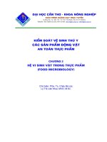
Absolute Mode
In Absolute Mode, all positions are measured from Absolute Zero.
Absolute Zero is X0, Y0, and Z0 when the Absolute Mode is active. You
can move Absolute Zero to any convenient location. All absolute XYZ
positions are measured from this point. Refer to G53 and G92 in
“Section 4 - Preparatory Functions: G-Codes
” for more information on
setting absolute zero. Setting Absolute Zero to a location on the part is
referred to as setting Part Zero. Refer to Figure 3-3.
Figure 3-3, Absolute Positioning
CNC Programming and Operations Manual
P/N 70000508D - Manual Operation and Machine Setup
3-10 All rights reserved. Subject to change without notice.
25-July-03
NOTE: To determine the Z-axis location of Part Zero, set tool length
offsets for each tool.
NOTE: The location of Absolute Zero can be restored after a shutdown
if the machine has the Home function installed.
CAUTION: If Part Zero is not correctly located, the CNC will not
position correctly in Absolute Mode.
Jog Moves
You can make or change jog moves when:
The CNC is in Manual Mode, the Teach Mode, or the Tool
Page; and
The servos are on.
The actual rate for each mode is determined at machine setup. Use the
JOG rotary switch to cycle the CNC through the Jog Mode choices. Refer
to Table 3-3 for the available Jog Modes.
Table 3-3, Jog Moves
Mode Description
Rapid
Default rapid speed for continuous jogs. Actual speed
determined at machine setup.
Feed Continuous jog at feedrate determined at machine setup.
Jog: 100
Conventional Jog Mode, increment set to 100 times machine
resolution.
Jog: 10
Conventional Jog Mode, increment set to 10 times machine
resolution.
Jog: 1
Conventional Jog Mode, increment set to actual machine
resolution.
You can change the Jog Mode any time the CNC is in Manual Mode.
Changing the Jog Mode
NOTE: Jog move modes, with the exception of Jog Rapid Mode, are
performed in Feed Mode.
To change the Jog Mode:
1. In Manual Mode, turn the
JOG switch to select a jog feed rate.
Selecting an Axis
To select an axis in the Manual Mode:
1. Use the
AXIS SELECT rotary switch to cycle through the available axes.
Turn the switch until the indicator points to the required axis.
CNC Programming and Operations Manual
P/N 70000508D - Manual Operation and Machine Setup
All rights reserved. Subject to change without notice. 3-11
25-July-03
Jogging the Machine (Incremental Moves)
In Manual Mode, position the machine with jog increments. To make a jog
increment move:
1. Use
AXIS SELECT to select an axis.
2. Use
JOG to cycle through the move mode choices and choose a Jog
Mode.
3. Press
JOG+ or JOG- to choose a direction. Do not hold down the key.
Each time the key is pressed, the machine jogs along the selected
axis by the selected increment.
Jogging the Machine (Continuous Moves)
From the Manual screen, move the machine at feedrate or at the Jog
Rapid Rate. The machine builder determines the effective jog and feed
rates at setup.
1. In Manual Mode with the Manual screen active, use the
AXIS SELECT
to select an axis.
2. Use
JOG to select a Continuous Jog Mode (Feed or Rapid).
3. Press and hold down + or - to jog the machine in the desired direction.
The machine jogs along the selected axis. To stop the machine,
release the key.
Manual Data Input Mode
Manual Data Input (MDI) Mode allows you to command moves without
creating a part program. MDI also is a quick way to program one move,
or a series of moves that will be used only one time.
To execute a command, type an instruction on the COMMAND: line of
the Program Area, and press
START. (In Manual Mode, the cursor rests
on the command line.)
More than one command can be programmed at a time. Use a semicolon
(;) to separate the commands.
Press
HOLD to pause one-shot moves.
Press
START to continue. Press Manual (F4) to cancel. MDI moves are
executed only once. To recall a previously commanded block, press
UP
ARROW.
CAUTION: You must know the location of the Absolute Zero
before making Absolute Mode moves.
CNC Programming and Operations Manual
P/N 70000508D - Manual Operation and Machine Setup
3-12 All rights reserved. Subject to change without notice.
25-July-03
Using Manual Data Input Mode
To use Manual Data Input Mode:
1. In Manual Mode, type the command block(s) at the COMMAND: line.
2. Press
START to execute the typed commands.
Most functions that can be commanded in a part program can also be
commanded in MDI Mode. These include:
G00, G01, G02, G03 moves
M-Codes, T-Codes (tool activation), S-Codes (spindle speed)
Modal commands (G90, G91, G70, G71, etc.)
G-Codes (G92, G28, G53, etc.)
The following example demonstrates how MDI Mode might be used to
activate the spindle.
COMMAND: M43; G97 S600; M3
M43 Activates Gear Range defined by M43 in setup
G97 S600 Activates Specified Spindle Speed
M3 Activates Spindle Forward
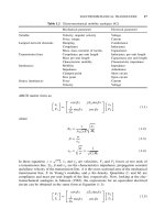
Operating the Handwheel (Optional)
NOTE: The handwheel operation described here assumes that the
handwheel has been properly installed and configured in the
Setup Utility. The handwheel soft key will not display unless the
Setup Utility has been configured for handwheel use.
The CNC supports an option that allows you to move a selected axis via a
remote handwheel.
The resolution of the handwheel depends on the Jog Mode. Refer to
Figure 3-4, Handwheel Operation
.
CNC Programming and Operations Manual
P/N 70000508D - Manual Operation and Machine Setup
All rights reserved. Subject to change without notice. 3-13
25-July-03
Figure 3-4, Handwheel Operation
To select a Jog Mode:
1. Turn the rotary switch to select an axis.
2. Select a conventional Jog Mode (100, 10, or 1).
3. Press - or + to move in a negative or positive direction, respectively.
To operate the handwheel:
1. From the Manual screen, press HANDWHL (F10). The soft key
highlights and the other soft keys are blank.
2. On the Manual Panel, select the axis that will be moved using the
remote handwheel. Press
ENTER. The selected axis can now be
moved using the remote handwheel.
3. On the Manual Panel, select a Jog Mode (100, 10, 1). Table 3-4,
Handwheel Jog Mode Resolution Setting lists the Jog Mode resolution
settings. The axis will move 100, 10, or 1 times the machine
resolution, respectively, per click of the handwheel.
CNC Programming and Operations Manual
P/N 70000508D - Manual Operation and Machine Setup
3-14 All rights reserved. Subject to change without notice.
25-July-03
Table 3-4, Handwheel Jog Mode Resolution Setting
Jog Mode Setting Handwheel Resolution
FEED Not Available
RAPID Not Available
100 100 times Machine Resolution
10 10 times Machine Resolution
1 Machine Resolution
4. Move the handwheel clockwise to move the selected axis in a positive
direction or counterclockwise to move the axis in a negative direction.
NOTE: If the axis does not move in the commanded direction, the
handwheel settings may need to be reconfigured in the Setup
Utility. Refer to the 5000M CNC Setup Utility Manual, P/N
70000509, for details.
CNC Programming and Operations Manual
P/N 70000508D - Preparatory Functions: G-Codes
All rights reserved. Subject to change without notice. 4-1
25-July-03
Section 4 - Preparatory Functions: G-Codes
G-codes initiate motion commands, canned cycles and various machine
and CNC functions. More than one G-code may be specified per block.
If a block contains conflicting G-codes, an Error message will appear.
Table 4-1 lists non-modal and modal G-codes. Modal G-codes remain in
effect until canceled by the appropriate code. Non-modal G-codes affect
only the block in which they are programmed.
Edit Help provides graphic menus and labeled entry fields to aid those
unfamiliar with G-code programming. Refer to “Section 7 - Edit Help
” for
information.
Table 4-1, G-Codes
Modal Non-Modal
G-Code Function G-Code Function
G0 Positioning-Rapid Traverse G4 Dwell
G1 Linear Interpolation-Feed G5 Ellipse
G2 Circular Interpolation-CW G9 Exact Stop Check
G3 Circular Interpolation-CCW G28 Return to Machine Home
G22 Stored Stroke Limit ON G29 Return from Machine Home
G40 Tool Radius Compensation,
Cancel
G31 Probe Move
G41 Tool Radius Compensation
(Left)
G45 Mold Rotation
G42 Tool Radius Compensation
(Right)
G49 Elbow Milling
G53 Work Coordinate System G62 Automatic Feed Override for
Arcs
G59 Modal Corner Rounding G63 Automatic Feed Override for
Arcs Cancel
G60 Modal Corner Rounding Off G65 User Macro Single Call
G61 Exact Stop Check Mode G66 User Macro Modal Call
G64 Cutting Mode (Continuous Path
ON)
G67 User Macro Modal Call Cancel
G66 User Macro Modal Call G68 Coordinate System Rotation
G67 User Macro Modal Call Cancel G73 Draft Pocket Milling Cycle
G68 Coordinate System Rotation G75 Frame Milling
G70 Inch Programming G76 Hole Milling Cycle
G71 MM Programming G77 Circular Pocket Cycle
G72 Axis Scaling G78 Rectangular Pocket Cycle
G90 Absolute Programming G79 Bolt Hole Circle Cycle
G91 Incremental Programming G80 Cancel Modal Drilling
(Continued…)
CNC Programming and Operations Manual
P/N 70000508D - Preparatory Functions: G-Codes
4-2 All rights reserved. Subject to change without notice.
25-July-03
Table 4-1, G-Codes (Continued)
Modal Non-Modal
G-Code Function G-Code Function
G94 Per Minute Feed G169 Area Clearance
G95 Per Revolution Feed G170 Facing Cycle
G81 Basic Drilling Cycle G171 Circular Profile Cycle
G82 Counterbore Drilling Cycle G172 Rectangular Profile Cycle
G83 Basic Peck Cycle G177 Plunge Circular Pocket
G84 Tapping Cycle G178 Plunge Rectangular Pocket
G85 Basic Bore Cycle G179 Hole Pattern Drilling
G86 Uni-directional Boring Cycle
G87 Chip Break Drilling Cycle
G89 Flat Bottom Bore Cycle
G92 Absolute Zero Preset
Rapid Traverse (G0)
Format: G0
G0 initiates rapid traverse. The actual rapid rate is set by the machine
builder in the Setup Utility. Use rapid to position the tool prior to or after a
cut. Do not use rapid to cut a part. Refer to Figure 4-1.
One to five axes can be included on a block with G0. X, Y and Z will
reach target simultaneously.
G0 is modal and remains in effect until canceled or changed.
Figure 4-1, Rapid Traverse
CNC Programming and Operations Manual
P/N 70000508D - Preparatory Functions: G-Codes
All rights reserved. Subject to change without notice. 4-3
25-July-03
Table 4-2 lists the program blocks required to complete the moves
illustrated in Figure 4-1, Rapid Traverse
.
Table 4-2, Rapid Traverse
N1 G90 G0 X3 Y -1 Rapid move to X3, Y-1 (P1) in
Absolute Mode.
N2 G1 X5.0 X axis feeds to X5 (P2).
N3 G0 X6 Y-2 XY rapid to X6, Y-2 (P3).
NOTE: To override rapid, use the FEEDRATE OVERRIDE. For more
information on using FEEDRATE OVERRIDE, refer to “Section 3 -
Manual Operation and Machine Setup.”
Linear Interpolation (G1)
Format: G1
Linear Interpolation (G1) initiates straight-line feed motion and is used to
cut a part. Straight-line motion occurs in one or more axes. The block
may contain any combination of available axes. G1 moves can be
straight-line or angular moves.
G1 is modal and remains in effect until changed. Specify the feedrate on
or prior to the G1 block.
In Figure 4-2 and Table 4-3, Straight-Line Programming Example
, MM
equivalents are in parentheses following the Inch measurements.
Figure 4-2, Linear Motion
CNC Programming and Operations Manual
P/N 70000508D - Preparatory Functions: G-Codes
4-4 All rights reserved. Subject to change without notice.
25-July-03
Table 4-3, Straight-Line Programming Example
N1
G90 G70 (G71) G1 X0 Y0 Z0 Feed to starting position.
N2
G1 F10 (254) X3.5 (88.9) Feed to P2.
N3
Y-1.5 (-38.1) Feed to P3.
N4
Z-1.5 (-38.1) Move Z down.
N5
X0 (X0) Feed to P4.
N6
Y0 (Y0) Feed to P1.
N7
M2 End program, return to N1.
Angular Motion Programming Example
Angular moves involve motion in two or more axes. In Absolute Mode, all
dimensions are referenced to Part Zero (X0, Y0). In Incremental Mode,
all dimensions are referenced to the current tool position. Refer to
Table 4-4.
Table 4-4, Angular Programming Example, Absolute/Inch Mode
N1
G70 G90 G0 X0 Y0 Feed to starting position (X0, Y0).
N2
G1 F10 X3 Absolute, Inch Mode feed to P2.
N3
Y-2 Feed to P3.
N4
X0 Y-3 Feed to P4 (angular move).
N5
Y0 Feed to P1.
N6
M2 End program, return to N1.
In Figure 4-3, MM equivalents are in parentheses following the Inch
measurements.
Figure 4-3, Angular Motion
CNC Programming and Operations Manual
P/N 70000508D - Preparatory Functions: G-Codes
All rights reserved. Subject to change without notice. 4-5
25-July-03
Circular Interpolation (G2 and G3)
Circular interpolation initiates circular moves, including arcs. G2
commands a clockwise motion. G3 commands a counterclockwise
motion.
Arc input Format: G2 Xx Yy Zz Ii Jj Kk
Arc input Format: G3 Xx Yy Zz Ii Jj Kk
Radius Format: G02 Xx Yy Rr
Radius Format: G03 Xx Yy Rr
Refer to Table 4-5 for parameter descriptions.
NOTE: For circular interpolation in another plane, make the plane
change prior to the G2 or G3 block. Refer to “Plane Selection
(G17, G18, G19)” for information on planes. Arc examples use
the most common plane, G17 (XY).
NOTE: If the value of X, Y, Z, I, J, or K is zero, omit it.
Table 4-5, Parameters for Circular Interpolation
Parameter Description
G2
G3
CW (clockwise) motion.
CCW (counterclockwise) motion.
XYZ Endpoint of arc motion in Absolute or Incremental Mode.
I (X)
J (Y)
K (Z)
Distance from the tool location to the arc center. I = X
center, J = Y center, and K = Z center.
NOTE: Arc centers are incremental by default. This is set
up in the Setup Utility.
R Arc Radius.
NOTE: If Arc is greater than 180
°
, enter the R value as a
negative value (For example, R 5).
CNC Programming and Operations Manual
P/N 70000508D - Preparatory Functions: G-Codes
4-6 All rights reserved. Subject to change without notice.
25-July-03
Examples of Circular Interpolation
Partial Arcs (XYIJ)
Figure 4-4 illustrates an arc move between P2 and P3.
2.5”
(63.5 mm)
4.5” (114.3 mm)
.5”
(12.7 mm)
Figure 4-4, Circular Interpolation
Absolute Mode: Refer to Table 4-6.
Table 4-6, Circular Interpolation in Absolute Mode, Inches
Address Word Format Description
N1
G70 G90 G17 G1 Y2.5 F3 Activate Inch and Absolute Mode
and set feedrate to IPR. Activate
plane. Feed to P2.
N2
G2 X.5 Y3.0 I.5 J0 Arc move to P3.
N3
G1 X5 Feed to P4.
N4
Y0 Feed to P5.
N5
X0 Feed to P1.
N6
M2 End Program.
Incremental Mode: Refer to Table 4-7.
Table 4-7, Circular Interpolation in Incremental Mode, Inches
Address Word Format Description
N1
G70 G91 G17 G1 Y2.5 F3 Activate Inch and Absolute Mode
and set feedrate to IPR. Activate
plane. Feed to P2.
N2
G2 X.5 Y.5 I.5 J0 Arc move to P3.
N3
G1 X4.5 Feed to P4.
N4
Y-3 Feed to P5.
N5
X-5 Feed to P1.
N6
M2 End Program.
CNC Programming and Operations Manual
P/N 70000508D - Preparatory Functions: G-Codes
All rights reserved. Subject to change without notice. 4-7
25-July-03
Any arc of less than 360 degrees is a partial arc. Use Address Words X,
Y, I, J together.
To program a move from P1 to P2, calculate arc centers (I and J) and
endpoints (X and Y). Refer to Figure 4-5.
Figure 4-5, Partial Arc Sample
From P1 to P2, the block format is: G91 G3 X.5559 Y.7244 I 1941
J.7244.
Construct a triangle at a right angle to the given angle (15 deg.). Using
the given angle (15) and the hypotenuse (.75, radius), calculate the
lengths of the unknown sides I (opposite side) and J (adjacent side).
A. Sine (15 deg.) times hypotenuse = I
.2588 x .75 = .1941
Since I is in an X minus direction, I (X arc center) = 1941
B. Cosine (15 deg.) times hypotenuse = J
.9659 x .75 = .7244
Since J is in a Y positive direction, J (Y arc center) = .7244
C. Radius - I = X
.750 - .1941 = .5559
X moves in a positive direction. X (endpoint) = .5559
D. Y (endpoint) = J (Y arc center)
Y = J = .7244
NOTE: If the endpoint (P2) does not lie along the arc path, the CNC
displays an error message.
CNC Programming and Operations Manual
P/N 70000508D - Preparatory Functions: G-Codes
4-8 All rights reserved. Subject to change without notice.
25-July-03
Circles
Since the endpoint and starting point of a circle are the same, you do not
need to program an endpoint for a circle. Position the tool at the required
starting point before you execute the arc move. Refer to Figure 4-6.
Format: G91 G3 J.5
Since X, Y, and I equal 0, omit these parameters.
Figure 4-6, Circle Sample
Helical Interpolation (XYZIJK)
Format: G17 G2 Xn Yn Zn In Jn Ln
Helical interpolation adds a third dimension to G2 or G3 moves.
For the XY plane (G17), the tool will move in a circular motion in the XY
axes and linearly in Z, simultaneously.
The added Z parameter provides the Z endpoint. L is the number of
complete plus partial revolutions, referenced from the start point.
You can use helical interpolation for threading and rough boring
applications. Additional linear or rotary axes (U,W) can also be specified.
Refer to Table 4-8.
Table 4-8, Helical Interpolation Program
Block Description
N5 G17 G90 G70 G0 X0 Y0 Z0 Sets XY plane, Absolute, Inch, Rapid
Modes. Moves axes to zero.
N6 G02 X2.0 Y0 Z 5 I1.0 J0 L1 F20 Programs CW helical move to X2 Y0 Z 5,
with center point at I1J0 and 0 complete
turns. The tool will execute a half turn at
feedrate F20. If L2 were programmed, the
tool would make 1-1/2 turns.
N7 G01 Next block.