Software Engineering (phần 9) pdf
Bạn đang xem bản rút gọn của tài liệu. Xem và tải ngay bản đầy đủ của tài liệu tại đây (2.47 MB, 40 trang )
' p
l . $
'
!
l ' .
aa* t u A p T % R 14 * Spetifitollon Phose !
i
'
h supplier
:
m
g 'is supplied by
i 1
fn
! Part
' '
(
l : .
1 ( FI ure 11
.
40 Many.to-monyk .9 , . . . ,entlty
-
relatlonshlp dlagram.l
'
j
j . .
l
; .
I
I Supplier
j '
$ m
.
k y -
.
j is supplied by pi
.
projectl f0r uSe in
; '
n
2 ;
'
Pad
' . ! ;
l i 1 n
E I
.
1 (
( ; .
l p ists of( Cons
' 1 ;
' j
'
' j Flgvee 11.:1 More complex entitprelationship diagram.
i
!
l '
! L
'
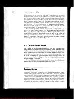
J Ports. Also, many-to-many-to-many relationships are possible
.
Consider the three '
entities Supplier, Part, and Proiect shown in that hgure. A particular part may be sup-i
l plied by several suppliers, depending on the project. Also, the various parts suppliedl
for a specihc project may come from different suppliers. A many-to-many-to-many1
é
1. . relationship is necessary to m odel such a situation accurately. C
I .i
; Entity-relationship modeling is discussed further in the next chapter, which de- ,
5 ib bject-oriented analysis another semiformal technique. The next topic of this 'l !
.
scr es o ,
$ i :
1 ! ë chapter is formal techniques. The underlying theme of the next four seetions is that1 6
employing form al techniques can Iead to more precise specifieations than are possible
,C i .
' 1 with semiformal or informal techniques. However. the use of formal techniques, in ?
'
! l ' eneral
,
requires lengthy training, and software engineers using formal techniques 'i
L
g
! k k need exposure to the relevant mathem atics. The following sections have been written '
; . .
'
; . with the mathematical content kept to a minimum. Furthermore. wherever oossible.
1 't' ' '' ' '
, mathematical formulations are preceded by informal presentations of the same ma-
r terial. Nevertheless, the level of Sections 1 1 .6 through l l .9 is higher than that of the .
i rest of the book
.J
'
jI
1 .
: 1 -
1 j !
i ' j .
i ë !
i
.
'
.
Please purchase Image To PDF Converter on to remove this message, thank you.
! i
i
@ .
n.4 FINITE STATE M ACHINES 335 1
j '
f
'
'
j
'
II.ê FINITK STATE AtHINES i
l
i inally formulated by the 51202 team at the Open i IConsider the following example
,
or g ; jj
University, U.K. (Brady, 1 9771. A safe has a combination lock that can be in one 1!
Iof three positions
,
Iabeled 1 , 2, and 3. The dial can be turned left or right (L or R). lj
Thus, at any time, six dial movements are possible: 1 L, 1 R, 2L, 2R, 3L, and 3R. The 'j'
combination to the safe is 1 L, 3R, 2L; any other dial movement will cause an alarm It
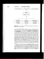
o go off. The situation is depicted in Figure l 1 . l 2. There is one initial state, Safe
' k d If the input is 1 L, then the next state is A. but if any other dial movement, 1 R 1Loc e
.
j
or 3L, say, is made, then the next state is Sound Alarm. one of the two hnal states. I
If the correct combination is chosen, then the sequence of transitions is from Safe 11
Locked to A to B to Safe Unlocked, the other tinal state. Figure 1 l . 12 shows a state I
transition diagram (STD) of a linite state machine. It is not necessary to depict a I
lSTD
graphically', the same information is shown in tabular form in Figure 1 I . l 3. For ; .
each state other than the two final states, the transition to the next state is indicated, :
I
depending on the way the dial is m oved. ( '
ë
! i
; I
è i @ j 'a #aj #tà à i. èè, ., u -,v arf j yjj jj jtjj j -1 k :19 I:qI 14! 1 j i6
,
1/1 l ) . . is tt,sa: A B Safe Unlocked 1i .! @ t
.
t .ê$. o, ,,, .:, ,$ itê : :
any other ( !:
any other dial any other : ;
dial movement movem ent dial movement ' '
: i l
-
b' - l rlitizll E;t E't () ! 1 . 0 j .
' Sq :
sound Alarm yinal state ; ki
i
'
l
Flgvre 11.12 Finite stote machine representation of a combination safe. . 1
)
te
?- Toble ol Nexi S'otes
rd Current state safe locked A B
i
ly Diol movement (
q !1 L A s
ound Alarm sound Alarm ;
ls- 1 R sound Alorm sound Alorm sound Alarm '
,
1
,
at l
2L sound Alarm sound Alarm sofe unlocked rl.l
e
in 2R Sound Alarm Sound Alarm Sound Alorm ! . !
i . 1zs
:n 3L Sound Alarm Sound Alarm Sound Alarm :
: ;
'
e, d Alarm B sound Alorm l i ,aR souna
-
,
I j
lle
iFIgvr@ Xl
.
1a Transition table for a finite state machine.
!
1 '(
'
l
l
l
I
Please purchase Image To PDF Converter on to remove this message, thank you.
' k .
I 1
1
aa* t H A p T z k 41 @ Spetifitojion Phose
'
j
'
:
A finite state machine consists of five parts: a set of states
,
J; a set of inputs,
.
K; the transition function, T, that specihes the next state given the current state and
.
'
.
the cun-ent input; the initial state, S) and the set of linal states, F. In the case of the
.
: combination Iock on the safe:
I 'Th
e set of states J is lsafe Locked, A, B, Safe Unlocked, Sound Alarm ).
The set of inputs K is ( 1 L. 1 R, 2L, 2R, 3L, 3R).I
j The transition function T is depicted in tabular form in Figure 1 1 . 1 3.
The initial state S is Safe Locked.
The set of tinal states F is ( Safe Unlocked, Sound Alarm ) .l
.
l ln more formal terms
, a finite state machine is a s-tuple (J, K, T. S, F), where
,
'
)
I J is a finite, nonempty Set Of States. .
1
r K is a finite, nonempty set of inputs. .
Ii 1 'I- i
s a function from (J x F) x K into J, called the transitionfunaion. ';
'
j'
l q S j is the initial state
.
'
.
! C
.
(
! . F is the set of final states
,
F ç J.
: 1
' i U se of the finite state m achine approach is widespread in computing applications
.
, ii
por example, every menu-driven user interface is an implementation of a finite statei ,
' ; . :1
machine. The display of a m enu corresponds to a state, and enterinc an inout at the
j (
'
'*' *''''' 't
.
.
) i keyboard or selecting an icon with the m ouse is an event that causes the product to
l ) j go into some other state. For example. entering V when the main menu appears on
l $'
j ; the screen might cause a volumetric analysis to be performed on the current data set.
; j . A new menu then appears, and the user may enter G, F, or R. Selecting G causes the
i results of the calculation to be graphed
,
P causes them to be printed, and R causes aI
1 return to the main menu. Each transition has the form
1
1 current slale (menul and eveni goption selectedl =u> nex, stoie (1 1 .1)
.
1 .
' To specify a product
,
a useful extension of FSMS is to add a sixth component1
1 to the preceding s-tuple: a set of predicates, P, where each predicate is a function
j Of the global state, Y, ot the product gKampen, 1 9871. More tormally, the transition
,i function
,
T, is now a funetion from (J x F) x K x P into J. Transition rules now have
.
7
l
.i , the form
'
j7
! t sioge and event and predkofe =:> next sfote (1 1.2) (( turrenl l
.
' ! k i ite state machines are a powerful tbrmalism tbr specifying a product that: ( ) F n
'
i 'F ' can be modeled in terms of states and transitions between states
.
To see how this ?
.
:! formalism works in practice
,
the technique will now be applied to a modified versioni 1
.
E 14 of the so-called elevator problem'
,
see the Just in Case You Wanted to Know box on
l ; 337 tbr background inform ation on the ele
vator problem. :! ! , Page
'
g .!
; .
j ' '
l 11.*.1 Eu vv op Ppoet:M: FINIT: STAT: M v ulxzs
'
j
I
j The problem concerns the logic required to move n elevators between m lloors ac-!
I cording to the tbllowing constraints. '
! j 1 'p
'
1
l ; ' .
i ' !
'
j 1 .
Please purchase Image To PDF Converter on to remove this message, thank you.
i2
ï
'
(
11.* FINITE STATE M ACHINES 33F :
! '
2
S. ëIJ
usT IN ZAS: You W ANTZP To Kwowd I
ktir @ l
.
I
ITh
e elevator problem truly is a classic problem of soft- gineering Notes in the Call for Papers for the Fourth . j
ware engineering. lt first appeared in print in j 968 in the International Workshop on Software Specification and ( j
'Don Knuth's Iandmark book, TheArt 0J' Design (IW SSD, 19861. The elevator problem was one '
.
Ifirst volume ot
Computer Programming, I Knuth, 1 9681. lt is based on of five problems to be used as examples by researchers l
( lthe single elevator in the mathematics building at the in their submissions to the conference
,
held in Mon-
' ia, in May 1 987. In the form in which i lCalifornia Institute of Technology
. The example was terey, Calitorn j
used to illustrate coroutines in the mythical program- it appeared in the Call for Papers, it was termed the l
ming Ianguage MIX. l4t problem and attributed to N. (Neil) Davis of STC- I
IBy the mid
-
l980s. the elevator problem had been IDEC (a division of Standard Telecommunications and !
generalized to n elevators; in addition, specific prop- Cable, in Stevenage, United Kingdoml. ' I
erties of the solution had to be proven, for example, Since then, the problem has attained even wider : jthat an elevator eventually would arrive within a finite prominence and been used to demonstrate an extensive s
time. It was now the problem for researchers working variety of techniques within software engineering in ! '
in the area of formal specilication languages, and any general, not just formal specification languages. It is '
proposed formal specitication language had to work for used in this book to illustrate every technique because,
the elevator problem. as you soon will discover, the problem is by no means . I
The problem attained broader prominence in l 986 as simple as it Iooks. l q
'
. is
.
when it was published in ACM SIGSOFT Sqftware En-
tti '
IC '5
L() k
ln I . Each elevator has a set of m buttons, one tor each floor. These illuminate when . (
'
),t
. pressed and cause the elevator to visit the corresponding lloor. The illum ination
le is canceled when the corresponding tloor is visited by the elevator. i '
!a
2. Each floor, except the first floor and the top floor, has two buttons. one to request !
an up-elevator and one to request a down-elevator. These buttons illuminate w hen
1) pressed. The illumination is canceled when an elevator visits the floor and then :
imoves in the desired direction
.
nt l
3. W hen an elevator has no requests, it remains at its current lloor with its doors 'ln
closed.ln
/e The product now is specitied using an extended finite state machine (Kampen,
'
the n elevators, there l19871. There are two sets of buttons in the problem. In each ot
I
a) is a set of m buttons, one for each floor. Because these n x m buttons are inside Ii
1the elevators
,
they are referred to as elevator buttons. Then, on each floor there are (
at I
two buttons, one to request an up-elevator, one to request a down-elevator. These are ' Ii
s
referred to asjloor buttons. , I
ln l . kThe state transition diagram for an elevator button is shown in Figure 1 l
. 14. Let k
'FI EB(e f) denote the button in elevator e that is pressed to request lloor f. EB(e, f) can 1#
I j
be in two states, with the button on (illuminated) or off. More precisely, the states are '. 'j
iI 1
. EBON(e, f) :
-
ilevator
Buiton (e, f) ON 1. I j(
1 1 .3) . ,EBOFFI
e, f) : klevator Qutton (e, f) OFF ;
If the button is on and the elevator arrives at Eoor f, then the button is turned off. . !c-
l if the button is off and it is pressed, then the button comes on. Thus, two lConverse y
, j
l
'
j
l
; . .
Please purchase Image To PDF Converter on to remove this message, thank you.
l .;
'
i
1
aae < u A p : : R 11 * Spetlfkafion Phose
j '
; ( '
, 1 EBP (e, f )
! EBOFF (e, f ) EBON (e, f )
E EAF (e, f ) '
# l1 ylsu 11
.
1* syD for elevotor button (Kampen,
.
1 987) . (@ 1 987 IEEE .)
)
i
.
j events are involved:
) EBP(e, f) : Ylevator lppon (e, f) zressed
1 EAF(e f) : ilevator e Arrives at jloor f tl 1-4)
f . ?
l To deune the state transition rules connecting these events and states
-
a predicatel
i V(e, f) is needed (a predicate is a condition that is either true or false):
.
f s vte, f): Elevator e is yisiting (stopped at) floor f (1 1.5j
.
! I E
1 1 :'
'
j : Now the formal transition rules can be stated. If elevatorbutton (e, h is off (current
'
1 . tate) and elevator button (e
.
f) is pressed (event) and elevator e is not visiting floor f: k s
? (predicate)
, then the button is turned on. In the format of transition rule ( 1 I .2) this
l 1 becomes(
:
'.
1: jk'
'
EBOFFIe, f) ond EBP(e, f) ond not V(e, f) :::u> EBON(e, f) (11.:)
,
1 J :
'
'
i ' i If the elevator currently is visiting floor f, nothing happens. In Kampen's formalism,. : i
i i 1 events that do not trigger a transition indeed may occur; but if they do, then they are
'
! 1 ! ignored.
j
'
$'
.
*
( 'j Conversely, if the elevator arrives at floor f and the button is on, then it is turned
i off. This is expressed as
1
I EBON(e, f) and EAF(e, f) :z:4. EBOFFIe, f) (1 1.7)1
' Now the lloor buttons are considered
. FB(d, f) denotes the button on tloor f that
l requests an elevator traveling in direction d. The STD for tloor button FB(d: f) is
i hown in Figure 1 1
. 15. M ore precisely, the states are '1 S
l
l FBoxtd. f) : yoor Autton (d, f) ox$
FBoFF(d f) : (loor Autton (d, f) oFF t11-'1' : l
y' '
j! 1
y l k If the button is on and an elevatorarrives at floor f traveling in the correct direction,
' i .
r
j : , d, then the button is turned off. Conversely, if the button is off and it is pressed, then
t 1 the button comes on. Again, two events are involved:
! 7 ( (
p ; r FBP(d, f) : Floor :utton (d, f) ?ressedï i '
.
f '-levotor 1 or
or n Arrives ot yoor f t11-9). !
. . EAFII n, ) :
.ri
:;1 ' N
ote the use of 1 n to denote disjunction. Throughout this section an expression such :!1
( as P (a, 1 n, b) denotes
j
'
'
j P(a# 1 # b) or P(a, 2, b) or . or P(a, n, b) (1 1.10)
1'
j
!l g
! )
1 : :
. à l ':
Please purchase Image To PDF Converter on to remove this message, thank you.
@
'
. l
!'
j 1
.
;
41.* FINITE STATE M ACHINES 33@ :
FBP (d, f ) q;.
.
ilFBOFF (d
,
f ) FBON (d, f ) !: I
EAF (1 n, f) ( 2 j
FI@?e* 11.15 STD for floor button (Kampen, l
1 987) . (@ 1 987 IEEE .) ( j
'
.
I
E I .
; 1
To dehne the state transition rules connecting these events and states, a predicate jS
(d e f), which is delined as follows: Iagain is needed. ln this case, it is , ,
-
41 '
std, e, f): Elevotor e is visitino floor f ond the direction *1
'
in which it is obou-t to move is either 1àte (1 1
.
1 1)
up (d = U), down (d = D), or no requests
are pending (d = N) I
è ;
.
5) Thi
s predicate actually is a state. In fact, the formalism allows both events and states
;
be treated as predicates. i !mt to
'r f Using std, e, f), the formal transition rules then are l
i qAis
FBOFFIH, f) ond FBPId, f) and not S(d, 1 n, f) è i
; ,
E
=,> FBoN(d, f), j( 1 1
.
1 2) . .
.
ô) FBON(d, f) and EAFII n, h ond S(d, 1 n, f) ; j
=u> FBOFFId, f), d = U or D 1
m l
'
,
j
lre That is
,
if the qoor button at floor f for motion in direction d is off and the button is C 1
'
1
pushed and none of the elevators currently is visiting floor f about to move in direction 'j
Cd d hen the lloor button is turned on
. Conversely, if the button is on and at least one 'r . 1 '' t5
elevator anives at Poor f and the elevator is about to move in direction d, then the
button is turned off. The notation 1 n in S(d, 1 n, f) and EAFII n, f) was defined in ' '
.
7)
definition ( 1 l . 10). The predicate V(e, h of definition (1 1 .5) can be defined in terms i '
Aat of S(d, e. f) as follows:
is i
'
V(e, f) = s(U, e, f) or s(D, e, f) or s(N, e, f) (11.la)
.
i
The states of the elevator button and tloor button were straightforward to define.
81 '' ' T
urning to the elevators, complications arise. The state of an elevator essentially L
consists of a num ber of component substates. Kampen identifies several, such as the :
.
7n, elevator slowing and stopping, the dooropening, the dooropen with atimer running, or !
i ::en th
e doorclosing after a timeout gKampen, 19871. He makes the reasonable assumption : .E
'
I
that the elevator controller (the mechanism that directs the motion of the elevator) ! .
initiates a state such as S(d, e, f) and that the controller then moves the elevator 2 I i '
'
j r
I j9) th
rough the substates. Three elevator states can be delined, one of which, S(d, e, t), E
was defined in dehnition (1 l .1 1) but is included here for completeness: ! :
kch )
M(d, e, f): Elevator e is Moving in direction d (floor f is next) i 11 l '
'
'
f Elevator e is >topped (d-bound) af floor f (1 1.14 i ' 's(d
, e, ): y
10) . . w le, f): Elevator e is Waiiing at floor f (door closed) ' ''
1 .
.
l
1
.
I
' j
E
.
Please purchase Image To PDF Converter on to remove this message, thank you.
f
1 .'
'
i
'
j-t
i a*@ t H A p T : R M * Spetilitqlion Phose
i
! These states are shown in Figure 1 1
.
I 6. Note that the three stopped states S(U,i
t e, h, S(N, e, f), and S(D, e, h have been grouped into one larger state to simplify
8 the diagram and reduce the overall number of states.
1
; The events that can trigger state transitions are DC (e, f), the closing of the door
'
1
Of elevator e at floor f; ST(e, f), which occurs when the sensor on the elevator is
6
triggered as it nears floor f and the elevator controller must decide whether to stop
1 he elevator at that floor; and RL
. which occurs whenever an elevator button or a Qoor1 t
1
1
: button is Pressed and enters its OS state.
l DC(e, f): poor çlosed for elevator e, at floor f .
' I sT(e, f): :ensor Jriggered as elevctor e nears floor f (1 1.15)
I RL: Request kogged (buqon pressed)
.
1
'
i These events are indicated in Figure 1 1. 16. '
Finally, the state transition rules for an elevator can be presented. They can bei !
.
.
I ) deduced from Figure 1 l . l 6, but in some cases additional predicates are necessary. To
!
,
'
j be more precise, Figure l 1 . 16 is nondeterministic; among other reasons, the predicates
;
! 6 are necessary to make the STD deterministic
. The interested reader should consult
: j . .)
j (Kampen. 19871 for the complete set of rules; for the sake of brevity, the only rules
! l presented here are those that declare what happens when the door eloses. The elevator
.
'
t (( j moves up
.
down, or enters a wait state, depending on the eurrent state:
k
'
1
.
I stU
,
e, f) and DC(e, f) ::u:> M(U, e, f + 1)
.
j 1 -
) i S(D, e, f) and DC(e, f) =::> M(D, e, f - 1 ) (1 1.1ô)
t
i : ' S(N, e, f) and DC(e, f) rr:::> W (e, f)
i 1 ij
k :
: j
!
'
t
j '
I M ( U , e, f + 1 ) M ( D, e, f )l
l s-r (e, f ) '
t Dc (e, f )
i
j :
! C N r N r - - NRL RL
, l S ( U , e, f ) i.e l S ( N , e, f ) F +1 S ( D , e , f ) I
L -1 u. -! t- -
j' - - - - - - - - - - - . - . - - . . -:
'
:
! l
t I ' DC (e, f ) DC (e, f )
,
j i nt-
.
1 : !(
'
?
'
l . . w (e, f )
! ! RL RL
! ' 1 s'r (e
,
f ) .;
'
1 1
t i ' M (u e
, f) M (o, e, f - 1)l j t ,
i '1
1 r
'
l
.
1 FI@ur* 11.1* STD for elevotor IKompen, 1 987) . (@1 987 IEEE.) .
1;
1
d
'
J
'
.
; .4l
ë
'
i : : .
! :
Please purchase Image To PDF Converter on to remove this message, thank you.
n.y PETRI NzTs a*1
l
The first rule states that, if elevator e is in state S(U, e, f) , that is, stopped at floor f I
labout to go up
,
and the doors close, then the elevator will move up toward the next j .
' floor
.
The second and third l'ules correspond to the cases of the elevator about to go l
.
down or with no requests pending. t ,
The format of these rules reQects the power of finite state m achines for specifying 1
l
complex products. Instead of having to list a complex set of preconditions that have j
to hold for the product to do something and then having to list all the conditions that II
hold after the product has done it, the specitications take the simple form )
'
I )
turreni stcte and evenù ond predicote = next siaùe 1 '
'
l !
'
This type of specification is easy to write, easy to validate. and easy to con- 1 $1
ve14 into a design and into code. ln fact, it is straightforward to construct a CASE t
1 t't
ool that will translate a finite state machine specilication directly into source code. j $
Maintenance is achieved by replay. That is, if new states or events are needed, the I
1
C specitications are modified and a new version of the product generated directly from j
the new specifications. k
i .
.
The FSM approach is more precise than the graphical technique of Gane and i
Sarsen presented in Section 1 1.3. 1, but it is almost as easy to understand. It has a ;
'
drawback, in that for large systems the number of (siofe, evenl, predkoie) triplcs (
can grow rapidly. Also, like Gane and Sarsen's technique, timing considerations are i
'
s formalism . 1not handled in Kampen
These problems can be solved using statecharts, an extension of FSMS gldarel et I
'
al 19901. Statecharts are extremely powerful and are supported by a CASE work- : 1; !
1bench
,
Rhapsody. The approach has been successfully used for a number of large I
real-time systems. 1
hnique that can handle timing issues is Petri nets. ë i i IAnother formal tec'
r
2
: l
' :
:
'
i
' j
I l '.ê
l1.y PETRI N KT: 1
,I'
: j
.
A major difticulty with specifying concurrent systems is coping with timing. This l!)
'
.
'
1
*
.
'
difhculty can manifest itself in many different ways. such as synchronization prob- : j y
lems, race conditions, and deadlock (Silberschatz and Galvin, 19981. Although timing 8 jl '
i /
'
oroblems can arise as a consecluence of a ooor desien or a faultv imolementation, such I j' 't ''' ''' f''-J
'
''' '
t !
'
designs and implementations often are the consequence of poor specihcations. lf spec-
, l à
ifications are not properly drawn up. there is a very real risk that the corresponding 1 j
design and implementation will be inadequate. One powerful technique for specify- i )
q 'ing systems with potential timing problems is Petri nets
.
A further advantage of this ( 1
technique is that it can be used for the design as well. '
'
1
.
Petri nets were invented by Carl Adam Petri (Petri, 19621. Originally of in- j l
terest only to automata theorists, Petri nets have found wide applicability in com- ! ; :
q - I .puter science
,
being used in such fields as performance evaluation, operating system s, : .
-
Iand software engineering
.
In particular, Petri nets have proven useful for describing t
.
!
I L
.
é
'
j u
i i E'
,
l '
Please purchase Image To PDF Converter on to remove this message, thank you.
! l
i
'
i j ,!
'
a*x t u A p T . R ,1 . spetifito.ion phose
1 '
(
'
1
! :2
l ,
t
'
l t .
! 2
1 t ,
j 13 1 1
' pa
j '
. I
( '
l .
J' rx
1 *' 4
,) '
-
1
.
.
1 Flguee 11.17 Petri net.
i 1
i f
'
k
( l concurrent intenrlated activities. But, before the use of Petri nets for specihcations
4 I ;
; 1 can be demonstrated, a brief introduction to Petri nets is given for those readers who
'
; ; : may be unfamiliar with them.l
t A petri net consists of four parts: a set of places
,
P; a set of transitions, T; an input' y
.
t ' ' 1. d t ut function
,
0 . Consider the Petri net shown in Figure l 1.17. '. l : function. , an an ou p
? I. j : rjx
e set of jgaces, P, is tpj g p; g gg t gg j.
.
( l Tj-je set of transitiolàs
s Y, is (t) # tz ) .
1 : -
l k ) The input functions for the two transitions, represented by the arrows from places
! ' to transitions
,
are 91 J
'
' 1 !
'
1 j .
.
I(t1 ) = ( p2, pz )l
,
l l(t2) = .( pa )
,
j The output functions for the two transitions
,
represented by the arrows from1 transitions to olaces
,
are
1 ''' -
1 O(tI ) = lp, J
1 o(t2) = lpa
,
pa )
.
'
l .
1 Note the duplication of pa; there are two arrows from t2 to pa.
l More formally (Peterson, l98 l1, a Petri net structure is a 4-tuple, C =
L I p y 1 o)
.
( , , si l
i 1 p is a finite set of places
. n a: 0.I j . =z l p) , pa, . . . , pn l
.
1 ;
'j ( ! T = ( tl , t2, . . . , tm ) is a finite set of transitions, m k2 0. with P and T disjoint. ' .i
.
l ! l : T > P= is the input function. a mapping from transitions to bags of places.
! I
1' , o : T > Pcxl is the output function, a mapping from transitions to bags of places.
1 f
'
'
.
; t t .
: ) : (A bag, or multiset, is a generalization of a set that allows for multiple instances of
l ! .
i t an element.)
g
1 l M arking a Petri net is the assignment of tokens to that Petri net
.
Figure 1 l .l8 '1
f tokens'. one in pl , two in p2, none in pa, and one in pz. The markingcontains our
; k
'
.
( can be represented by the vector ( 1 , 2- 0, 1 ). Transition t, is enabled (ready to tire), ')
; i
-l I
! l
: ! :1
i ; 1
( .
Please purchase Image To PDF Converter on to remove this message, thank you.
'
.
1 .
:
t
E
II.y PETRI N ETS a*a
92 j
'
@ j
, * 1
ta ( l
'
)
t ' $p 1 1 ,
pa l
@ j
.
I
l
l
I
* Ir)
4 li
!
IFl
guee 11.1* M orked Fetri net. ' l
l
I'
j
ls because there are tokens in p2 and in pa; in general, a transition is enabled if each
of its input places has as many tokens in it as there are ar
-
cs from the place to that
1'o
lt
ransition. lf @1 were to lire, one token would be removed lrom p2 and one from pz, I
at and one new token would be placed in pl . The number of tokens is not conserved-two
.
!
7. tokens are removed, but only one new one is placed in pl . ln Figure l l . l 8, transition q '
l is enabled, because there are tokens in p2. If t2 were to hre, one token would : i it2 a SO
! 4' j
be removed from p2. and two new tokens would be placed in pa. E
Petri nets are nondeterministic', that is, if more than one transition can tire, then l
l
zs any one of them may be fired. Figure l 1 .l8 has marking (1 , 2. 0, 1)'. both tl and :
.
i ,t
2 are enabled. suppose that tl fires. The resulting marking (2, 1 , 0, 0) is shown in !
19 where only t2 is enabled. It tires, the enabling token is removed from ! 1yigure l 1
. s (
o,, and two new tokens are placed in pa. The marking now is (2, 0, 2, O), as shown in ;
' 1 '''' ''
'
' '''-
jFigure l l
.20. 'i
m ' More formally gpeterson, l98 11, a marking, M, of a Petri net, C = (P, T, 1, O),
is a function from the set of places, P, to the set of nonnegative integers'. '
M : P > l 0, 1 , 2, . . . )
.
I
'
A marked Petri net then is a s-tuple (P, T, 1, 0, M). '
An important extension to a Petri net is an inhibitor arc. ln Figure l 1 .2 l , the :
.
inhibitor arc is m arked by a sm all circle rather than an arrowhead. Transition tl is :
=
.
enabled because a token is in pa but no token in pa. ln general, a transition is enabled l I
'
g p
.
if at least one token is on each of its (normal) input arcs and no tokens on any of g 1I
i its inhibitor input arcs. This extension will be used in a Petri net specification of the : I
: : j
7 elevator problem presented in Section l l .6. 1 tGuha, Lang, and Bassiouni, 19871. . 1
.
i
. I
.
! I'
ll.KI Euvv oR pRoetz-: PETRI N zTs I
f ' i :O
.
.
.
I @
Recall that an n elevator system is to be installed in a building with m floors. In $ l
j
'
I 'i 8 thi
s Petri net specitication, each floor in the building is represented by a place, Ff, 1
, i i' 2
jAg ' s f s m
,
in the Petri net; an elevator is represented by a token. A token in Fj denotes
that an elevator is at noor f. 'l:t), q
h ! j
i
.
I .l
1' j
i
.
1
Please purchase Image To PDF Converter on to remove this message, thank you.
'
! k
t -
'
j
'
! 3#* t M A p T : R 41 * Spetlfito#ion Phase
j '
l ;
j '92
l
7 j @
:
k t
.
j ' 2
! p t,
! j : 1
* pa
@
I
l :
5
: .
I . p 4
s
'
i
'
( 1 Flsur. 11.1* Petri net of Figure 1 1 . 1 8 aher firing
; !
.
j tansition tl .
:
;
j '
.
t ! : k1
;t
'
i
'
jj jj .
'
! I :l
: : P 2 '
'
. l'
g: '
! 1 t 21
.
é
I j p j t j
-
( I i
:'( 1 . . p
a j' 1 1 j
@ . (
1 1
.
i i 8
1 I j l
'
j 1 . :I
'
.
'
I$ p
4i
i 1
'
j FI
@vr@ 1I.Q@ Fetri net of Figure 1 1 . 1 9 aier firing1 transition tr
.1
j 'Pa
1 !!
'
Ik
lI
.
j ij . p , t ,
. j 1 :
' j r .t !
1 -
l
: 2 .
l ' '
.
; 1 5 q
'
.
! j . .l i
J / i @9
at
'
' !
.
.
l
( ' ,
5 Flgure 11.Q1 Petri net with an
i i
nhibitor arc.
I
! !l
. 1
t
'
! I
.
I ': i
; ! (
I t .
Please purchase Image To PDF Converter on to remove this message, thank you.
I44
.
y PETRI NETS a*5 I
.
I
1 i
'
Flrs: tlns:reln: Each elevator has a set of m buttons, one for each floor. These $
I ;illum inate when pressed and cause the elevator to visit the corresponding floor
. The j
,;
illumination is canceled when the corresponding floor is visited by the elevator. ; !
I t. To incorporate this into the specihcation
.
additional places are needed. The ele- , ;
vator button for floor f is represented in the Petri net by place EBf, 1 S f :; m. More , ll
t precisely, because there are n elevators. the place should be denoted EBje with 1 :j! l '
1 f s m, 1 s e s n. But, for the sake of simplicity of notation. the subscript e repre- 1
Isenting the elevator is suppressed
. A token in EBf denotes that the elevator button for !
.
lloor f is illuminated. Because the button must be illuminated the first time the button i 'l
ris pressed and subsequent button presses must be ignored
,
this is specified using a I ,
Petri net as shown in Figure 1 l .22. First. suppose that button EBf is not illuminated. ! .
j 'Accordingly
,
no token is in place and, because of the presence of the inhibitor arc, j r
transition EBf pressed is enabled. The button now is pressed. The transition fires and I ): I
a new token is placed in FBf, as shown in Figure l l .22. Now, no matter how many j
times the button is pressed, the combination of the inhibitor arc and the presence of l 9
,
1
: the token means that transition EBf pressed cannot be enabled. Therefore, no more I j
1' th
an one token ever can be in place EBf. Surmose that the elevator is to travel from !
' * ' A *
'
7
floor a to floor f. Because the elevator is at floor o, a token is in place Fa, as shown
'G 'G '*. 'EJ ' )
'
in Figure l l .22. Transition Elevator in action is enabled and hres. The tokens in EBf ' :
and Fg are removed, turning off button EBj, and a new token appears in Ff; the liring I
f this transition brings the elevator from Eoor g to lloor f. jo
This motion from floor g to floor f cannot take place instantaneously. To handle ' IE I
' this and similar issues. such as the physical im possibility for a button to illuminate l '. I
: ' j
at the very instant it is pressed, timing must be added to the Petri net model. That I j
' ) Cis
,
whereas in classical Petri net theory, transitions are instantaneous. in practical j;
situations, such as the elevatorproblem, timed Petri nets gcoolahan and Roussopoulos, ' (
' 119831 are needed to associate a nonzero time with a transition
.
'
j!
I
.
! p
Sellnd tonsooln: Each floor, except the first floor and the top floor, has two I1 :
buttons, one to request an up-elevator and one to request a dow n-elevator. These 1
buttons illuminate w hen pressed. The illumination is canceled w hen an elevator visits 1
the tloor then moves in the desired direction. ; t
I i
'
: ! 2
lEB
f pressed EBf Elevator in action Ff j
1 k@ j
I 'î
I j
! t
I
l:
:
; : lF
g é
. ;
i
'
'
:
: ' I
i
.
q
Flguee 11.QQ Fetri net representation of an elevator button
'
(Guha, Lang, and Bassiouni, 1 987) . (@1 987 IEEE.) 1
!
' 1
l
i ,
'
l : .
i !
! ,
E .
Please purchase Image To PDF Converter on to remove this message, thank you.
l I ':'
.
; '
1r
'
i .
. l a*l t H A p T : R 14 @ spetifiiogion Phose
; , ,
j I FB? pressed FB/ Elevator in action Ffl
. ,
I @
E
i
!
;
,
! 1
.
j '.
'
j '
F@ g
7
:. I
I FBt pressed FBt Ff
.
1
.
j *
i l
1 Elevator in action '
l
It
'
!
'
i i ! Flgue. 1I
.
2a Fetri net representotion of floor buttons ''
.
'
! '
'
.
! $ : gGuha, Lang, and Bassiouni, 1 987j. (@1 987 IEEE.)
! I .
.
! j '
.
J
''
$ t The floor buttons are represented by places FBU and FBd representing the buttons
1 ! f f
! l for requesting up- and down-elevators, respectively. M ore precisely, noor 1 has a
I 1 C u d: t
i button FB) , Poor m has a button FBm, and the intermediate floors each have two
) ! u
.
:
( buttonss FBUf and FB'/ , 1 < f < m. The situation when an elevator reaches lloor f from
.
!
i . floor g with one or both buttons illuminated is shown in Figure 1 1.23. In fact, that
ù ugure needs further refinement, because it both the buttons are illuminated, one is
' turned off on a nondeterministic basis. To ensure that the correct button is turned off '
I requires a Petri net model too complicated to present here; see, for example, (Ghezzi
. 1
I and M andrioli, I 9871. 7
l
I
Thled tonso oln: w hen an elevator has no requests, it remains at its current
floor with its doors closed.1
l This is achieved easily: lf there are no requests
,
no Elevator in action transition! :
: I
is enabled.
1 Not only can Petri nets be used to represent the specifications. they can be used!
! .
( j j . for the design as well (Guha, Lang, and Bassiouni, 19871. Even at this stage of the
' ; development of the product
,
it is clear that Petri nets possess the expressive power) j j
I i i
necessary for specifying the synchronization aspects of concurrent systems
.b 1
.
i !
.
'
i ; !
'
q
j I 'i
:! 1
! i !!
.a z4
'
A formal specitications Ianguage gaining widely in popularity is Z (Spivey, 19921.
'
(For the correct pronunciation of the name Z, see the Just in Case You W anted to
; i . Know box on page 347
.
) Use of Z requires knowledge of set theory, funetions, and
.' 1
1 !
; 1 it f
I i :
Please purchase Image To PDF Converter on to remove this message, thank you.
.
'
i
44.* Z a*y
:
l
'
j
tAs: You w Axn p To Kxow lJusT Ix
l
: ' I
.
IJ
l1 Th
e name Z was given to the formal specification lan- The one totally unacceptable pronunciation is the l
r ) :
'tzee
.
'' The reason is that Z (pro- lguage by its inventor Jean
-
Raymond Abrial in honor American-style, that is,) p
'
'
of the great set theorist Ernst Friedrich Ferdinand Zer- nounced t'zee'') is the name of an American fourth- 1
l I l 87 1-1953)
.
Because it was developed atoxford generation language (see Section 14.2). However, we 1me () (
l'
.
University (Abrial. 1 9801, the name Z is properly pro- cannot trademark a single Ietter of the alphabet. Fur- 1
nounced ''zed,'' the way the British pronounce the 26th thermores we are free to pronounce the Ietter Z the wav I
7
.
''' '* '' *'
1l
etter ot the alphabet. we wish. Neverthelesss within the programming lan- j
Lately, however, moves are afoot to acknowledge guage context, the pronunciation t.zee'' refers to the i
l
that Z is named after a German mathematician and to 4GL, not the formal specification Ianguage. l
ronounce it the German way, Tttzet.'' ln response, Fran- Watch this space tbr the next round in the Z pro- lP
i cophiles and Francophones point out that Abrial is a nunciation wars
. .
1
'
.
j
.
Frenchman and that the letter Z is pronounced ''zed'' in j
French. too. l
l
1
'
1
k '
r
'
1
discrete mathematics, including hrst-order logic. Even for users with the necessary ës
.
background (and this includes most computer science majors), Z initially is difhcult i ja k
to learn because, in addition to the usual set theoretic and logic symbols like R, D, r IO
E 1
and =:>, it uses many unusual special symbols. such as 1, < , F + , and %-+. ! 1n I
lFor insight into how Z is used to specify a product
, the elevator problem of I jtt ? i
.
.
Section l l .6. 1 is considered again. ' js ir
; lf ! l
1 '1
Ti I' 11.*.1 KuvvoR pRoekz-t Z
h ln its sim plest form
,
a Z specification consists of four sections'.
ilt
.
.
; 1. Given sets. data types, and constants.
n ' 2. State definition. ' .
.
1'
I itial state. : 13. n
' jd ,
. 4. Operations. 1
e . I
1
rr Each of these sections is examined in turn. j
1
.
1
- hat is sets that 11
. Glven :e's A Z specification begins with a Iist ot given sets, t . )
! '.
, need not be defined in detail. The names of any such sets appear in brackets. For the , :
ielevator problem
.
the given set will be called Button, the set of al1 buttons. The Z .
,I-
specification therefore begins r
.
'
(;
(Buttonl
1. ' ; I
'
p
l
o : a
. s, e pellnl:lox A z specification consists of a number of schemata. Each l
-
ld
'
.
schema consists of a group of variable declarations together w ith a list of predicates ' j
1
.
j
.
I'
j
Please purchase Image To PDF Converter on to remove this message, thank you.
j . '1
.
1 i
'
t a*a t u A p T : p 11 * spetifitotion Phose
h
'
:
i I
; ,
'
5
.
declorations
1
l l predfcofesj
i :
( '
5 i Flgur. 11.Q4 Formaf of Z schemo &
J' . .
! k
'
. !
i i Button srcge
i
: q floor
-
buhons, elevator
-
buttons :P Bueon
l
.
! l buttons :p Buqon '
i '
' pushed :P Buiton
i
'
ji'
'
( ! è floor buqons o elevator
-
buttons = @* I :
'
.
1 ' . floor buqons u elevofor
- bu:ons - buqons. l ( j
-
1 @
' 1 1
l ' i ' Flgvre 14.25 Z schemc Button
-
state.
5
i 1
1 j . ' '.
l t
:
I 1 .(
j 1 that constrain the possible values of the variables. The format of a schema S is shown'
l l i Fi ure l 1 .24.' n g
1 l
,,
i In the elevator problem
,
there are four subsets of Button: the floor buttons, the
' l t l elevator buttons, buttons (the set of all buttons in the elevator problem), and pushed,1i ;
j i ' the set of those buttons that have been pushed (and therefore are on). Figure 1 1.25
:
! I depicts the schema Button
-
stute. The symbol P denotes the power set (the set of all
1 subsets of a given set). The constraints, that is, the statements below the horizontal line,
!
state that the set of floor buttons and elevotor butions are disioint and that toeether ,
I * - G <# y
E they constitute the set of buqons. (The sets floor
-
buqons and elevator
-
buttons are
1
2 i not needed in what follows'
,
they are included in Figure l 1.25 only to demonstrate
1 he power of Z
.
) ' ':tl
'
'
,
'
1
*
j
'
! :
a. InI:I.I :'l'e The abstract initial state describes the state when the system
. l
i j , first is turned on. The abstract initial state for the elevator problem is1
I E
t ! BuNon
-
lnff & îBu#on
-
sfcfe/ l pushed' = /1
' gj , This is a vertical schema dehnition, as opposed to a horizontal schema dehnitiotb1
J h Fi ure 1 l .25. The vertical schema states that, when the elevator system first! t Suc as g
! ' . is turned on, the set pushed inîtially is empty', that is, alI the buttons are off.1
i I'
l )l ;@
'
! q *
.
@p@m.:I*ns lf a button is pushed for the first time, then that button is turned ,! 1
.
'
' j on. The button is added to the set pushed. This is depicted in Figure l l .26, in which
l operation Pusb 8t/lfon is detined. The ktî in the first line of the schema denotes that '
( this operation changes the state of Button
-
state. The operation has one input variable, .
l button?. As in various other languages (such as CSP (Hoare, 19851), the question marki
l I -
11
.
*
'
'
'
'
''
Please purchase Image To PDF Converter on to remove this message, thank you.
I4.a Z a4@
:
'
-
1
I !
Pusb Btllfon 1 :- (
.
l 2*
h Bvtton
- state 1 ,
I ;b
ueon?: Buqon ; .
'
l .
bueon? e buqonslA è !( $
(ttbutton? 6 pushed) A (pushed' = pushed U lbu:on?)))V lj
(tbuqon? e pushed) A (pushed = pushedll) j
l .:
l 'r
'
' Flgure 11.Q4 Z specification of operation Posb
-
Bvtton. l '.
1 .j
l ù
'
'
t
(?) denotes an input variable, whereas an exclamation mark (!) denotes an output 2 l .l
' variable. I .è
,
The predicate part of an operation consists of a group of preconditions that must ë .
7
.
'
'' - - - - - thold betore the operation is invoked and postconditions that must hold after the opera- 4
'
l #
tion has completed execution. Provided the preconditions are met, the postconditions ' l '.
5 .
1
'
will hold after completing execution. However, if the operation is invoked without k 1 '
g 7ith
e preconditions being satisfied, unspecified (and therefore unpredictable) results ; '
;
.C a n O C C U r . 4
'
b tton? must be a member of EThe first precondition ot Figure 1 l .26 states that u
buttons. the set ()f alI buttons in this elevator svstem. lf the second Drecondition, ,1
' -' *
.
bu:on? g' pushed, is met (that is, if the button is not on), then the set of pushed '
buttons is updated to include button?. ln Z, the new value of a variable is denoted by r k)
t
,
!a prime (')
.
Thus. the postcondition says that, after operation Pusb Bulfon has been ; 1
,
*
.
' ' A - A ''- ; j
ertormed, button? must be added to the set pushed. There is no need to turn on the :i P I
button explicitly', it is sufficient that button? now is an element of pushed. il
.
t
The other possibility is that an already pushed button is pushed again. Because : I
' buqon? (E pushed. the third precondition holdsl and, as required, nothing happens.
r ,
This is indicated by the statement pushed = pushed', the new state of pushed is the
same as the old state. :)
'
I .'
Now suppose an elevator arrives at a floor. If the corresponding lloor button is i 1 1)
'f and similarly for the corresponding elevator button. : l fon
,
then it must be turned ot .
. . l 'Th
at is, if buhon? is an element ot pushed, then it must be removed trom the set, as (
,
1 shown in Figure l 1
.
27. (The symbol à denotes set difference). However, if a button I ri l
is not on. then set pushed is unchanged. i .
,
' ;The solution presented in this section is an oversim plification
,
in that it does not E .
t !distinguish between up and down floor buttons
.
Nevertheless, it gives an indication ,
.
i
,
how Z can be used to specify the behavior of the buttons in the elevator problem. t
t 1 :
; '
'
!
'
jè
'
!l1.@.Q A xAkvsls o: X
i
1 !Z h
as been used successfully in a wide variety of projects, including CASE tools j1
; ' .(Hall
, 1 9901, a real-time kernel (Spivey, l 9901, and an oscilloscope gDelisle and ) . ,t
1
1 r'
I 1 Wifhout the third preconditio ,n the specificafion would not state what is to hoppen if a button already pushed :t
I is puslaed ogain. Tlae results fhen would be unspecified. 'r
,
.
l
q r
j (
! .l
.
Please purchase Image To PDF Converter on to remove this message, thank you.
l
i
!
t a5@ t H A p T K R M @ spetlfito#ion Phose
.j .4 .
t ; Floor Arnva/
l
: A Button State
.
i k) jjon?: Buttonk u
l r buton? e bufonslzq
; (1
.
'
j : (ttbutton? e pushed) A (pushed = pushed X fbuiton?lllv
j (tbutlon? Y pushed) A (pushed' = pushedll)
I :
'
r
Flguee M.QT Z specification of operation Floor
-
Arrival. '
.
! ;
.
' j .'
j Garlan, 19901. Z also has been used to speeify large portions of a release of CICS,!
l the IBM transaction-processing system (Nix and collins
, 19881.i j
(
'
p These successes perhaps are somewhat sumrising, in view of the faet that, evenfor
.
! p ( the simplified version ot the elevator problem, it is clear that Z is not straightforward
1 ' to
use. First is the problem caused by the notation; a new user has to learn the set ofi
i ) :1
.
symbols and their m eanings before being able to read Z specifications
, let alone write
'
'
.
1 . them
.
Second, not every software engineer has the required training in m athematics to '
i 'j r be able to use Z (although recent graduates of almost a11 computer science programs
(. !
'
j I either know enough m athem atics to use Z or could learn what they still need to know
l' l
! with little difficulty).
'
.
l I l z perhaps is the most widely used formal language of its type
.
Why is this,i t
! i and why has Z been so successful
,
especially on large-scale projects? A number ofl
different reasons have been put forward: '
' :
E :
.
i' I . 1
. lt has been found that it is easy to find faults in specihcations written in Z
,1
y especially during inspections of the specifications themselves and inspections
i of designs or code against the formal specihcations (Nix and Collins, 1988.,
uajj, jqqtlj.
j 2. Writing Z specifications requires the specitier to be extremely precise', as a result
j of this need for exactness, there appear to be fewer ambiguities, contradictions,
I and omissions than with informal specifications.j
y' .
' I 3 As a formal language
,
Z allows developers to prove specilications correct when
.
! l : necessary. Thus, although some organizations rarely do any correctness proving2
( f z such proofs have been done
,
even for such practical specifications as thel $ O ,1 '
,
clcs storage manager gwoodcock, 19891.1
. j
i -( I ; 4
. It has been suggested that software professionals with only high-school mathe-
1 : matics can be taught to write Z specifications in a relatively short period of time
.
i
; l H 11 1 990j
.
Clearly such individuals cannot prove the resulting specihcations' ; l a -t
1 j' i to be convct, but then formal specifications do not necessarily have to be proven
I i ( to be correct
.
'
: .
'
,
l .
1 1 5. The useof zhas decreased thecostof software development
.
No doubtmoretimej
' 2
,. has to be spent on the specihcations themselves than when informal techniques
1 ) re used, but the overall time for the complete development process is decreased.a
'
j ; .
( j t 6. The problem that the client cannot understand specifications written in Z has been
l @ . solved in a number of ways
, including rewriting the specifications in naturalI 1
p !
l 1 j
Please purchase Image To PDF Converter on to remove this message, thank you.
.
t
'
1,.* OTHER FoRm L TKHNIQUES asl t!
.
T C.
language. The resulting natural language specifications have been found to be ; ,
I .
clearer than informal specihcations constructed from scratch. (This also was ,
the experience w ith M eyer's English paraphrase of his formal specification for i
' text-processing problem, described in Section l 1 .2. 1 .) 1Naur s
j
I (
The bottom line is that, notwithstanding the arguments to the contrary, Z has I '
t tb
een used successfully in the software industry for a number of large-scale projects. !
Although the vast majority of specifications continue to be written in languages con- I '
siderably less formal than Z, there is a growing global trend toward the use of tormal 1
lspecilications
.
The use of such formal specifications traditionally has been largely a j
ice. However, more and more organizations in the United States are 1,European pract
fications of one sort or another. The extent to which Z and iem ploying formal speci
j
sim ilar languages will be used in the future remains to be seen. !
I
j '
l :
1
i
1
111
.* @ THKR F/RM AL T'QHNIQUES 1
.
.
j ,
Many other formal techniques have been proposed. These techniques are extremely ! k r
ied For example, Anna (Luckham and von Henke, 19851 is a formal specification E''Var . l
language for Ada. Some formal techniques are knowledge based, such as Gist (Balzer, .
5 19851
.
Gist was designed so users could describe processes in a way as close as 21
; l
possible to the way we think about processes. This was to be achieved by formalizing : ; 1
' :
1 1
.
the constructs used in natural languages. In practice, Gist specifications are as hard y1
ito read as most other formal specifications
, so much so that a paraphraser from Gist ; j
f h been written
.
i 2 l (to English as t
1 Vienna dehnition method (VDM) (Jones, 1986b1 is a technique based on denota- , ' j 1
.
.
tional semantics gGordon, 19791. VDM can be applied, notjust to the specifications, 'i 6;
'
'
but also to the design and implementation. VDM has been used successfully in a g !
number of projects, most spectacularly in the Dansk Datamatik Center development i
2
of the DDC Ada compiler system (Oest. 1 9861. 1
'f t way of Iooking at specifications is to view them in term s of sequences i' A dit eren
t'
j. of events
,
where an event is either a simple action or a communication that transfers , l
data into or out of the system. For example, in the elevator problem. one event consists ! l
'
h levator button for floor f on elevator e and its resulting illumination. ' 'of pushing t e e
Another event is elevator e leaving lloor f in the downward direction and the canceling ;'
'
.
1
of the illumination of the corresponding floor button. The language Com m unicating 1
ibing lSequential Processes (CSP)
,
invented by Hoare, is based on the idea of descr :
the behavior of a system in terms of such events gldoare, 19851. In CSP, a process is ! ;1
:
. described in terms ofthe sequences of events in which the process will engage with its 1
environment. Processes interact with each other by sending m essages to one another. !
.
'
'r
q
CSP allows processes to be combined in a wide variety ol ways, such as sequentially, 'j
in parallel. or interleaved nondeterministically. . ' j
2 iThe power of CSP lies in the executable nature of CSP specifications (Delisle and I
'
il -@Sch
wartz, 19871., as a result, they can be checked for internal consistency. In addition, I j
CSP provides a fram ework for going from specifications to design to im plementation ' '!
in a sequence of steps that preserve validity. In other words, if the specihcations are
( '
' j j
.
; I
Please purchase Image To PDF Converter on to remove this message, thank you.
1 -! ! :
'; 1 .
I l
: 1 ) i asa e H A p T z R .4 * speeificofion phose'
'
j
'
'
!
1 '
.
.
1 1
: l $ ! correet and the transformations are performed correctly, then the design and imple-
p
! ' ' mentation will be con-ect as well
. Going from design to implementation is particularly
'
'
l l straightforward if the implementation language is Ada.;
'
: , t
'
2 j' However, CSP also has its disadvantages. ln particulaq like Z, it is not an easy
l language to learn. An attem pt was made to include a CSP specilication for the elevator
2
.
.
( problem gschwartz and Delisle, 19871 in this book. But the quantity of essential
' prelim inary m aterial and the Ievel of detail of explanation needed to describe each
2
l Csp statement adequately were simply too great to permit inclusion in a book as
.
:
l :
( general as this one. The relationship between the power of a specification language
and its degree of difficulty of use is expanded in the next section.;
-
'
l J .
( k :
:
'
.
.
l
j ''
2 11.1* Z@M PARI:@N @F SPEQIFIZATI@N
1 1 yutuxjq uus ,: i
l Ii
! i !
'
. .
.
1 . The main lesson of this chapter is that every development organization has to decide
l ' : hat type of speeification language is appropriate for the product about to be devel-1 Wi
1. E oped
. An informal technique is easy to learn but lacks the power of a semiformal or
!
1
1
1 formal technique
. Conversely, each formal technique supports a variety of features
' J that may include executability, convctness proving. ortransformability to design and1
, 51 ' i
mplementation through a series of correctness-preserving steps. Although generallyt
'
'
:
6 1 the more formal is the technique the greater its power
,
formal techniques can be dif-k
'
1 1 (
'
1
1 k : ticult to learn and use. Alsos a formal specification can be difhcult for the client to
i 1 ' d
erstand. In other words, there is a trade-off between ease of use and the power of( un
.
q a specitication language.
j In some circumstances, the choice of specification language type is easy. For ex-
ample, if the vast majority of the members of the development team have no training inl
l computerscience. then itis virtually impossible to use anything otherthan an informal
I iformal specification technique. Conversely, where a mission-critical real-timeor sem
'
L
'
i system is being built in a research laboratory, the power of a formal specitication
' technique almost certainly will be required.J
t . : An additional com plicating factor is that many of the newer formal techniques
h i i have not been tested under practical conditions
. Considerable risk is involved in usingI !
,
1 1 ; such a technique. Large sums of money are needed to pay for training the relevant
mem,'l 1 ' bers of the development team, and more money will be spent while the team
f t ' adiusts from usinc the lanxuage in the classroom to using it on the actual project.
l . ! -' '-' '-',
T l Furthermore, the language s supporting software tools might not work properly, as
j '1 ' happened with SREM (Scheffer
, Stone, and Rzepka, 1 9851, resulting in additional1 1
.1 ù ) expense and time slippage. But if everything works and the software project man-1
l agement plan takes into account the additional time and money needed w hen a new!
j l!
1 technology is used on a nontrivial project for the first time, huge gains are possible.i
I which specification technique should be used for a specific project? lt dependsi
'
l on the project, the development team, the management team, and myriad otherfactors,
l such as the client insisting that a specific method be used (or not used)
. As with so;
'
.
i I
j '1
.
i l '
I ! i
Jl ? f
Please purchase Image To PDF Converter on to remove this message, thank you.
! .
14.41 TESTINO ouRlNo TH: 5pEcIFIcATIoN PHASE asa
l
' 5 etifitodion Me#hod Coiegory strengghs Weaknesses l )) P 1
. . .
j '
' '
p $
Natural Ianguage (Section i 1 .2) Informal Easy to Iearn Imprecise 'i ô
! j .'gE
osy to use Specifications can II
for client to understand 6e ambiguous, p
.
Easy
contradictory, and/or . I i
incomplete 1 1
I
Entifprelotionship modeling Semiformal Can be understood by client Not as precise os formal
.
l )
! 2
y
.
(Section J 1 .5) More precise than informal methods j 4
FSL/FSA (Seciion 1 1 .:) methods Generally cannot handle ij S'
SADT (section 1 1 .z.) timins ( '.
j 5.SZEM (Section 1 1
.
:) : I '
: I )tStructured systems analysis )
1(Section 1 1
.
3) li i
.
j '!
.
Annc (Section 1 1 .9) Formal Extremely precise Hard for tecm to Iearn ; j ,t
CSF (Section 1 1 .9) Can reduce specification Hard to use ; i .
faults Almost impossible for most 'Extended finite state machines
(Section 1 1 .é) Can reduce development clients to understand
Gist (Section 1 1 .9) COst and effort : j;
.
!Can support correctnessFetri nets (Section 1 1
.
Z) :.
provjng .
j' VDM (S
ection 1 1 .9) !i
z (section 1 1 .8) . ! I
'
2 (
'
t
i Flguee 11.Q@ Summary of the specificatîon methods discussed in this chapter and the section in which each is described
.
l
' j 1
'
.
j
many other aspects of software engineering, trade-offs have to be m ade. Unfortunately,
there is no simple rule for deciding which specification technique to use. 1
'
Figure 1 l .28 is a summary of the ideas of this section. . I :
.
j .' !
.: .
' j
l
.
.
q i
p :
'
11.11 T::TING PURIN/ TH: SPEQIFItATI@N PHM : y ;
' j1
E iDuring the specilication phase
,
the functionality of the proposed product is expressed ;
in the specihcation document. It is vital to verify that the specification l 1
.precisely
.
I
document is correct. One way to do this is by means ofa walkthrough of the document 1
(Section 6.2. l).
A m ore powerful mechanism for detecting faults in specihcation documents is i
inspection (Section 6.2.3). A team of inspectors reviews the specihcations against 1 ! E 1 'an
!a checklist
. Typical items on a specihcation inspection checklist include these: Have
'
; (th
e required hardware resources been specihed? Have the acceptance criteria been 1i
!specitied?
! ,
. !:
:
j ' y
Please purchase Image To PDF Converter on to remove this message, thank you.
1 1
; k I ' :
!t
'
'
'
j
'
è l ' as* e u a e T : p ,1 . spetifitofion phoset
'
,
'
1 l
I :
( 1p ) lnspections were suggested lirst by Fagan in the context of testin/ the desijm and
.
j ' . ''''' *'''' .the code (Fagan
,
19761. Fagan's work is described in detail in Section 6.2.3. However,E
'
:
1
,
'
inspections also have proven to be of considerable use in the testing of specifications
.
( For example. Doolan used inspections to validate the specifications of a product that,'
.
l :
I j when built, consisted of over 2 million lines of FORTRAN gDoolan, 19921. From data
'
.
ù : on the cost of fixing faults in the product, he could deduee that each hour invested in ':
J inspections saved 30 hours of execution-based fault detection and correction.è
l w hen a specihcation has been drawn up using a formal technique
,
other testing1
.
! techniques can be applied. For example, correctness proving methods (Section 6.5)
:
can be employed. Even if formal proofs are not performed, informal proof techniques: i j
( j ) such as those used in Seetion 6.5.1 ean be an extremely useful way of highlighting
' 1 ification faults
. ln fact, the product and its proof should be developed in parallel
.
l I SPCC
i j In this way, faults are detected quickly.
.
I(
! .:l i
.
I ! :
I 1 i
' i 41 12 tA :K Tooks FoR Tu: gpKtlyltv lox1 j ' @
'
j
I I PHAS:; j (
:
.
j' , .1 I Two classes of CASE tools are particularly helpful during the specification phase
.
The ''
f l .
I t , first is a graphical tool. W hether a product is represented using data flow diagrams,
1 i è petri nets
,
entity-relationship diagrams, or any of the many other representationsj 1
j t t omitted from this book simply for reasons of space, drawing the entire product l)y!
j ; hand is a lengthy process. In addition, m aking substantial changes can result in having
2 ( to redraw everything from scratch. A drawing tool therefore is a great time saver. Tools
1 of this type exist for the specihcation techniques described in this chapter, as well as
j many other graphical representations for specifications. A second tool needed during '
: this phase is a data dictionary. As mentioned in Section 5
.4, this tool stores the name ';
.
; and representation (format) of every component of every data item in the product,
L j j including data flows and their components, data stores and their com ponents
,
and '
) J processes (actions) and their internal variables. (Figure l l .5 shows typical information
t 1 that would be stored in a data dictionary for Sally's Software Shop
.
) Again, a wide
' !
'
1
.
; T j selection of data dictionaries run on a variety of hardware
.
1 what really is needed is not a separate graphical tool and a separate data dic-
l ! tionary. Instead. the two tools should be integrated, so that any change made to a
-
j
.
data component is reflected automatically in the corresponding part of the specifica-( tion
. Among the m any exam ples of this type of tool are Analyst/Designer
,
Software)
'
4 ,j . through Pictures, and System Architect. Furthermore. many such tools also incorpo-
l 1 ' rate an automatic consistency checker that ensures consistency between the specih
-l II j
; cation document and the corresponding design document. For example, it is possiàle
:) , j to check that every item in the specilication document is canied forward to the design .
'
1 1 document and that everything m entioned i
n the design has been declared in the dataL 2 i
'
:
; j I dictionary.
' p
' !
:
A specification teehnique is unlikely to receive w idespread aeceptance unless a ,
l
! tool-rich CASE environment supports that technique. For example, SREM (Section ,(
1 1 4) probably would be used far more widely today had REVS. its associated CASEi l l ; ' .
.
I j .I
' r :
1 : .)
.
Please purchase Image To PDF Converter on to remove this message, thank you.
'
j
14.4* A1R GOURMET CASE STUDY: STRUCTURED SYSTEMS ANALYSIS 3S5 1
! j
nd tool set
,
performed better in the U.S. Air Force tests gschefter, Stone, and Rzepka, t .
er, l 9851. lt is not easy to specify a system correctly, even for experienced software !! 1
.
RS. professionals. lt is only reasonable to provide specifiers with a set of state-of-the-art I y
at. CASE tools to assist them in every way possible. I
I
lta I
iin ;
I
I
ng i
I t5) ll
.Ia ETRItS F@R THE SPEtIFIQATI@N PHASK l i
les ) j
ng As in al1 other phases, during the specihcation phase it is necessary to measure the ! j
el. five fundamental metrics'. size, cost, duration, effort, and quality. One measure ot the j
'
'
i
r
size of a specihcation is the number of pages in the specihcation document. If the j .ë
same technique is used for specifying a number of similar products, then differences !
in specihcation size may be signiticant predictors of the effort needed to build the j
lvarious products
.
j j
Turning to quality, a vital aspect of specihcation inspections is the record of fault 1
statistics. Noting the number of faults of each type found during an inspection is an
integral part of the inspection process. Also, the rate at w hich faults are detected can
give a measure of the efficiency of the inspection process.
'he Metrics for predicting the size ofthe target product include the number of items in
the data dictionary. Several diftkrent counts should be taken, including the number ofEIS
,
hles, data items, processes (actions). and so on. This information can give management I,ns
I Ib
y aprelim inary estimate regarding the effort required to build the product. It is im portant I
to note that this information is tentative at best. After all, during the design phase, a !ng I
a1s process in a DFD may be broken down into a number of different modules. Conversely, I
i
as a num ber of processes together may constitute a single module. Nevertheless, metrics :
derived from the data dictionary can give management an early clue as to the eventual 'ng
aae size of the target product. !
!
.ct, . q
d )n
)
On j )Ld
e , 1 tl11
.
14 A IR G O URM ET QAS: STupY: STRUW UREP l :
.
i (ic
.
sysTzM s A xAkysls I
i J) a t
j
2a- As a consequence of careful interviews followed by the building of a rapid prototype I jl
àre in the requirements phase, the Gane and Sarsen structured systems analysis process i i
j Ai
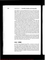
)o- was relatively straighttorward to perform. The final data flow diagram is shown in l
i
ifi- Figure l l .29.
nle The pivotal component of the DFD is the SPECIAL MEAL DATA store of data j
gn (the open rectangle in the center of Figure l l .29). The data for the store are obtained 2
'
jàta from three sources: the onboard meal reports scanned by the FLIGHT AU ENDANTS ! ,
(top Iettl', the store of RESERVATIO N DATA (top centerl; and the scanned postcards
1
s a containing the meal appraisals of the PASSENGERS (top right). Specihc special mecl . ) ,
on details from the SPECIAL MEAL DATA store of data are utilized to generate the six ' i
TE reports by the processes represented by the row of six rounded rectangles in the lower : j
' r g
i 1
i E.
I
Please purchase Image To PDF Converter on to remove this message, thank you.
l l
i I
;
; a54 t H A p T : R 11 @ spetifitolion Phase1
1
.
J 'ë
'
11
generalI enter'
i reservationreservation
i details
I j '' I
. . eneral!
r . reservation
: ; I details
î i l FLIGHT
t PASSENGERl
.
ATTENDANTS; g
'
( RESERVATIONi
i DATA) -
ë '! .
! j meals special special passenger
1 reservationt Ioaded meals meabs meal
details! r details details details appraisal
.
j ' kI
j l èq extracti
j
j complete and generate snecial generate scanscan onboard onboard r- and mail
( ! . meal postcards
$ ! report report postcards
' ! j i requests
. ; . I ,i
I ; reservation1 meals special spe
cial passenger1 details
i Ioaded meals meals meal$ 1 delails details details appraisal
.
4
!
1 l . 1 x c l
I i ;
. spEcIAL MEALI 1 :
' t 1 DATAi
-
I h '
'
l ' ial special special special. 1 special special spec
1 I meals meals meals meals meals meals
j i
! I details details details details details details
: I
r :
generate generate generate generate generate generate
; caterer percentages not Ioaded onboard poor-quality Iow-sodium
: I report report report reoort renort reoort
'
i I ' ' ' ,
.
, ! ji .i 1
slart start percent- start no1 start On- starl poor- start Iow-1
l catererg and and ages and Ioaded and board and quality and sodi
uml ! . end report end report end report end report end report end report' 1
detailsj j ) date date details date details date details date details date details
! j ! ) ) '
1 ' j1
1 I . >
l i : AIR GOURMET CUSTOMER LOW-
l l CATERER nEuvloss sooluuMANAGEMENTi
DEPARTMENT CATERERl .
j '
;
i FI uee 11
.
2* Data flow diagram for Air Gourmet product.l 1 *
I 1 :
'
i . gl
!
'
j l
.
.
) *1
Please purchase Image To PDF Converter on to remove this message, thank you.
l
! '
Mas AIk GOURMET CM E STUDY: SOFTWARE PROJECT M ANAGEMENT PG N 357 l 1
4 .
halfof Figure 1 l .29. To generate a report. the start ond end dote of that report must )
.
!
be supplied by the recipient of the report (the recipients are represented by the row
of four double boxes at the bottom of Figure l 1 .29).
The data flow diagram was constructed by exam ining the flow of data. First, each !
report in turn was considered. The input to a report consists of two parts: special '
meal details and sfart and end date. The special meol details come from the store k ',
of SPECIAL MEAL DATA, and the start and end dates are supplied by the recipients l .l
. of the respective reports. Therefore, the bottom half of Figure l l .29 was constructed !
by analyzing the input data for each report and the destination of each report. i '
I
The sources of the SPECIAL M EAL DATA were analyzed', this part of the flow of i )
h lf of Figure 1 l .29. The first step in acquiring spe- l
jdata was used to construct the top a
cial meal data is to get the relevant reservation details. This information is provided l
1 .b
y the FASSENG ER (top right corner of Figure l l .29) to process enter reservation j
and stored in RESERVAIIO N DATA (the data store in the middle of the top half of !1
Figure 1 1.29). proeess extroct special meal requests was then added to the DFD to $
'
SFECIAL M EAL DATA i
'
transter the relevant details to .
:
Next, the onboard data were considered. Each onboard report has to be generated
for the FLIGHT AU ENDANT, then the FLIGHT AU ENDANT completes and scans j
.
('
that report. This flow of data was modeled by the boxes and labeled arrows in the ï ! e
l ft corner of Figure l l .29. As betbre, this portion of the data flow diagram was ' ' j j'top e
constructed by considering the relevant flow of data. its source and destination, and j
the processes that transfbrm it. ! 1
The mailing, returning, and scanning of the postcards was handled similarly. Each i i I 't'
: t t .postcard is generated using data in SPECIAL MEAL DATA and sent to the relevant
: i 4
FASSENGER, who fills it in and returns it. This loop of data flow was modeled by l 11
the boxes and labeled arrows in the top right-hand corner of Figure 1 1.29. A gain, f j
once the source and destination of this flow of data were identihed and the relevant l )
processes determ ined, adding this data flow to the DFD was straightforward. This 't
l ted the data flow diagram of Figure 1 l .29. ' 1comp e
The remainder of the structured systems analysis appears in Appendix E. The ;1
organization and presentation of the material in Appendix E is such that the client !
rapidly can understand exactly what is going to be built. However, a major factor in
,
'''' '' I
achieving that understanding is that the client was able to experiment w ith the rapid
prototype during the requirements phase.
:
.
)
'
l
l:
j
11.15 A IR G O URM KT ZASK STUPT: S@F ARE l f$
'
!P R/JKtT ANAGEM ENT P. AN :1 '
.
'
(
' jNow that the speeifications are complete
,
the software project management plan i
(SPMP) is drawn up, including estimates of cost and duration (see Chapter 9). Ap- 1t
Cndix F Contains a Software project management Plan (SPMP) for development of 1 )P
the Air Gourmet product by a small (three-person) software organization. This plan i
hts the IEEE SPM P format (Section 9.5). y
5
ii
Please purchase Image To PDF Converter on to remove this message, thank you.
j '1
.
)
l
) a5* < H A p ' : * 11 * Spetifoolion Phose
1
l
i
11.1* CHALLEN/ ES @F THK SPEtIFItATI@N PHA:K
I I ' .
' A repeated theme of this chapter is that a specification document m ust be simul-
.
'
'l I i, taneously informal enough for the client to understand and formal enough for the
.
.,
' j
.
; development team to use as the sole description of the product to be built. A major
t challenge of the specihcation phase is to resolve this contradiction. There are no easy
i answers. On the contrary, a permanent conflict lies between the two competing ob- '
i
.
k i jectives, and the development team must simply do its best to steer safely between )i
'
i scylla and Charybdis
.i
'
p I A second challenge of the specitication phase is that the boundary line between ,
j I specifications (''what'') and design (''how'') is all too easy to cross. The speciscation
1 ri document should describe what the product must do', it mustnever say how theproduct
.
l j is to do it. For example, suppose that the client requires a response time of no morei
rj : than 0.05 seconds whenever a certain network routing computation is performed. The
; : specihcation document should state exactly this and nothing more. In particular,:
1 1 l the specification document should not state which algorithm must be used to achieve
I ' ' ime
.
That is, a specification document has to list all constraints, but it 7h
: this response t7
! ' ' must never state how those constraints are to be achieved
.i 1 i Another example of this potential pitfall arises from data flow diagrams (Section1
.
l 1 l 3 l)
.
A box with rounded ends denotes a process (actionl; it does not denote a' l i - . .
'
j ( , module. As explained in Section l l . l 3, a process in a DFD may be broken down .
'
i ) into a number of different modules and, conversely, a ntlmber of processes may be
.
) , ': combined into a single module. The key point is that this rehnement of processes
l!1 I l into modules must take place during the design phase
,
not the specihcation phase.
'
1 1 The specification document has to describe the actions of the target process. It mustl '
i '' never specify how those actions are to be implemented
,
not even the modules to which '
! each is assigned. The design team's task is to study the specilication as a whole and
1 li decide on a design that will result in an optimal implementation of that specihcation;
.
. l I this is described in chapter l 3
.
Until the product as a whole has been decomposed1
ji into modules
,
it is premature to try to assign actions to specific modules; the result is 'I: i
1 almost certain to be suboptimal.l I
I j ' .1
;
j : . :I
: !l t . '
.
ï
I i ZHAPTKR Revlzw 'I 2
I q
'j ' ;
! 1 g specitications (section l 1.1) can be expressed informally (Section 1 1.2), semifor-:1
i ' l I 3 through l I
.
5). or formally (Sections l l .6 through 1 I .9). :mally (Sections .
'
1 1 The major theme of this chapter is that informal techniques are easy to use but .i E
1 l ' imprecise'
, this is demonstrated by an example (Section 1 1 .2.1). Conversely, formal!
-
!
j j techniques are powerful but require a nontrivial investment in training time (Section
l l l . 10). One semiformal technique, Gane and Sarsen's stnlctured systems analysis, is '' jk
'
j .! ! d
escribed in some detail (section l l .3). Formal techniques described include unite: I r
j .l j . state machines (Section l 1 .6), Petri nets (Section 1 l .7), and Z (Section l 1 .8). Material
'
l 1 ' on specification reviews appears in section l l . I l . Next follows a description of CASE '
I j
'
i .
.l ;
1 ii
.
'
(
'
Please purchase Image To PDF Converter on to remove this message, thank you.