Advances in Steel Structures - part 8 potx
Bạn đang xem bản rút gọn của tài liệu. Xem và tải ngay bản đầy đủ của tài liệu tại đây (694.38 KB, 10 trang )
50
J.M. Rotter
described derive from large displacements; small displacement ideas and small displacement analysis
lead to serious misinterpretation of both test results and appropriate design measures.
Under fire loading, the dominant phenomenon in
determinate
structures is
material degradation.
In
highly redundant
structures, the single most important factor is the effect of
thermal expansion.
Where
this leads to high stresses, damage occurs to the material (plasticity or concrete cracking). Where
instead, large displacements develop in a post-buckling mode, the expansion is accommodated without
so much damage, loads are carried by membrane action and the performance is considerably improved.
Large displacements are commonly associated with bending failures, but here they may be beneficial,
occurring with membrane thrusts, or with membrane tensions, depending on the thermal regime. A
key conclusion is that the design criteria must not be based on limitation of deflections during the fire.
The effects of high temperatures on structures are best interpreted in the context of Eqns 2-4, which
permit the roles of expansion and material degradation to be properly identified and which decouple
the displacement and stress fields. Thermal expansion often couples with large displacements to
produce effects which appear counter-intuitive to the conventionally trained structural engineer.
These findings are of fundamental importance to our understanding of composite frames in fire. They
have major implications for the development of design philosophies and procedures.
ACKNOWLEDGEMENTS
The support of DETR for funding this research through the PIT scheme is gratefully acknowledged.
The author is most grateful for many discussions and calculations provided by Dr Asif Usmani and Dr
Abdel Sanad of Edinburgh University and Dr Mark O'Connor and Dr Xiu Feng of British Steel.
REFERENCES
1. ABAQUS (1997) "Abaqus Theory Manual and Users Manual", Version 5.7, Hibbit, Karlsson and
Sorensen Inc., Pawtucket, Rhode Island, U.S.A.
2. Euler, L. (1744) "Methodus inveniendi lineas curvas maximi minimive proprietate gaudentes, sive
solutio problematis isoperimetrici latissimo sensu accepti", Lausanne & Geneva, Reprinted 1952
in Leonhardt Euleri Opera Omnia, Series 1, Vol. 24, Bern.
3. ENV 1994-1-2 (1995) "Design of Composite Steel and Concrete Structures: Structural Fire
Design", Eurocode 4 Part 1.2, CEN, Brussels.
4. Kirby, B.R. (1997) "British steel technical European fire test programme - Design, construction
and results", in Fire, Static and Dynamic Tests of Building Structures, eds G.S.T. Armer and T.
O'Dell, Spon, London, ppl 11-126.
5. Martin. D,M. (1995) "The behaviour of a multi-storey steel frame building subject to natural
fires", British Steel Technical Report No. 2.
6. Moore, D.B. (1997) "Full scale fire tests on complete buildings", in Fire, Static and Dynamic
Tests of Building Structures, eds G.S.T. Armer and T. O'Dell, Spon, London, pp3-15.
7. Newman, G.M. (1997) "Design implications of the Cardington fire research programme", in Fire,
Static and Dynamic Tests of Building Structures, eds G. Armer and T. O'Dell, Spon, pp 161-168.
8. Rotter, J.M., Sanad, A.M., Usmani, A.S. and Gillie, M. (1999) "Structural performance of
redundant structures under local fires" Proc., Interflam '99,8th Int. Fire Science and Engg Conf.,
Edinburgh, 29 June- 1 July, Vol. 2, pp 1069-1080.
9. Sanad, A.M., Rotter, J.M., Usmani, A.S. and O'Connor, M.A. (1999) "Finite element modelling
of fire tests on the Cardington composite building" Proc., Interflam '99,8th Int. Fire Science and
Engg Conf., Edinburgh, 29 June - 1 July, Vol. 2, pp 1045-1056.
Design Formulas for Stability Analysis
of Reticulated Shells
S. Z. Shen
Harbin University of Civil Engineering and Architecture
202 Haihe Road, Harbin 150090, China
ABSTRACT
The aim of the paper is to propose some kind of design formulas for stability analysis of single-layer
reticulated shells, reflecting the recent advances in theoretical study but simple in form for the
convenience of practical application. For this purpose a comprehensive parametrical analysis of
stability behaviors of single-layer reticulated shells of different types with various geometric and
structural parameters has been carried out based upon complete load-deflection response analysis
with consideration of the effects of initial imperfections and unsymmetrical distribution of loads
More than 2800 examples of reticulated shells of prototype were analyzed, and the plentiful results
obtained were thoroughly studied. As a result, practical formulas for predicting limit loads of
reticulated domes, reticulated vaults with different supporting conditions, as well as reticulated
shallow shells, obtained by regression analysis, were proposed.
KEYWORDS
Stability analysis, Complete load-deflection analysis, Limit load, Design formula, Reticulated shells,
Reticulated domes, Reticulated vaults, Reticulated shallow shells, Reticulated saddle shells
INTRODUCTION
The stability analysis is known as the key problem for the design of reticulated shells. The stability
character of a complicated structure with numerous degrees of freedom such like reticulated shells
can be revealed clearly and accurately by complete load-deflection response analysis, in which the
51
52
S.Z. Shen
structural response under loading is regarded as a continuous process rather than some individual
structural properties such as critical load, buckling mode and etc The complete load-deflection
curves give a more perfect picture about the behaviors of the structure. The deformation shapes
varying with the loading process, and the possible buckling of different orders and of different
characters (over-all or local buckling, bifurcation or limit point), with the corresponding critical loads
and buckling modes, can be revealed in their proper order by the complete-process analysis. With the
development of non-linear finite element analysis and methods for tracing equilibrium path, it can be
said that the problem of stability evaluation of reticulated shells on the basis of complete load-
deflection response analysis has been well solved from the viewpoint of theoretical side.
However, engineers working in design practice still feel puzzled when dealing with stability
problems of reticulated shells. The theoretical method as discussed above seems to them too
complicated for direct application. So it's desirable to propose some kind of design formulas,
reflecting the recent advances of theoretical study but simple in form for the convenience of practical
application. For this purpose a comprehensive parametric analysis of stability behaviors of different
types of single-layer reticulated shells with varying geometric and structural parameters has been
carried out based upon complete load-deflection analysis with consideration of the effects of initial
geometric imperfections and unsymmetrical distribution of loads. The "Consistent Mode Method" is
proposed for the imperfection analysis. This method assumes the geometric imperfection of a
reticulated shell to be distributed in consistence with the buckling mode of first order of the structure,
which is supposed to be very likely the most unfavorable for the expected limit load of the reticulated
shell. More than 2800 examples of reticulated shells of prototype were analyzed, and the plentiful
results obtained were thoroughly studied. As a result, practical formulas for predicting limit loads,
obtained by regression analysis respectively for different types of reticulated shells, rather simple for
application but based upon accurate theoretical procedure as described, were proposed.
The complete-process analysis was carried out on the basis of geometrically non-linear finite element
method, without consideration of material non-linearity, because it would be too time-consuming and
hence very difficult at present to carry out such a large-scale parametric analysis with consideration
of both geometric and material non-linearity. Besides, the reticulated shells under service condition
are working in elastic range, and the material non-linearity would lead to some decrease of safety
reserve in load-capacity of the structure; the latter effect could be assessed by some independent
study [Wang]. A special computer program for complete load-deflection response analysis of
complicated structures based upon non-linear finite element method, compiled by the author's team,
was used for the parametric analysis and was proved to be effective.
THE PLAN OF PARAMETRIC ANALYSIS
The parametric analysis was carried out for single-layer reticulated domes, vaults, elliptical
paraboloid shells ( EP shells, or shallow shells ) and hyperbolic paraboloid shells ( HP shells, or
saddle shells ). For the purpose of practical application, all the reticulated shells analyzed are of
prototype with member sections determined by calculation as in practical design. As the usual case in
China, circular steel tube members and welded hollow spherical joints are used for these structures.
Design Formulas for Stability Analysis of Reticulated Shells
53
The reticulated domes analyzed have net systems of Kiewitt type ( K8 and K6 ), Schwedler type and
geodesic type. For the Kiewitt dome K8, which was taken as the typical system to be studied, four
different spans ( L = 40, 50, 60 and 70m ) and four different raise-span ratios ( f/L = 1/5, 1/6, 1/7 and
1/8 ) with four sets of member sections for each size, i.e. 64 different domes were analyzed. The
effects of initial imperfections of consistent mode and with a maximum value equal to L/1000 were
analyzed for each of the domes; besides, for part of the domes the effects of imperfections with
different values from L/1000 to L/100 were systematically studied. It's assumed that the dead load
( g ) is uniformly distributed over full span, while the live load ( p ) could also be distributed over
half-span (uniformly as well ); three different ratios of live load to dead load were considered: p/g =
0, 1/4 and 1/2. According to this plan, near 500 examples of K8 domes were analyzed, and, if
including the similar study for K6 domes, Schwedler domes and geodesic domes, the non-linear
complete-process analysis was carried out for 840 reticulated domes.
The reticulated vaults might have three kinds of supporting conditions: supported along the boundary,
supported along two longitudinal edges, or supported at two end cross-sections by means of rigid
diaphragms. The triangular net system, consisting of longitudinal and two sets of diagonal members,
as the most popular one is assumed for the reticulated vaults. The ratio of length to wave-span
( width ) of the vault ( L/b ) is a main factor effecting the structural behavior, and different ratios: L/b
= 1.0, 1.4, 1.8, 2.0, 2.2, 2.6 and 3.0 were considered in the parametric analysis, keeping the wave-
span of the vaults unchanged" b - 15m. Different raise-span ratios (f/b) and several sets of member
sections were assumed, and effects of different initial imperfections and unsymmetrical load
distributions were studied. Besides, relatively long vaults supported at two ends may be provided
with intermediate diaphragms, and the effects of these diaphragms were analyzed. In sum, 1220
examples of complete load-deflection response analysis were carried out for single-layer reticulated
vaults, including 350 examples for vaults with boundary supporting, 54 examples for vaults
supported along two longitudinal edges and 816 examples for vaults supported at two ends.
The elliptical paraboloid reticulated shells are usually used for rectangular or square plans, supported
along four sides by means of rigid diaphragms. The surface of a elliptical parapoloid is formed by a
vertical parabola (as the generatrix), moving along another vertical parabola in the transverse
direction. In engineering practice the parabolas are usually replaced with circle arcs, and the EP
shells are often called as known as the shallow shells. Three kinds of plan dimensions (30"30m,
40"40m and 30"45m), three different raise-span ratios (f/L = 1/6, 1/7 and 1/8) and four sets of
member sections for each size were considered. The raise-span ratio f/L is defined for each of the
two directions, and equal ratios are assumed for both directions. Two kinds of net systems: triangular
system and orthogonal system with diagonals were compared. As before, the effects of initial
imperfections and unsymmetrical distributions of loads were studied. There were in all 783 examples
of reticulated shallow shells to be analyzed.
The complete load-deflection behavior of hyperbolic paraboloid reticulated shells has its specific
characteristic. In this paper 14 HP shells of regular rhombic (square) plan with diagonal length equal
to 60m (taken as the span of the shell) were analyzed with consideration of the effects of different net
systems, different raise-span ratios and different rigidities of edge beams.
According to the plan of parametrical analysis as described above, more than 2800 examples of
54
S.Z. Shen
reticulated shells of different types were analyzed. For each of the examples the load-deflection
curve drawn for the joint with maximum deflection at the end of iteration was taken to represent the
analyzed structure. From the viewpoint of practical application, the critical point of first order and
the related structural properties (critical load, buckling mode, and etc.), as well as the effects of
different factors to these properties, are of primary interest. So it's usually sufficient to take the
beginning part of the load-deflection curve (just ensuring a certain post-buckling path to be reserved )
for investigation. After this part, the load-deflection curve could be varied and colorful, theoretically
very interesting but less practical significance because of the too large deflections. Due to the limited
length of the paper just some examples of the curves obtained will be shown in the later sections.
STABILITY OF RETICULATED DOMES
The buckling of reticulated domes in most cases has a form of local concave on the surface as shown
in Fig.l, starting from snap-through of some joint and gradually expanding its area to become a
concave. The concave emerges at different place for different type of reticulated domes: it starts from
some joint of a main rib for Kiewitt domes, from some joint of the third ring (from bottom) for
Schwedler domes, and from some joint on the triangular surface for geodesic domes. The first
buckling of a dome is characterized as a limit point of the load-deflection curve, and the
corresponding critical load is taken as the limit load of the dome.
Figure 1: Buckling modes of reticulated domes
Because of the excellent 3-dimensional behavior of dome structure the unsymmetrical distribution of
load shows very little effect to the limit load. For comparison, the load-deflection curves for three
different distributions of loads ( p/g = 0, 1/4 and 1/2 ), taking the total load ( p+g ) as the ordinate,
have been put together for each of the domes. It's surprise to find that these three curves nearly
coincide one with another.
Meanwhile, the reticulated domes are very sensitive to the initial geometric imperfections. As an
example, the load-deflection curves for a Kiewitt dome with L=60m,f/L=l/8 and with nine different
values of initial imperfections ( the maximum value of imperfections r = 0, 3, 6, 10, 20, 30, 40, 50
and 60 cm, respectively ) are shown in Fig.2a. It can be indicated that the imperfections studied
attain a rather big value (up to L/100), and the presented study is primarily of theoretical interest. The
nine corresponding curves are put together for comparison. It's noticed that the curves vary with the
increase of imperfections in a good regularity. Then, if studying the load capacity of the domes, the
Design Formulas for Stability Analysis of Reticulated Shells
55
variation of limit load with the increase of imperfection values is shown in Fig.2b. It's seen that the
limit load drops rapidly at beginning, reaches a minimum value (approximately 50% of the limit load
of the corresponding perfect dome) as r=20 cm (i.e. L/300). Afterwards, the curve somewhat lifts
again, which seems inconsistent with the normal idea we might have. In fact, as the initial
imperfections go beyond some limit, the dome seriously deviates from its spherical shape and would
become a" distorted" structure somewhat different from the original one. It can be seen from Fig.2a
the character of the load-deflection curves gradually varies with the increase of imperfection values:
the limit buckling for normal domes changes into bifurcation buckling for the domes with overlarge
imperfections. Besides, the" distorted" domes are less rigid, the deflections develop rapidly, and the
possible increase of critical load is meaningless in practice.
Figure 2 : a. Load-deflection curves of a dome with different imperfection values
b. Limit loads varying with increase of initial imperfection
The Schwedler domes with initial imperfections behave very similarly to Kiewitt domes, only the
limit load reaches the minimum value more rapidly ( as r = L/1000 - L/500 ). The response of
geodesic domes is somewhat different: the limit load, as well as the rigidity of the dome, drops
continuously with the increase of imperfection value within the studied range ( up to L/100 ), which
demonstrates the special significance of error control in erecting geodesic domes.
For practical purpose, it seems suitable to appoint a value of L/500 - L/300 as the acceptable
maximum error of erection for reticulated domes, and to assume the limit load of the practical domes
with imperfections equal to 50% of that of the corresponding perfect structures. The geodesic domes
can also satisfy such an agreement.
How to make use of the large number of results obtained from the parametrical analysis for the
purpose of practical design? As one of the possible ways, it's considered preferable to propose some
appropriate formulas for predicting limit loads of reticulated shells by regression analysis of the data
obtained from the parametrical analysis. For reticulated domes such a formula is perhaps not so
difficult to work out, because there exists analytical formula of linear theory for predicting limit
loads of continual thin domes, the form of which could be taken as a reference. The formula for
predicting limit loads of reticulated domes is then suggested in the form as follows :
56
S.Z. Shen
~/BD
qcr=g ~
(1)
R 2
in which: R radius of curvature of the dome ( m ); B the equivalent membrane rigidity of the
dome ( kN/m ); D the equivalent bending rigidity of the dome ( kN.m ); and K coefficient,
determined by regression analysis.
The rigidity of reticulated shells is not uniform over the surface. So the proper position for
calculating the value of B and D should be in consistence with the buckling mode of domes. For
example, the buckling of Kiewitt dome occurs, as described above, at some joint of a main .rib, i.e.,
the limit load of the dome is primarily determined by the rigidity of the area round this joint. So B
and D should be calculated according to the net size and member sections in this area. Similarly, for
Schwedler dome or geodesic dome the joint of the third ring or the joint on the triangular surface
should be taken as the calculated position, respectively. The formulas for calculating B and D are
given in the Appendix to the paper. Besides, the reticulated shells are usually an-isotropic, and B and
D in Eqn. 1 could be considered as the mean value of the rigidities in both main directions.
Due to the limited length of the paper the process of regression analysis is neglected, just indicating
that the coefficients K calculated for different types of reticulated domes are very close one to
another. This demonstrates that the formula in the form of Eqn.1 really reflects the characteristic
features of the stability behavior of reticulated domes, and that it's correct to select the position for
calculating B and D according to the buckling mode of different domes. It's finally suggested that the
limit load of practical reticulated domes of different types with initial imperfections to be controlled
within a limit less than L/500 can be determined by a unified formula as follows:
~BD
qcr =
1.05 R T- ( 2 )
STABILITY OF RETICULATED VAULTS
Vaults supported along the boundary
a. Vault supported along boundary b. Vault supported on longitudinal edges
Figure 3 : Buckling modes of reticulated vaults
Design Formulas for Stability Analysis of Reticulated Shells
57
The buckling mode of reticulated vaults supported along the boundary in most cases has the form of
a concave with three half-waves in the cross-section as shown in Fig.3a. For relatively long vaults
(L/b >~ 2.6) unsymmetrical mode with two half-waves (Fig.3b) is also possible, as in the case of
vaults supported on two longitudinal edges. It demonstrates the restricting effect of the end
diaphragms for vaults with L/b<2.6. For short vaults with L/b~< 1.4, such restricting effect becomes
rather strong, and the buckling may have a mode of even higher order with four half-waves in the
cross-section.
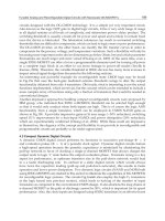
The effect of length-span ratio L/b to the limit load of reticulated vaults supported along the
boundary is very obvious, as shown in Fig.4. The limit load drops rapidly with the increase of L/b at
beginning, but gradually reaches a limit, in most cases as L/b = 2.6, but for high vaults with f/b = 1/2
the curve becomes even more slowly, usually as L/b>~ 3.0.
Figure 4 : Limit load of reticulated vaults supported along boundary with increase of L/b
The reticulated vaults supported along the boundary are not so sensitive to the initial imperfections.
Systematical analysis shows that the reduction in limit load at most consists of 20%, even as the
range of initial imperfections studied approaches a value as big as b/100.
The unsymmetrical distribution of loads nearly does not affect the stability behavior of reticulated
vaults of this type. As revealed by comparative analysis, the limit load defined as the total load p+g
does not decrease under unsymmetrical loading, only with an exception for short vaults of L/b~< 1.2.
For practical application, the effect of unsymmetrical loading to the limit loads of these short vaults
can be considered by a coefficient K2 calculated as:
K2 = 0.6 + 0.4 / ( 1 +2 p/g )
(applicable as p/g = 0-~2)
(3)
It is somewhat difficult to derive the regression formula for the limit loads of reticulated vaults,
because there does not exist any theoretical form that could be referred to like the case with domes.
Anyway, some preliminary forms can be assumed based upon the ideas obtained from the
parametrical analysis. After repeated comparison by trial and error method, the following formula is
finally suggested for predicting the limit loads of reticulated vaults supported along the boundary:
58
S.Z. Shen
911 0-4 B22 029
qcr
= 72.0 R3
L/b) 3 +
1.95 x 1
R(L/b) +
75.0 (R + 3f)b 2 ( 4 )
in which the indexes 11 and 22 indicate the longitudinal and transverse direction, respectively. The
effect of initial imperfections has been considered in the formula. For short vaults with L/b 1.2
coefficient K2 as given by Eqn.3 should be multiplied to consider the effect of possible
unsymmetrical distribution of loads.
Vaults supported on longitudinal edges
To study the vault supported along the boundary, it can be imagined that, with the increase of length
of the vault, the effect of the end diaphragms to the behavior of center part of the vault would
decrease, and the behavior of the vault in general is gradually close to that of a vault supported only
on two longitudinal edges. It's seen now from Eqn.4 that the limit load decreases with L/b increasing,
and only the third term of the formula will be retained as L/b approaches infinitive. It leads to a very
interesting question: if the third term of the formula can be used to evaluate the limit load of the vault
supported on two longitudinal edges. This theoretical deduction was proved by the complete-process
analysis of 54 examples of reticulated vaults of such kind. It's then concluded that the limit load of
reticulated vaults supported on two longitudinal edges can be predicted by the formula as follows:
qcr
=75.0 D22
(R +3f)b2 (5)
The effect of unsymmetrical distribution of loads need not be considered for vaults of this type.
Vaults supported at two ends
The vault supported at two ends has free longitudinal edges, but strengthened by edge beams with
certain rigidity. Such a vault is behaving like a huge beam with curve cross-section supported at two
end diaphragms. With the increase of length of the vault, the member forces in the vault, and hence
the cross-section of the members, increase as well, that is not like the vault supported along the
boundary. So, if keeping the other parameters unchanged, the member sections determined by
calculation as in practical design are different for vaults with different length. Under this condition,
the parametrical analysis shows that the limit loads of the vaults are rather stable for different values
of length-width ratio L/b. That is, the limit load does not depend evidently upon the ratio L/b.
The buckling mode of the vaults has more likely a form of overall deformation of the surface
together with the bending and torsion of edge beams. The raise-width ratio f/b has obvious effect to
the limit load of the vaults: the vault with bigger f/b ratio shows higher stability load-capacity.
The vaults supported at two ends are not so sensitive to initial imperfections. As revealed by
systematical analysis, if taking b/300 as the acceptable maximum value of initial imperfection, the
reduction in limit load does not exceed 18%.
The limit load is evidently affected by unsymmetrical distribution of loads. Such effect becomes
sufficiently developed as early as p/g = 0.5, and the further reduction in limit load is not evident for
Design Formulas for Stability Analysis of Reticulated Shells
59
the bigger values of ratio p/g. For practical application the effect of unsymmetrical loading can be
considered by the coefficient K2 determined as follows:
K2 = 1.0- 0.2 L/b ( L/b = 1.0-2.5 ) ( 6 )
K2 = 0.5 ( L/b = 2.5"`3.0 )
The intermediate diaphragms for relatively long vaults supported at two ends may be arranged at an
interval roughly equal to the width b in order to increase the overall rigidity of the surface and hence
to raise the limit load of the vaults. On the bases of systematical comparison it's suggested for
practical application that the effect of intermediate diaphragms can be considered by a coefficient K3
calculated by Eqn.7. For vaults with intermediate diaphragms unsymmetrical distribution of loads
does not affect the limit load any more.
K3 = 1.52- 0.12 L/b (applicable as L/b = 1.4 3.0)
(7)
After repeated comparative analysis the regression formula for predicting the limit load of reticulated
vaults supported at the ends is proposed as follows:
qcr - 0.063 + 0.138 + 0.083 ~ ( 8 )
in which the factor
CL
0.96 + 0.16(1.8 - L/b
)4 ;
ih and Iv the horizontal and vertical linear rigidity
of the edge beam, respectively, which can be calculated as ( for latticed beams as usually used ): Ih,v =
E(Alr~2+A2rRR)/L, in which A~ and A2 are the cross-section areas of two chords of the latticed beam, r~
and r2 are the corresponding radiuses of inertia.
The effect of initial imperfections has been included in the formula. The effect of unsymmetrical
loading should be considered by the coefficient K2 given by Eqn.6. For vault with intermediate
diaphragms the limit load determined by Eqn.8 should be multiplied by coefficient K 3 given by
Eqn.7, but without consideration of coefficient K2 9
STABILITY OF RETICULATED SHALLOW SHELLS
The stability behaviors of shallow shells with triangular net system and with orthogonal net system
are somewhat different each from other. In the comparative analysis the corresponding shells of these
two kinds were designed to have equal weight. Under this condition, the limit load of the shells with
triangular system is higher than that of the other. The buckling of the shells with orthogonal system
more likely has a form of local concave on the surface, but for shells with triangular system there
appears more evident character of overall deformation, i.e., more obvious deformations arise in a
much wider range of the surface. The shells with triangular system show higher sensitivity to initial
imperfections. According to the comparative analysis, if the maximum value of initial imperfection
is controlled as L/500"`L/300, the reduction in limit load of shells with triangular system and with
orthogonal system can be taken in practical application as 35% and 25%, respectively.
The shallow shells are very sensitive to unsymmetrical distribution of loads. As an example, the limit
loads of a shell with a plan of 30"30m and with orthogonal system varying with the increase of ratio