Network+ 2005 In Depth (P6) pot
Bạn đang xem bản rút gọn của tài liệu. Xem và tải ngay bản đầy đủ của tài liệu tại đây (704.14 KB, 30 trang )
1000BASE-LX—A Physical layer standard for networks that specifies 1-Gbps transmission
over fiber-optic cable using baseband transmission. 1000BASE-LX can run on either single-
mode or multimode fiber. The “LX” represents its reliance on “long wavelengths” of 1300
nanometers. 1000BASE-LX can extend to 5000-meter segment lengths using single-mode,
fiber-optic cable. 1000BASE-LX networks can use one repeater between segments.
1000BASE-SX—A Physical layer standard for networks that specifies 1-Gbps transmission
over fiber-optic cable using baseband transmission. 1000BASE-SX runs on multimode fiber.
Its maximum segment length is 550 meters. The “SX” represents its reliance on “short wave-
lengths” of 850 nanometers. 1000BASE-SX can use one repeater.
1000BASE-T—A Physical layer standard for achieving 1 Gbps over UTP. 1000BASE-T
achieves its higher throughput by using all four pairs of wires in a CAT 5 or higher twisted-
pair cable to both transmit and receive signals. 1000BASE-T also uses a different data encod-
ing scheme than that used by other UTP Physical layer specifications.
2.4-GHz band—The range of radiofrequencies from 2.4- to 2.4835-GHz.The 2.4-GHz band
is often used for wireless network transmissions.
5-4-3 rule—A guideline for 10-Mbps Ethernet networks stating that between two communi-
cating nodes, the network cannot contain more than five network segments connected by four
repeating devices, and no more than three of the segments may be populated.
802.3ab—The IEEE standard that describes 1000BASE-T, a 1-Gigabit Ethernet technology
that runs over four pairs of CAT 5 or better cable.
802.3ae—The IEEE standard that describes 10-Gigabit Ethernet technologies, including
10GBASE-SR, 10GBASE-ER, and 10GBASE-LR.
802.3u—The IEEE standard that describes Fast Ethernet technologies, including 100BASE-
TX, 100BASE-T4, and 100BASE-FX.
802.3z—The IEEE standard that describes 1000Base (or 1-Gigabit) Ethernet technologies,
including 1000BASE-LX, 1000BASE-SX, and 1000BASE-CX.
access point—See AP.
ad hoc—A type of wireless LAN in which stations communicate directly with each other
(rather than using an access point).
AM (amplitude modulation)—A modulation technique in which the amplitude of the carrier
signal is modified by the application of a data signal.
amplifier—A device that boosts, or strengthens, an analog signal.
amplitude—A measure of a signal’s strength.
amplitude modulation—See AM.
analog—A signal that uses variable voltage to create continuous waves, resulting in an inexact
transmission.
122 Chapter 3
TRANSMISSION BASICS AND NETWORKING MEDIA
AP (access point)—A device used on wireless LANs that transmits and receives wireless sig-
nals to and from multiple nodes and retransmits them to the rest of the network segment.
Access points can connect a group of nodes with a network or two networks with each other.
They may use directional or omni-directional antennas.
attenuation—The extent to which a signal has weakened after traveling a given distance.
bandwidth—A measure of the difference between the highest and lowest frequencies that a
medium can transmit.
baseband—A form of transmission in which digital signals are sent through direct current
pulses applied to a wire. This direct current requires exclusive use of the wire’s capacity, so
baseband systems can transmit only one signal, or one channel, at a time. Every device on a
baseband system shares a single channel.
bend radius—The radius of the maximum arc into which you can loop a cable before you will
cause data transmission errors. Generally, a twisted-pair cable’s bend radius is equal to or greater
than four times the diameter of the cable.
binary—A system founded on using 1s and 0s to encode information.
bit (binary digit)—A bit equals a single pulse in the digital encoding system. It may have only
one of two values: 0 or 1.
braiding—A braided metal shielding used to insulate some types of coaxial cable.
broadband—A form of transmission in which signals are modulated as radiofrequency analog
pulses with different frequency ranges. Unlike baseband, broadband technology does not
involve binary encoding. The use of multiple frequencies enables a broadband system to oper-
ate over several channels and therefore carry much more data than a baseband system.
broadcast—A transmission that involves one transmitter and multiple receivers.
byte—Eight bits of information. In a digital signaling system, broadly speaking, one byte car-
ries one piece of information.
cable modem—A device that modulates and demodulates the broadband cable signals.
cable plant—The hardware that constitutes the enterprise-wide cabling system.
capacity—See throughput.
CAT—Abbreviation for the word “category” when describing a type of twisted-pair cable. For
example, Category 3 unshielded twisted-pair cable may also be called CAT 3.
CAT 3 (Category 3)—A form of UTP that contains four wire pairs and can carry up to 10
Mbps, with a possible bandwidth of 16 MHz. CAT 3 has typically been used for 10-Mbps
Ethernet or 4-Mbps Token Ring networks. Network administrators are gradually replacing
CAT 3 cabling with CAT 5 to accommodate higher throughput. CAT 3 is less expensive than
CAT 5.
Chapter 3 123
KEY TERMS
CAT 4 (Category 4)—A form of UTP that contains four wire pairs and can support up to 16-
Mbps throughput. CAT 4 may be used for 16-Mbps Token Ring or 10-Mbps Ethernet net-
works. It is guaranteed for data transmission up to 20 MHz and provides more protection
against crosstalk and attenuation than CAT 1, CAT 2, or CAT 3.
CAT 5 (Category 5)—A form of UTP that contains four wire pairs and supports up to 100-
Mbps throughput and a 100-MHz signal rate.
CAT 5e (Enhanced Category 5)—A higher-grade version of CAT 5 wiring that contains high-
quality copper, offers a high twist ratio, and uses advanced methods for reducing crosstalk.
Enhanced CAT 5 can support a signaling rate of up to 350 MHz, more than triple the capa-
bility of regular CAT 5.
CAT 6 (Category 6)—A twisted-pair cable that contains four wire pairs, each wrapped in foil
insulation. Additional foil insulation covers the bundle of wire pairs, and a fire-resistant plas-
tic sheath covers the second foil layer. The foil insulation provides excellent resistance to
crosstalk and enables CAT 6 to support a signaling rate of 250 MHz and at least six times the
throughput supported by regular CAT 5.
CAT 6e (Enhanced Category 6)—A higher-grade version of CAT 6 wiring that further
reduces attenuation and crosstalk and allows for potentially exceeding traditional network seg-
ment length limits. CAT 6e is capable of a 550-MHz signaling rate and can reliably transmit
data at multi-Gigabit per second rates.
CAT 7 (Category 7)—A twisted-pair cable that contains multiple wire pairs, each separately
shielded then surrounded by another layer of shielding within the jacket. CAT 7 can support
up to a 1-GHz signal rate. But because of its extra layers, it is less flexible than other forms of
twisted-pair wiring.
Category 3—See CAT 3.
Category 4—See CAT 4.
Category 5—See CAT 5.
Category 6—See CAT 6.
Category 7—See CAT 7.
channel—A distinct communication path between two or more nodes, much like a lane is a distinct
transportation path on a freeway. Channels may be separated either logically (as in multiplexing) or
physically (as when they are carried by separate wires).
cladding—The glass or plastic shield around the core of a fiber-optic cable. Cladding reflects
light back to the core in patterns that vary depending on the transmission mode. This reflec-
tion allows fiber to bend around corners without impairing the light-based signal.
coaxial cable—A type of cable that consists of a central copper core surrounded by an insula-
tor, a braided metal shielding, called braiding, and an outer cover, called the sheath or jacket.
Coaxial cable, called “coax” for short, was the foundation for Ethernet networks in the 1980s
and remained a popular transmission medium for many years.
124 Chapter 3
TRANSMISSION BASICS AND NETWORKING MEDIA
conduit—The pipeline used to contain and protect cabling. Conduit is usually made from metal.
connectors—The pieces of hardware that connect the wire to the network device, be it a file
server, workstation, switch, or printer.
core—The central component of a cable designed to carry a signal. The core of a fiber-optic
cable, for example, consists of one or several glass or plastic fibers. The core of a coaxial cop-
per cable consists of one large or several small strands of copper.
crossover cable—A twisted-pair patch cable in which the termination locations of the trans-
mit and receive wires on one end of the cable are reversed.
crosstalk—A type of interference caused by signals traveling on nearby wire pairs infringing
on another pair’s signal.
demarcation point (demarc)—The point of division between a telecommunications service
carrier’s network and a building’s internal network.
demultiplexer (demux)—A device that separates multiplexed signals once they are received and
regenerates them in their original form.
dense wavelength division multiplexing—See DWDM.
diffraction—In the context of wireless signal propagation, the phenomenon that occurs when
an electromagnetic wave encounters an obstruction and splits into secondary waves. The sec-
ondary waves continue to propagate in the direction in which they were split. If you could see
wireless signals being diffracted, they would appear to be bending around the obstacle. Objects
with sharp edges—including the corners of walls and desks—cause diffraction.
digital—As opposed to analog signals, digital signals are composed of pulses that can have a
value of only 1 or 0.
direct sequence spread spectrum—See DSSS.
directional antenna—A type of antenna that issues wireless signals along a single direction,
or path.
DSSS (direct sequence spread spectrum)—A transmission technique in which a signal’s bits
are distributed over an entire frequency band at once. Each bit is coded so that the receiver can
reassemble the original signal upon receiving the bits.
duplex—See full-duplex.
DWDM (dense wavelength division multiplexing)—A multiplexing technique used over sin-
gle-mode or multimode fiber-optic cable in which each signal is assigned a different wavelength
for its carrier wave. In DWDM, little space exists between carrier waves, in order to achieve
extraordinary high capacity.
electromagnetic interference—See EMI.
EMI (electromagnetic interference)—A type of interference that may be caused by motors,
power lines, televisions, copiers, fluorescent lights, or other sources of electrical activity.
Chapter 3 125
KEY TERMS
enhanced Category 5—See CAT 5e.
enhanced Category 6—See CAT 6e.
F-Type connector—A connector used to terminate coaxial cable used for transmitting televi-
sion and broadband cable signals.
fading—A change in a wireless signal’s strength as a result of some of the electromagnetic
energy being scattered, reflected, or diffracted after being issued by the transmitter.
Fast Ethernet—A type of Ethernet network that is capable of 100-Mbps throughput.
100BASE-T and 100BASE-FX are both examples of Fast Ethernet.
fault tolerance—The capability for a component or system to continue functioning despite
damage or malfunction.
ferrule—A short tube within a fiber-optic cable connector that encircles the fiber strand and
keeps it properly aligned.
FHSS (frequency hopping spread spectrum)—A wireless signaling technique in which a sig-
nal jumps between several different frequencies within a band in a synchronization pattern
known to the channel’s receiver and transmitter.
fiber-optic cable—A form of cable that contains one or several glass or plastic fibers in its core.
Data is transmitted via pulsing light sent from a laser or light-emitting diode (LED) through
the central fiber (or fibers). Fiber-optic cables offer significantly higher throughput than cop-
per-based cables. They may be single-mode or multimode and typically use wave-division
multiplexing to carry multiple signals.
fixed—A type of wireless system in which the locations of the transmitter and receiver are sta-
tic. In a fixed connection, the transmitting antenna focuses its energy directly toward the receiv-
ing antenna. This results in a point-to-point link.
FM (frequency modulation)—A method of data modulation in which the frequency of the
carrier signal is modified by the application of the data signal.
frequency—The number of times that a signal’s amplitude changes over a fixed period of
time, expressed in cycles per second, or hertz (Hz).
frequency hopping spread spectrum—See FHSS.
frequency modulation—See FM.
full-duplex—A type of transmission in which signals may travel in both directions over a
medium simultaneously. May also be called, simply, “duplex.”
Gigabit Ethernet—A type of Ethernet network that is capable of 1000 Mbps, or 1 Gbps,
throughput. Examples of Gigabit Ethernet include 1000BASE-T and 1000BASE-CX.
half-duplex—A type of transmission in which signals may travel in both directions over a
medium, but in only one direction at a time.
126 Chapter 3
TRANSMISSION BASICS AND NETWORKING MEDIA
hertz (Hz)—A measure of frequency equivalent to the number of amplitude cycles per second.
impedance—The resistance that contributes to controlling an electrical signal. Impedance is
measured in ohms.
infrared—A type of data transmission in which infrared light signals are used to transmit data
through space, similar to the way a television remote control sends signals across the room. Networks
may use two types of infrared transmission: direct or indirect.
infrastructure WLAN—A type of WLAN in which stations communicate with an access
point and not directly with each other.
latency—The delay between the transmission of a signal and its receipt.
LC (Local Connector)—A connector used with single-mode or multimode fiber-optic cable.
Level 1—A form of UTP that contains two wire pairs. Level 1 is the type of wire used for older
voice networks and is unsuitable for transmitting data.
line-of-sight—See LOS.
link segment—See unpopulated segment.
Local Connector—See LC.
LOS (line-of-sight)—A wireless signal or path that travels directly in a straight line from its
transmitter to its intended receiver. This type of propagation uses the least amount of energy
and results in the reception of the clearest possible signal.
Mechanical Transfer Registered Jack—See MT-RJ.
media converter—A device that enables networks or segments using different media to inter-
connect and exchange signals.
MMF (multimode fiber)—A type of fiber-optic cable that contains a core with a diameter
between 50 and 100 microns, through which many pulses of light generated by a light-
emitting diode (LED) travel at different angles.
mobile—A type of wireless system in which the receiver can be located anywhere within the
transmitter’s range. This allows the receiver to roam from one place to another while continu-
ing to pick up its signal.
modal bandwidth—A measure of the highest frequency of signal a multimode fiber-optic cable can
support over a specific distance. Modal bandwidth is measured in MHz-km.
modem—A device that modulates analog signals into digital signals at the transmitting end
for transmission over telephone lines, and demodulates digital signals into analog signals at the
receiving end.
modulation—A technique for formatting signals in which one property of a simple carrier
wave is modified by the addition of a data signal during transmission.
Chapter 3 127
KEY TERMS
MT-RJ (Mechanical Transfer Registered Jack)—A connector used with single-mode or mul-
timode fiber-optic cable.
multimode fiber—See MMF.—
multipath—The characteristic of wireless signals that follow a number of different paths to their des-
tination (for example, because of reflection, diffraction, and scattering).
multiplexer (mux)—A device that separates a medium into multiple channels and issues sig-
nals to each of those subchannels.
multiplexing—A form of transmission that allows multiple signals to travel simultaneously
over one medium.
narrowband—A type of wireless transmission in which signals travel over a single frequency
or within a specified frequency range.
noise—The unwanted signals, or interference, from sources near network cabling, such as elec-
trical motors, power lines, and radar.
omnidirectional antenna—A type of antenna that issues and receives wireless signals with
equal strength and clarity in all directions. This type of antenna is used when many different
receivers must be able to pick up the signal, or when the receiver’s location is highly mobile.
optical loss—The degradation of a light signal on a fiber-optic network.
overhead—The nondata information that must accompany data in order for a signal to be
properly routed and interpreted by the network.
patch cable—A relatively short section (usually between 3 and 25 feet) of cabling with con-
nectors on both ends.
patch panel—A wall-mounted panel of data receptors into which cross-connect patch cables
from the punch-down block are inserted.
PDA (personal digital assistant)—A handheld computer. PDAs normally use a stylus for
user input and often communicate via infrared or another wireless signaling method.
personal digital assistant—See PDA.
phase—A point or stage in a wave’s progress over time.
plenum—The area above the ceiling tile or below the subfloor in a building.
point-to-point—A data transmission that involves one transmitter and one receiver.
populated segment—A network segment that contains end nodes, such as workstations.
punch-down block—A panel of data receptors into which horizontal cabling from the work-
stations is inserted.
radiation pattern—The relative strength over a three-dimensional area of all the electromag-
netic energy an antenna sends or receives.
128 Chapter 3
TRANSMISSION BASICS AND NETWORKING MEDIA
radiofrequency interference—See RFI.
range—The geographical area in which signals issued from an antenna or wireless system can
be consistently and accurately received.
reflection—In the context of wireless, the phenomenon that occurs when an electromagnetic
wave encounters an obstacle and bounces back toward its source. A wireless signal will bounce
off objects whose dimensions are large compared to the signal’s average wavelength.
regeneration—The process of retransmitting a digital signal. Regeneration, unlike amplifica-
tion, repeats the pure signal, with none of the noise it has accumulated.
repeater—A device used to regenerate a signal.
RFI (radiofrequency interference)—A kind of interference that may be generated by broad-
cast signals from radio or TV towers.
RG-6—A type of coaxial cable used for television, satellite, and broadband cable connections.
risers—The backbone cabling that provides vertical connections between floors of a building.
RJ-11 (Registered Jack 11)—The standard connector used with unshielded twisted-pair
cabling (usually CAT 3 or Level 1) to connect analog telephones.
RJ-45 (Registered Jack 45)—The standard connector used with shielded twisted-pair and
unshielded twisted-pair cabling.
round trip time—See RTT.
RTT (round trip time)—The length of time it takes for a packet to go from sender to receiver, then
back from receiver to sender. RTT is usually measured in milliseconds.
SC (Subscriber Connector or Standard Connector)—A connector used with single-mode or
multimode fiber-optic cable.
scattering—The diffusion of a wireless signal that results from hitting an object that has
smaller dimensions compared to the signal’s wavelength. Scattering is also related to the rough-
ness of the surface a wireless signal encounters. The rougher the surface, the more likely a sig-
nal is to scatter when it hits that surface.
sheath—The outer cover, or jacket, of a cable.
shielded twisted-pair—See STP.
simplex—A type of transmission in which signals may travel in only one direction over a
medium.
single-mode fiber—See SMF.
SMF (single-mode fiber)—A type of fiber-optic cable with a narrow core that carries light
pulses along a single path data from one end of the cable to the other end. Data can be trans-
mitted faster and for longer distances on single-mode fiber than on multimode fiber. However,
single-mode fiber is more expensive.
Chapter 3 129
KEY TERMS
spread spectrum—A type of wireless transmission in which lower-level signals are distributed
over several frequencies simultaneously. Spread spectrum transmission is more secure than
narrowband.
ST (Straight Tip)—A connector used with single-mode or multimode fiber-optic cable.
Standard Connector—See SC.
station—An end node on a network; used most often in the context of wireless networks.
statistical multiplexing—A method of multiplexing in which each node on a network is
assigned a separate time slot for transmission, based on the node’s priority and need.
STP (shielded twisted-pair)—A type of cable containing twisted-wire pairs that are not only
individually insulated, but also surrounded by a shielding made of a metallic substance such as
foil.
straight-through cable—A twisted-pair patch cable in which the wire terminations in both
connectors follow the same scheme.
Straight Tip—See ST.
structured cabling—A method for uniform, enterprise-wide, multivendor cabling systems
specified by the TIA/EIA 568 Commercial Building Wiring Standard. Structured cabling is
based on a hierarchical design using a high-speed backbone.
subchannel—One of many distinct communication paths established when a channel is mul-
tiplexed or modulated.
Subscriber Connector—See SC.
TDM (time division multiplexing)—A method of multiplexing that assigns a time slot in the flow
of communications to every node on the network and, in that time slot, carries data from that node.
Thicknet—An IEEE Physical layer standard for achieving a maximum of 10-Mbps throughput over
coaxial copper cable. Thicknet is also known as 10BASE-5. Its maximum segment length is 500
meters, and it relies on a bus topology.
thickwire Ethernet—See Thicknet.
thin Ethernet—See Thinnet.
Thinnet—An IEEE Physical layer standard for achieving 10-Mbps throughput over coaxial
copper cable. Thinnet is also known as10BASE-2. Its maximum segment length is 185 meters,
and it relies on a bus topology.
throughput—The amount of data that a medium can transmit during a given period of time.
Throughput is usually measured in megabits (1,000,000 bits) per second, or Mbps. The phys-
ical nature of every transmission media determines its potential throughput.
time division multiplexing—See TDM.
transceiver—A device that transmits and receives signals.
130 Chapter 3
TRANSMISSION BASICS AND NETWORKING MEDIA
transmission—In networking, the application of data signals to a medium or the progress of
data signals over a medium from one point to another.
transmit—To issue signals to the network medium.
twinaxial cable—A type of cable that consists of two copper conductors at its center sur-
rounded by an insulator, a braided metal shielding, called braiding, and an outer cover, called
the sheath or jacket.
twist ratio—The number of twists per meter or foot in a twisted-pair cable.
twisted-pair—A type of cable similar to telephone wiring that consists of color-coded pairs of
insulated copper wires, each with a diameter of 0.4 to 0.8 mm, twisted around each other and
encased in plastic coating.
unpopulated segment—A network segment that does not contain end nodes, such as work-
stations. Unpopulated segments are also called link segments.
unshielded twisted-pair—See UTP.
UTP (unshielded twisted-pair)—A type of cabling that consists of one or more insulated
wire pairs encased in a plastic sheath. As its name implies, UTP does not contain additional
shielding for the twisted pairs. As a result, UTP is both less expensive and less resistant to noise
than STP.
volt—The measurement used to describe the degree of pressure an electrical current exerts on
a conductor.
voltage—The pressure (sometimes informally referred to as the strength) of an electrical cur-
rent.
WAP (wireless access point)—See AP.
wavelength—The distance between corresponding points on a wave’s cycle. Wavelength is
inversely proportional to frequency.
wavelength division multiplexing—See WDM.
WDM (wavelength division multiplexing)—A multiplexing technique in which each signal
on a fiber-optic cable is assigned a different wavelength, which equates to its own subchannel.
Each wavelength is modulated with a data signal. In this manner, multiple signals can be simul-
taneously transmitted in the same direction over a length of fiber.
Webcasting—A broadcast transmission from one Internet-attached node to multiple other
Internet-attached nodes.
wire-bound—A type of signal that relies on a physical medium, such as a cable, for its trans-
mission.
wireless—The signals made of electromagnetic energy that travel through the atmosphere.
wireless access point—See WAP.
Chapter 3 131
REVIEW QUESTIONS
wireless LAN—See WLAN.
wireless spectrum—A continuum of electromagnetic waves used for data and voice communica-
tion.The wireless spectrum (as defined by the FCC, which controls its use) spans frequencies between
9 KHz and 300 GHz. Each type of wireless service can be associated with one area of the wireless
spectrum.
WLAN (wireless LAN)—A LAN that uses wireless connections for some or all of its trans-
missions.
Review Questions
1. A wave’s _________________________ is a measure of its strength at any given point
in time.
a. attenuation
b. wavelength
c. latency
d. amplitude
2. A(n) _________________________ is a distinct communication path between nodes.
a. conduit
b. channel
c. plenum
d. amplifier
3. The most common way to measure latency on data networks is by calculating a
packet’s _________________________.
a. round trip time
b. bend radius
c. modulation
d. fault tolerance
4. A(n) _________________________ issues and receives wireless signals with equal
strength and clarity in all directions.
a. single-mode fiber
b. omni-directional antenna
c. subchannel
d. plenum
132 Chapter 3
TRANSMISSION BASICS AND NETWORKING MEDIA
5. A(n) _________________________ is a device that accepts wireless signals from
multiple nodes and retransmits them to the rest of the network.
a. media converter
b. link segment
c. access point
d. diffraction
6. True or false? A noisy circuit spends more time compensating for the noise, and
therefore has fewer resources available for transmitting data.
7. True or false? A populated segment is a part of a network that connects two network
devices, such as hubs.
8. True or false? 100BASE-FX requires multimode fiber containing at least two strands
of fiber.
9. True or false? Backbone wiring provides interconnection between telecommunications
closets, equipment rooms, and entrance facilities.
10. True or false? Multiplexing is the diffusion, or the reflection in multiple directions, of
a signal.
11. The distance between corresponding points on a wave’s cycle is called its
_________________________.
12. _________________________ is a term used by network professionals to describe the
non-data information that must accompany data in order for a signal to be properly
routed and interpreted by the network.
13. _________________________ occurs when a signal traveling on one wire or cable
infringes on the signal traveling over an adjacent wire or cable.
14. _________________________ cable consists of twisted wire pairs that are not only
individually insulated, but also surrounded by a shielding made of a metallic sub-
stance, such as foil.
15. _________________________ is the capacity for a component or system to continue
functioning despite damage or partial malfunction.
Chapter 3 133
REVIEW QUESTIONS
This page intentionally left blank
Network Protocols
Chapter 4
After reading this chapter and completing the exercises, you will be able to:
■ Identify the characteristics of TCP/IP, IPX/SPX, NetBIOS, and
AppleTalk
■ Understand how network protocols correlate to layers of the OSI Model
■ Identify the core protocols of the TCP/IP suite and describe their
functions
■ Identify the well-known ports for key TCP/IP services
■ Understand addressing schemes for TCP/IP, IPX/SPX, NetBEUI, and
AppleTalk
■ Describe the purpose and implementation of DNS (Domain Name
System) and WINS (Windows Internet Naming Service)
■ Install protocols on Windows XP clients
A
protocol is a rule that governs how networks communicate. Protocols define the standards
for communication between network devices. Without protocols, devices could not inter-
pret the signals sent by other devices, and data would go nowhere. In this chapter, you will learn
about the most commonly used networking protocols, their components, and their functions.
This chapter is not an exhaustive study of protocols, but rather a practical guide to applying
them. At the end of the chapter, you will have the opportunity to read about some realistic
networking scenarios pertaining to protocols and devise your own solutions. As protocols form
the foundation of network communications, you must fully understand them to manage a net-
work effectively.
Introduction to Protocols
In Chapter 2, you learned about the tasks associated with each layer of the OSI Model, for
example, formatting, addressing, and error correction. You also learned that these tasks are
performed by protocols, which are sets of instructions designed and coded by programmers. In
the networking industry, the term “protocol” is often used to refer to a group, or suite, of indi-
vidual protocols that work together.
Protocols vary according to their purpose, speed, transmission efficiency, utilization of
resources, ease of setup, compatibility, and ability to travel between different LANs. When
choosing protocols, you will need to consider these characteristics, plus network interconnec-
tion and data security requirements. Also keep in mind the limitations that a network’s exist-
ing—and sometimes outdated—hardware and software impose. On long-established networks
a mix of legacy and new technology might require the use of more than one protocol—for
example, IPX/SPX along with TCP/IP. Networks running more than one protocol are called
multiprotocol networks. To manage a multiprotocol network, it is not only important to
know about each protocol suite, but also to understand how they work together.
In the sections that follow, you will learn about the most popular networking protocol suite—
TCP/IP—plus other protocol suites—IPX/SPX, NetBIOS, and AppleTalk—that, although
once popular, have been replaced by TCP/IP on modern networks. For Network+ certifica-
tion, you should understand TCP/IP in depth and be familiar with the other protocol suites.
Keep in mind that you may occasionally encounter additional protocols (such as SNA or
DLC) that are not discussed in this chapter. But if a network was established within the last
few years, chances are that it will rely on TCP/IP. TCP/IP is discussed next.
TCP/IP (Transmission Control
Protocol/Internet Protocol)
TCP/IP (Transmission Control Protocol/Internet Protocol) is not simply one protocol, but
rather a suite of specialized protocols—including TCP, IP, UDP, ARP, and many others—called
subprotocols. Most network administrators refer to the entire group as “TCP/IP,” or some-
times simply “IP.” For example, a network administrator might say, “Our network only runs
IP” when she means that all of the network’s services rely on TCP/IP subprotocols.
TCP/IP’s roots lie with the U.S. Department of Defense, which developed TCP/IP for its
Advanced Research Projects Agency network (ARPAnet, the precursor to today’s Internet) in
the late 1960s. TCP/IP has grown extremely popular thanks to its low cost, its ability to com-
municate between a multitude of dissimilar platforms, and its open nature. “Open” means that
a software developer, for example, can use and modify TCP/IP’s core protocols freely. TCP/IP
is a de facto standard on the Internet and has become the protocol of choice on LANs and
WANs. UNIX and Linux have always relied on TCP/IP. The most recent versions of Netware
and Windows network operating systems also use TCP/IP as their default protocol.
TCP/IP would not have become so popular if it weren’t routable. Protocols that can span more
than one LAN (or LAN segment) are routable, because they carry Network layer addressing
information that can be interpreted by a router. Not all protocols are routable, however. For
example, NetBEUI is not routable. Protocol suites that are not routable do not enable data to
traverse network segments. They are therefore unsuitable for most large networks.
TCP/IP’s popularity is also due to its flexibility. It can run on virtually any combination of
network operating systems or network media. Because of its flexibility, however, TCP/IP may
require more configuration than other protocol suites.
Chapter 4 137
TCP/IP
TCP/IP is a broad topic with numerous technical, historical, and practical aspects. If
you want to become an expert on TCP/IP, you should invest in a book or study guide
solely devoted to this suite of protocols.
NOTE
The TCP/IP Core Protocols
Certain subprotocols of the TCP/IP suite, called TCP/IP core protocols, operate in the Trans-
port or Network layers of the OSI Model and provide basic services to protocols in other lay-
ers. As you might guess, TCP and IP are the most significant protocols in the TCP/IP suite.
These and other core protocols are introduced in the following sections.
NET+
2.4
NET+
2.4
2.10
TCP (Transmission Control Protocol)
TCP (Transmission Control Protocol) operates in the Transport layer of the OSI Model and
provides reliable data delivery services. TCP is a connection-oriented subprotocol, which means
that a connection must be established between communicating nodes before this protocol will
transmit data. TCP further ensures reliable data delivery through sequencing and checksums.
Without such measures, data would be transmitted indiscriminately, without checking whether
the destination node was offline, for example, or whether the data became corrupt during trans-
mission. Finally, TCP provides flow control to ensure that a node is not flooded with data.
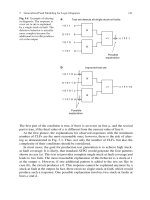
Figure 4-1 depicts the format of a TCP segment, the entity that becomes encapsulated by the
IP datagram in the Network layer (and thus becomes the IP datagram’s “data”). Fields belong-
ing to a TCP segment are described in the following list.
◆ Source port—Indicates the port number at the source node. A port is the address on
a host where an application makes itself available to incoming or outgoing data. One
example of a port is port 80, which is typically used to accept Web page requests
from the HTTP protocol. The Source port field is 16 bits long.
◆ Destination port—Indicates the port number at the destination node. The Destina-
tion port field is 16 bits long.
◆ Sequence number—Identifies the data segment’s position in the stream of data seg-
ments already sent. The Sequence number field is 32 bits long.
◆ Acknowledgment number (ACK)—Confirms receipt of the data via a return message
to the sender. The Acknowledgment number field is 32 bits long.
◆ TCP header length—Indicates the length of the TCP header. This field is 4 bits long.
138 Chapter 4
NETWORK PROTOCOLS
FIGURE 4-1 A TCP Segment
NET+
2.4
2.10
◆ Reserved—A 6-bit field reserved for later use.
◆ Flags—A collection of six 1-bit fields that signal special conditions through flags.
The following flags are available for the sender’s use:
◆ URG—If set to “1,” the Urgent Pointer field contains information for the
receiver.
◆ ACK—If set to “1,” the Acknowledgment field contains information for the
receiver. (If set to “0,” the receiver will ignore the Acknowledgment field.)
◆ PSH—If set to “1,” it indicates that data should be sent to an application with-
out buffering.
◆ RST—If set to “1,” the sender is requesting that the connection be reset.
◆ SYN—If set to “1,” the sender is requesting a synchronization of the sequence
numbers between the two nodes. This code is used when TCP requests a con-
nection to set the initial sequence number.
◆ FIN—If set to “1,” the segment is the last in a sequence and the connection
should be closed.
◆ Sliding-window size (or window)—Indicates how many bytes the sender can issue to
a receiver while acknowledgment for this segment is outstanding. This field per-
forms flow control, preventing the receiver from being deluged with bytes. For
example, suppose a server indicates a sliding window size of 4000 bytes. Also sup-
pose the client has already issued 1000 bytes, 250 of which have been received and
acknowledged by the server. That means that the server is still buffering 750 bytes.
Therefore, the client can only issue 3250 additional bytes before it receives acknowl-
edgment from the server for the 750 bytes. This field is 16 bits long.
◆ Checksum—Allows the receiving node to determine whether the TCP segment
became corrupted during transmission. The Checksum field is 16 bits long.
◆ Urgent pointer—Can indicate a location in the data field where urgent data resides.
This field is 16 bits long.
◆ Options—Used to specify special options, such as the maximum segment size a net-
work can handle. The size of this field can vary between 0 and 32 bits.
◆ Padding—Contains filler information to ensure that the size of the TCP header is a
multiple of 32 bits. The size of this field varies; it is often 0.
◆ Data—Contains data originally sent by the source node. The size of the Data field
depends on how much data needs to be transmitted, the constraints on the TCP
segment size imposed by the network type, and the limitation that the segment must
fit within an IP datagram.
In the Chapter 2 discussion of Transport layer functions you learned how TCP establishes con-
nections for HTTP requests. You also saw an example of TCP segment data from an actual
HTTP request. However, you might not have understood what all of the data meant. Now
that you know the function of each TCP segment field, you can interpret its contents. Figure
4-2 offers another look at the TCP segment.
Chapter 4 139
TCP/IP
NET+
2.4
2.10
Suppose the segment in Figure 4-2 was sent from Computer B to Computer A. Begin inter-
preting the segment at the “Source port” line. Notice the segment was issued from Computer
B’s port 80, the port assigned to HTTP by default. It was addressed to port 1958 on Com-
puter A. The sequence number for this segment is 3043958669. The next segment that Com-
puter B expects to receive from Computer A will have the sequence number of 937013559,
because this is what Computer B has entered in the Acknowledgment field. By simply having
a value, the Acknowledgment field performs its duty of letting a node know that its last com-
munication was received. By indicating a sequence number, the Acknowledgment field does
double-duty. Next, look at the Header length field. It indicates that the TCP header is 24
bytes long—4 bytes larger than its minimum size—which means that some of the available
options were specified or the padding space was used.
In the flags category, notice that there are two unfamiliar flags: Congestion Window Reduced
and ECN-Echo. These are optional flags that can be used to help TCP react to and reduce
traffic congestion. They are only available when TCP is establishing a connection. However in
this segment, they are not set. Of all the possible flags in the Figure 4-2 segment, only the
ACK and SYN flags are set. That means that Computer B is acknowledging the last segment
it received from Computer A and also negotiating a synchronization scheme for sequencing.
The window size is 5840, meaning that Computer B can accept 5840 more bytes of data from
Computer A even while this segment remains unacknowledged. The Checksum field indicates
the valid outcome of the error-checking algorithm used to verify the segment’s header. In this
case, the checksum is 0x206a. When Computer A receives this segment, it will perform the same
algorithm, and if the result is 0x206a, it will know the TCP header arrived without damage.
Finally, this segment uses its option field to specify a maximum TCP segment size of 1460 bytes.
Note that a computer doesn’t “see” the TCP segment as it’s shown in Figure 4-2. This figure
was obtained by using a data analyzer program that translates each packet into a user-friendly
140 Chapter 4
NETWORK PROTOCOLS
FIGURE 4-2 TCP segment data
NET+
2.4
2.10
form. From the computer’s standpoint, the TCP segment is encoded as hexadecimal charac-
ters. (The computer does not need any labels to identify the fields, because as long as TCP/IP
protocol standards are followed, it knows exactly where each byte of data is located.)
The TCP segment pictured in Figure 4-2 is part of the process of establishing a connection
between Computer B and Computer A. In fact, it is the second segment of three used to estab-
lish a TCP connection. In the first step of establishing this connection, Computer A issues a
message to Computer B with its SYN bit set, indicating the desire to communicate and syn-
chronize sequence numbers. In its message it sends a random number that will be used to syn-
chronize the communication. In Figure 4-3, for example, this number is 937013558. (Its ACK
bit is usually set to 0.) After Computer B receives this message it responds with a segment whose
ACK and SYN flags are both set. In Computer B’s transmission, the ACK field contains a num-
ber that equals the sequence number Computer A originally sent plus 1. As Figure 4-3 illus-
trates, Computer B sends the number 937013559. In this manner Computer B signals to
Computer A that it has received the request for communication and further, it expects Com-
puter A to respond with the sequence number 937013559. In its SYN field, Computer B sends
its own random number (in Figure 4-3, this number is 3043958669), which Computer A will
use to acknowledge that it received Computer B’s transmission. Next, Computer A issues a seg-
ment whose sequence number is 937013559 (because this is what Computer B indicated it
expected to receive). In the same segment, Computer A also communicates a sequence number
via its Acknowledgment field. This number equals the sequence number that Computer B sent
plus 1. In the example shown in Figure 4-3, Computer A expects 3043958670 to be the sequence
number of the next segment it receives from Computer B. Thus, in its next communication
Chapter 4 141
TCP/IP
FIGURE 4-3 Establishing a TCP connection
NET+
2.4
2.10
(not shown in Figure 4-3), Computer B will respond with a segment whose sequence number
is 937013560. The two nodes continue communicating this way until Computer A issues a seg-
ment whose FIN flag is set, indicating the end of the transmission.
TCP is not the only core protocol at the Transport layer. A similar but less complex protocol,
UDP, is discussed next.
UDP (User Datagram Protocol)
UDP (User Datagram Protocol), like TCP, belongs to the Transport layer of the OSI Model.
Unlike TCP, however, UDP is a connectionless transport service. In other words, UDP offers
no assurance that packets will be received in the correct sequence. In fact, this protocol does not
guarantee that the packets will be received at all. Furthermore, it provides no error checking or
sequencing. Nevertheless, UDP’s lack of sophistication makes it more efficient than TCP. It can
be useful in situations where a great volume of data must be transferred quickly, such as live audio
or video transmissions over the Internet. In these cases, TCP—with its acknowledgments,
checksums, and flow control mechanisms—would only add more overhead to the transmission.
UDP is also more efficient for carrying messages that fit within one data packet.
In contrast to a TCP header’s 10 fields, the UDP header contains only four fields: Source port,
Destination port, Length, and Checksum. Use of the Checksum field in UDP is optional.
Figure 4-4 depicts a UDP segment. Contrast its header with the much larger TCP segment
header shown in Figure 4-1.
142 Chapter 4
NETWORK PROTOCOLS
FIGURE 4-4 A UDP Segment
Now that you understand the functions of and differences between TCP and UDP, you are
ready to learn more about the Internet Protocol (IP).
IP (Internet Protocol)
IP (Internet Protocol) belongs to the Network layer of the OSI Model. It provides informa-
tion about how and where data should be delivered, including the data’s source and destination
addresses. IP is the subprotocol that enables TCP/IP to internetwork—that is, to traverse more
than one LAN segment and more than one type of network through a router.
NET+
2.4
2.10
NET+
2.4
2.10
NET+
2.10
As you know, at the Network layer of the OSI Model, data is formed into packets. In the con-
text of TCP/IP, a packet is also known as an IP datagram. The IP datagram acts as an enve-
lope for data and contains information necessary for routers to transfer data between different
LAN segments. IP is an unreliable, connectionless protocol, which means that it does not guar-
antee delivery of data. Higher-level protocols of the TCP/IP suite, however, use IP to ensure
that data packets are delivered to the right addresses. Note that the IP datagram does contain
one reliability component, the Header checksum, which verifies only the integrity of the rout-
ing information in the IP header. If the checksum accompanying the message does not have
the proper value when the packet is received, then the packet is presumed to be corrupt and is
discarded; at that point, a new packet is sent.
Figure 4-5 depicts the format of an IP datagram. Its fields are described in the following list.
◆ Version—Identifies the version number of the protocol—for example, IPv4 or IPv6.
The receiving workstation looks at this field first to determine whether it can read
the incoming data. If it cannot, it will reject the packet. Rejection rarely occurs,
however, because most TCP/IP-based networks use IPv4. This field is 4 bits long.
◆ Internet Header Length (IHL)—Identifies the number of 4-byte (or 32-bit) blocks in
the IP header. The most common header length comprises five groupings, as the
Chapter 4 143
TCP/IP
The following sections describe the IP subprotocol as it is used in IPv4 (IP version
4), the original version that has been used for 20 years and is still used by most net-
works today.
NOTE
FIGURE 4-5 An IP Datagram
NET+
2.4
2.10
minimum length of an IP header is 20 4-byte blocks. This field is important because
it indicates to the receiving node where data will begin (immediately after the header
ends). The IHL field is 4 bits long.
◆ Differentiated Services (DiffServ) Field—Informs routers what level of precedence
they should apply when processing the incoming packet. This field is 8 bits long. It
used to be called the Type of Service (ToS) field, and its purpose was the same as
the re-defined Differentiated Services field. However, the ToS specification allowed
only eight different values regarding the precedence of a datagram, and the field was
rarely used. Differentiated Services allows for up to 64 values and a greater range of
priority handling options.
◆ Total length—Identifies the total length of the IP datagram, including the header and
data, in bytes. An IP datagram, including its header and data, cannot exceed 65,535 bytes.
The Total length field is 16 bits long.
◆ Identification—Identifies the message to which a datagram belongs and enables the
receiving node to reassemble fragmented messages. This field and the following two
fields, Flags and Fragment offset, assist in reassembly of fragmented packets. The
Identification field is 16 bits long.
◆ Flags—Indicates whether a message is fragmented and, if it is fragmented, whether
this datagram is the last in the fragment.
◆ Fragment offset—Identifies where the datagram fragment belongs in the incoming set of
fragments. This field is 13 bits long.
◆ Time to live (TTL)—Indicates the maximum time that a datagram can remain on
the network before it is discarded. Although this field was originally meant to repre-
sent units of time, on modern networks it represents the number of times a data-
gram has been forwarded by a router, or the number of router hops it has endured.
The TTL for datagrams is variable and configurable, but is usually set at 32 or 64.
Each time a datagram passes through a router, its TTL is reduced by 1. When a
router receives a datagram with a TTL equal to 1, it discards that datagram (or more
precisely, the frame to which it belongs). The TTL field in an IP datagram is 8 bits
long.
◆ Protocol—Identifies the type of Transport layer protocol that will receive the data-
gram (for example, TCP or UDP). This field is 8 bits long.
◆ Header checksum—Allows the receiving node to calculate whether the IP header has
been corrupted during transmission. This field is 16 bits long.
◆ Source IP address—Identifies the full IP address (or Network layer address) of the
source node. This field is 32 bits long.
◆ Destination IP address—Indicates the full IP address (or Network layer address) of
the destination node. This field is 32 bits long.
◆ Options—May contain optional routing and timing information. The Options field
varies in length.
144 Chapter 4
NETWORK PROTOCOLS
NET+
2.4
2.10
◆ Padding—Contains filler bits to ensure that the header is a multiple of 32 bits. The
length of this field varies.
◆ Data—Includes the data originally sent by the source node, plus information added
by TCP in the Transport layer. The size of the Data field varies.
In the Chapter 2 discussion of the Network layer functions, you were introduced to IP and the
data contained in its packets. You also saw an example of IP packet data from an actual HTTP
request. However, you might not have understood what all of the data meant. Now that you
are familiar with the fields of an IP datagram, you can interpret its contents. Figure 4-6 offers
another look at the IP packet, with an interpretation below.
Chapter 4 145
TCP/IP
FIGURE 4-6 IP Datagram data
Begin interpreting the datagram with the Version field, which indicates that this transmission
relies on version 4 of the Internet Protocol, which is common for modern networks. Next,
notice that the datagram has a header length of 20 bytes. Because this is the minimum size for
an IP header, you can deduce that the datagram contains no options or padding. In the Dif-
ferentiated Services Field no options for priority handling are set, which is not unusual in rou-
tine data exchanges such as retrieving a Web page. The total length of the datagram is given
as 44 bytes. That makes sense when you consider that its header is 20 bytes, and the TCP seg-
ment that it encapsulates (discussed previously) is 24 bytes. Considering that the maximum size
of an IP packet is 65,535 bytes, this is a very small packet.
Next in the IP datagram is the Identification field, which uniquely identifies the packet. This
packet, the first one issued from Computer B to Computer A in the TCP connection exchange,
is identified in hexadecimal notation as 0x0000. In the Flags field, which indicates whether this
packet is fragmented, the Don’t fragment option is set with a value of 1. So you know that this
packet is not fragmented. And because it’s not fragmented, the fragment offset field does not
apply and is set to 0.
NET+
2.4
2.10
This datagram’s TTL (Time to Live) is set to 64. That means that if the packet were to keep
traveling across a network, it would be allowed 64 more hops before it was discarded. The Pro-
tocol field is next. It indicates that encapsulated within the IP datagram is a TCP segment.
TCP is always indicated by the hexadecimal string of “0x06.” The next field provides the cor-
rect header checksum answer, which is used by the recipient of this packet to determine whether
the IP datagram’s header was damaged in transit. Finally, the last two fields in the datagram
show the logical addresses for the packet’s source and destination.
In the next section you learn about another protocol that operates in the Network layer of the
OSI Model, ICMP.
ICMP (Internet Control Message Protocol)
Whereas IP helps direct data to its correct destination, ICMP (Internet Control Message Pro-
tocol) is a Network layer protocol that reports on the success or failure of data delivery. It can
indicate when part of a network is congested, when data fails to reach its destination, and
when data has been discarded because the allotted time for its delivery (its TTL) expired.
ICMP announces these transmission failures to the sender, but ICMP cannot correct any of
the errors it detects; those functions are left to higher-layer protocols, such as TCP. However,
ICMP’s announcements provide critical information for troubleshooting network problems.
IGMP (Internet Group Management Protocol)
Another key subprotocol in the TCP/IP suite is IGMP (Internet Group Management Pro-
tocol or Internet Group Multicast Protocol). IGMP operates at the Network layer and man-
ages multicasting. Multicasting is a transmission method that allows one node to send data to
a defined group of nodes (not necessarily the entire network segment, as is the case of a broad-
cast transmission). Whereas most data transmission occurs on a point-to-point basis, multi-
casting is a point-to-multipoint method. Multicasting can be used for teleconferencing or
videoconferencing over the Internet, for example. Routers use IGMP to determine which nodes
belong to a certain multicast group and to transmit data to all nodes in that group. Network
nodes use IGMP to join or leave multicast groups at any time.
ARP (Address Resolution Protocol)
ARP (Address Resolution Protocol) is a Network layer protocol that obtains the MAC (phys-
ical) address of a host, or node, then creates a database that maps the MAC address to the host’s
IP (logical) address. If one node needs to know the MAC address of another node on the same
network, the first node issues a broadcast message to the network, using ARP, that essentially
says, “Will the computer with the IP address 1.2.3.4 please send me its MAC address?” In the
context of networking, a broadcast is a transmission that is simultaneously sent to all nodes on
a particular network segment. The node that has the IP address 1.2.3.4 then broadcasts a reply
that contains the physical address of the destination host.
146 Chapter 4
NETWORK PROTOCOLS
NET+
2.4
2.10
NET+
2.10