Network+ 2005 In Depth (P10) doc
Bạn đang xem bản rút gọn của tài liệu. Xem và tải ngay bản đầy đủ của tài liệu tại đây (878.82 KB, 30 trang )
routing switch—See Layer 3 switch.
runt—An erroneously shortened packet.
single point of failure—A device or connection on a network that, were it to fail, could cause
the entire network to stop functioning.
SOHO (small office-home office) router—A router designed for use on small office or home
office networks. SOHO routers typically have no more than eight data ports and do not offer
advanced features such as traffic prioritization, network management, or hardware redun-
dancy.
stackable hub—A type of hub designed to be linked with other hubs in a single telecommu-
nications closet. Stackable hubs linked together logically represent one large hub to the net-
work.
standalone hub—A type of hub that serves a workgroup of computers that are separate from
the rest of the network, also known as a workgroup hub.
static routing—A technique in which a network administrator programs a router to use spe-
cific paths between nodes. Because it does not account for occasional network congestion, failed
connections, or device moves, static routing is not optimal.
store and forward mode—A method of switching in which a switch reads the entire data frame
into its memory and checks it for accuracy before transmitting it. Although this method is more
time-consuming than the cut-through method, it allows store and forward switches to trans-
mit data more accurately.
switch—A connectivity device that logically subdivides a network into smaller, individual col-
lision domains. A switch operates at the Data Link layer of the OSI Model and can interpret
MAC address information to determine whether to filter (discard) or forward packets it
receives.
system bus—See bus.
uplink port—A port on a connectivity device, such as a hub or switch, used to connect it to
another connectivity device.
USB (universal serial bus) port—A standard external bus that can be used to connect multi-
ple types of peripherals, including modems, mice, and NICs, to a computer. Two USB stan-
dards exist: USB 1.1 and USB 2.0. Most modern computers support the USB 2.0 standard.
virtual local area network—See VLAN.
VLAN (virtual local area network)—A network within a network that is logically defined by
grouping its devices’ switch ports in the same broadcast domain. A VLAN can consist of any
type of network node in any geographic location and can incorporate nodes connected to dif-
ferent switches.
workgroup hub—See standalone hub.
242 Chapter 5
NETWORKING HARDWARE
Review Questions
1. _________________________ are connectivity devices that enable a workstation,
server, printer, or other node to receive and transmit data over the network media.
a. Network interface cards
b. Adapter cards
c. Routing protocols
d. Ports
2. A computer’s _________________________ is the circuit, or signaling pathway, used
by the motherboard to transmit data to the computer’s components, including its
memory, processor, hard disk, and NIC.
a. port
b. bus
c. switch
d. router
3. _________________________ is a standard interface used to connect multiple types
of peripherals, including modems, mice, audio players, and NICs.
a. OSPF
b. PCI
c. FireWire
d. USB
4. _________________________ are physically designed to be linked with other hubs in
a single telecommunications closet.
a. Firewalls
b. Gateway routers
c. Stackable hubs
d. Jumpers
5. _________________________ are connectivity devices that subdivide a network into
smaller logical pieces.
a. Switches
b. Segments
c. Jumpers
d. Hubs
Chapter 5 243
REVIEW QUESTIONS
6. True or false? All peripheral devices are connected to a computer’s motherboard via an
expansion slot or peripheral bus.
7. True or false? A device’s base I/O port cannot be used by any other device.
8. True or false? A repeater is limited in function but not in scope.
9. True or false? A switch running in cut-through mode will read a frame’s header and
decide where to forward the data before it receives the entire packet.
10. True or false? A router is a multiport connectivity device that directs data between
nodes on a network.
11. A(n) _________________________ is a small, removable piece of plastic that con-
tains a metal receptacle.
12. A(n) _________________________ is a message to the computer that instructs it to
stop what it is doing and pay attention to something else.
13. The _________________________ indicates, in hexadecimal notation, the area of
memory that the NIC and CPU will use for exchanging, or buffering, data.
14. A(n) _________________________ is a connector that plugs into a port, such as a
serial or parallel or an RJ-45 port, and crosses over the transmit line to the receive line
so that outgoing signals can be redirected into the computer for testing.
15. A(n) _________________________ is a logically or physically distinct Ethernet net-
work segment on which all participating devices must detect and accommodate data
collisions.
244 Chapter 5
NETWORKING HARDWARE
Topologies and
Access Methods
Chapter 6
After reading this chapter and completing the exercises, you will be able to:
■ Describe the basic and hybrid LAN physical topologies, and their uses,
advantages, and disadvantages
■ Describe the backbone structures that form the foundation for most
LANs
■ Compare the different types of switching used in data transmission
■ Understand the transmission methods underlying Ethernet,Token Ring,
FDDI, and ATM networks
■ Describe the characteristics of different wireless network technologies,
including Bluetooth and the three IEEE 802.11 standards
J
ust as an architect of a house must decide where to place walls and doors, where to install
electrical and plumbing systems, and how to manage traffic patterns through rooms to
make a house more livable, a network architect must consider many factors, both seen and
unseen, when designing a network. This chapter details some basic elements of network archi-
tecture: physical and logical topologies. These elements are crucial to understanding network-
ing design, troubleshooting, and management, all of which are discussed later in this book.
In this chapter, you will also learn about the most commonly used network access methods:
Ethernet, Token Ring, FDDI, ATM, and popular wireless access methods. Once you master
the physical and logical fundamentals of network architecture, you will have all the tools nec-
essary to design a network as elegant as the Taj Mahal.
Simple Physical Topologies
A physical topology is the physical layout, or pattern, of the nodes on a network. It depicts a
network in broad scope; that is, it does not specify device types, connectivity methods, or
addressing schemes for the network. Physical topologies are divided into three fundamental
geometric shapes: bus, ring, and star. These shapes can be mixed to create hybrid topologies.
Before you design a network, you need to understand physical topologies, because they are inte-
gral to the type of network (for example, Ethernet or Token Ring), cabling infrastructure, and
transmission media you use. You must also understand a network’s physical topology to trou-
bleshoot its problems or change its infrastructure. A thorough knowledge of physical topolo-
gies is necessary to obtain Network+ certification.
Physical topologies and logical topologies (discussed later) are two different network-
ing concepts. You should be aware that when used alone, the word “topology” often
refers to a network’s physical topology.
TIP
Bus
A bus topology consists of a single cable connecting all nodes on a network without inter-
vening connectivity devices. The single cable is called the bus and can support only one chan-
nel for communication; as a result, every node shares the bus’s total capacity. Most bus
networks—for example, Thinnet and Thicknet—use coaxial cable as their physical medium.
NET+
1.1
On a bus topology network, devices share the responsibility for getting data from one point to
another. Each node on a bus network passively listens for data directed to it. When one node
wants to transmit data to another node, it broadcasts an alert to the entire network, informing
all nodes that a transmission is being sent; the destination node then picks up the transmis-
sion. Nodes other than the sending and receiving nodes ignore the message.
For example, suppose that you want to send an instant message to your friend Diane, who works
across the hall, asking whether she wants to have lunch with you. You click the Send button
after typing your message, and the data stream that contains your message is sent to your NIC.
Your NIC then sends a message across the shared wire that essentially says, “I have a message
for Diane’s computer.” The message passes by every NIC between your computer and Diane’s
computer until Diane’s computer recognizes that the message is meant for it and responds by
accepting the data.
At the ends of each bus network are 50-ohm resistors known as terminators. Terminators stop
signals after they have reached the end of the wire. Without these devices, signals on a bus
network would travel endlessly between the two ends of the network—a phenomenon known
as signal bounce—and new signals could not get through. To understand this concept, imag-
ine that you and a partner, standing at opposite sides of a canyon, are yelling to each other.
When you call out, your words echo; when your partner replies, his words also echo. Now imag-
ine that the echoes never fade. After a short while, you could not continue conversing because
all of the previously generated sound waves would still be bouncing around, creating too much
noise for you to hear anything else. On a network, terminators prevent this problem by halt-
ing the transmission of old signals. In some cases, a hub provides termination for one end of a
segment. A bus network must also be grounded at one end to help remove static electricity
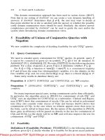
that could adversely affect the signal. Figure 6-1 depicts a terminated bus network.
Chapter 6 247
SIMPLE PHYSICAL TOPOLOGIES
FIGURE 6-1 A terminated bus topology network
NET+
1.1
Although networks based on a bus topology are relatively inexpensive to set up, they do not scale
well. As you add more nodes, the network’s performance degrades. Because of the single-chan-
nel limitation, the more nodes on a bus network, the more slowly the network will transmit and
deliver data. For example, suppose a bus network in your small office supports two workstations
and a server, and saving a file to the server takes two seconds. During that time, your NIC first
checks the communication channel to ensure it is free, then issues data directed to the server.
When the data reaches the server, the server accepts it. Suppose, however, that your business
experiences tremendous growth, and you add five workstations during one weekend. The fol-
lowing Monday, when you attempt to save a file to the server, the save process might take five
seconds, because the new workstations may also be using the communications channel, and your
workstation may have to wait for a chance to transmit. As this example illustrates, a bus topol-
ogy is rarely practical for networks with more than a dozen workstations.
Bus networks are also difficult to troubleshoot, because it is a challenge to identify fault loca-
tions. To understand why, think of the game called “telephone,” in which one person whispers
a phrase into the ear of the next person, who whispers the phrase into the ear of another per-
son, and so on, until the final person in line repeats the phrase aloud. The vast majority of the
time, the phrase recited by the last person bears little resemblance to the original phrase.
When the game ends, it’s hard to determine precisely where in the chain the individual errors
cropped up. Similarly, errors may occur at any intermediate point on a bus network, but at the
receiving end it’s possible to tell only that an error occurred. Finding the source of the error
can prove very difficult.
A final disadvantage to bus networks is that they are not very fault-tolerant, because a break
or a defect in the bus affects the entire network. As a result, and because of the other disad-
vantages associated with this topology, you will rarely see a network run on a pure bus topol-
ogy. You may, however, encounter hybrid topologies that include a bus component.
Ring
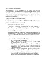
In a ring topology, each node is connected to the two nearest nodes so that the entire network
forms a circle, as shown in Figure 6-2. Data is transmitted clockwise, in one direction (unidi-
rectionally), around the ring. Each workstation accepts and responds to packets addressed to
it, then forwards the other packets to the next workstation in the ring. Each workstation acts
as a repeater for the transmission. The fact that all workstations participate in delivery makes
the ring topology an active topology. This is one way a ring topology differs from a bus topol-
ogy. A ring topology also differs in that it has no “ends” and data stops at its destination. In
most ring networks, twisted-pair or fiber-optic cabling is used as the physical medium.
The drawback of a simple ring topology is that a single malfunctioning workstation can dis-
able the network. For example, suppose that you and five colleagues share a pure ring topology
LAN in your small office. You decide to send an instant message to Thad, who works three
offices away, telling him you found his lost glasses. Between your office and Thad’s office are
two other offices, and two other workstations on the ring. Your instant message must pass
through the two intervening workstations’ NICs before it reaches Thad’s computer. If one of
these workstations has a malfunctioning NIC, your message will never reach Thad.
248 Chapter 6
TOPOLOGIES AND ACCESS METHODS
NET+
1.1
In addition, just as in a bus topology, the more workstations that must participate in data
transmission, the slower the response time. Consequently, pure ring topologies are not very flex-
ible or scalable. Contemporary LANs rarely use pure ring topologies.
Star
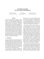
In a star topology, every node on the network is connected through a central device, such as
a hub or switch. Figure 6-3 depicts a typical star topology. Star topologies are usually built
with twisted-pair or fiber-optic cabling. Any single cable on a star network connects only two
devices (for example, a workstation and a hub), so a cabling problem will affect two nodes at
most. Devices such as workstations or printers transmit data to the hub, which then retrans-
mits the signal to the network segment containing the destination node.
Star topologies require more cabling than ring or bus networks. They also require more con-
figuration. However, because each node is separately connected to a central connectivity device,
they are more fault-tolerant. A single malfunctioning workstation cannot disable an entire star
network. A failure in the central connectivity device can take down a LAN segment, though.
Because they include a centralized connection point, star topologies can easily be moved, iso-
lated, or interconnected with other networks; they are therefore scalable. For this reason, and
because of their fault tolerance, the star topology has become the most popular fundamental
layout used in contemporary LANs. Single star networks are commonly interconnected with
other networks through hubs and switches to form more complex topologies. Most Ethernet
networks are based on the star topology.
Chapter 6 249
SIMPLE PHYSICAL TOPOLOGIES
FIGURE 6-2 A typical ring topology network
NET+
1.1
Star networks can support a maximum of only 1024 addressable nodes on a logical network.
For example, if you have a campus with 3000 users, hundreds of networked printers, and scores
of other devices, you must strategically create smaller logical networks. Even if you had 1000
users and could put them on the same logical network, you wouldn’t, because doing so would
result in poor performance and difficult management. Instead, you would use switches to sub-
divide clients and peripherals into many separate broadcast domains.
Hybrid Physical Topologies
Except in very small networks, you will rarely encounter a network that follows a pure bus, ring,
or star topology. Simple topologies are too restrictive, particularly if the LAN must accommo-
date a large number of devices. More likely, you will work with a complex combination of
these topologies, known as a hybrid topology. Several kinds of hybrid topologies are explained
in the following sections.
Star-Wired Ring
The star-wired ring topology uses the physical layout of a star in conjunction with the ring
topology’s data transmission method. In Figure 6-4, which depicts this architecture, the solid
lines represent a physical connection and the dotted lines represent the flow of data. Data is
sent around the star in a circular pattern. This hybrid topology benefits from the fault toler-
ance of the star topology (data transmission does not depend on each workstation to act as a
250 Chapter 6
TOPOLOGIES AND ACCESS METHODS
FIGURE 6-3 A typical star topology network
NET+
1.1
repeater) and the reliability of token passing (discussed later in this chapter). Token Ring net-
works, as specified in IEEE 802.5, use this hybrid topology.
Star-Wired Bus
Another popular hybrid topology combines the star and bus formations. In a star-wired bus
topology, groups of workstations are star-connected to hubs and then networked via a single
bus, as shown in Figure 6-5. With this design, you can cover longer distances and easily inter-
connect or isolate different network segments. One drawback is that this option is more
expensive than using either the star or, especially, the bus topology alone because it requires
more cabling and potentially more connectivity devices. The star-wired bus topology forms
the basis for modern Ethernet and Fast Ethernet networks.
Chapter 6 251
HYBRID PHYSICAL TOPOLOGIES
FIGURE 6-4 A star-wired ring topology network
FIGURE 6-5 A star-wired bus topology network
Backbone Networks
A network backbone is the cabling that connects the hubs, switches, and routers on a network.
Backbones usually are capable of more throughput than the cabling that connects workstations
to hubs. This added capacity is necessary because backbones carry more traffic than any other
cabling in the network. For example, LANs in large organizations commonly rely on a fiber-
optic backbone but continue to use CAT 5 or better UTP to connect hubs or switches with
workstations.
Although even the smallest LAN technically has a backbone, on an enterprise-wide network,
backbones are more complex and more difficult to plan. In networking, the term enterprise
refers to an entire organization, including its local and remote offices, a mixture of computer
systems, and a number of departments. Enterprise-wide computing must therefore take into
account the breadth and diversity of a large organization’s computer needs. The backbone is
the most significant building block of enterprise-wide networks. It may take one of several dif-
ferent shapes, as described in the following sections.
Serial Backbone
A serial backbone is the simplest kind of backbone. It consists of two or more internetwork-
ing devices connected to each other by a single cable in a daisy-chain fashion. In networking,
a daisy chain is simply a linked series of devices. Hubs and switches are often connected in a
daisy chain to extend a network. For example, suppose you manage a small star-wired bus topol-
ogy network in which a single hub serves a workgroup of eight users. When new employees
are added to that department and you need more network connections, you could connect a
second hub to the first hub in a daisy-chain fashion. The new hub would offer open ports for
new users. Because the star-wired hybrids provide for modular additions, daisy chaining is a
logical solution for growth. Also, because hubs can easily be connected through cables attached
to their ports, a LAN’s infrastructure can be expanded with little additional cost.
Hubs are not the only devices that can be connected in a serial backbone. Gateways, routers,
switches, and bridges can also form part of the backbone. Figure 6-6 illustrates a serial back-
bone network, in which the backbone is indicated by a dashed line.
The extent to which you can connect hubs in a serial backbone is limited. For example, in a
10BASE-T network, you may use a maximum of four hubs to connect five network segments
in a serial fashion. Using more hubs than the standard suggests (in other words, exceeding the
maximum network length) will adversely affect the functionality of a LAN. On a 100BASE-
TX network, you may use a maximum of two hubs connecting three network segments. And
on most 1-Gbps networks, you can use only one hub to extend the network. If you extend a
LAN beyond its recommended size, intermittent and unpredictable data transmission errors
will result. Similarly, if you daisy-chain a topology with limited bandwidth, you risk overload-
ing the channel and generating still more data errors.
252 Chapter 6
TOPOLOGIES AND ACCESS METHODS
Distributed Backbone
A distributed backbone consists of a number of connectivity devices connected to a series of
central connectivity devices, such as hubs, switches, or routers, in a hierarchy, as shown in Fig-
ure 6-7. In Figure 6-7, the dashed lines represent the backbone. This kind of topology allows
for simple expansion and limited capital outlay for growth, because more layers of devices can
be added to existing layers. For example, suppose that you are the network administrator for a
small publisher’s office. You might begin your network with a distributed backbone consisting
Chapter 6 253
BACKBONE NETWORKS
FIGURE 6-6 A serial backbone
FIGURE 6-7 A simple distributed backbone
of two switches that supply connectivity to your 20 users, 10 on each switch. When your com-
pany hires more staff, you can connect another switch to one of the existing switches, and use
the new switch to connect the new staff to the network.
A more complicated distributed backbone connects multiple LANs or LAN segments using
routers, as shown in Figure 6-8. In this example, the routers form the highest layer of the
backbone to connect the LANs or LAN segments.
254 Chapter 6
TOPOLOGIES AND ACCESS METHODS
FIGURE 6-8 A distributed backbone connecting multiple LANs
A distributed backbone also provides network administrators with the ability to segregate work-
groups and therefore manage them more easily. It adapts well to an enterprise-wide network
confined to a single building, in which certain hubs or switches can be assigned according to
the floor or department. Note that distributed backbones may include hubs linked in a daisy-
chain fashion. This arrangement requires the same length considerations that serial back-
bones demand. Another possible problem in this design relates to the potential single
points of failure, such as the devices at the uppermost layers. Despite these potential draw-
backs, implementing a distributed backbone network can be relatively simple, quick, and
inexpensive.
Collapsed Backbone
The collapsed backbone topology uses a router or switch as the single central connection point
for multiple subnetworks, as shown in Figure 6-9. Contrast Figure 6-9 with Figure 6-8, in
which multiple LANs are connected via a distributed backbone. In a collapsed backbone, a
single router or switch is the highest layer of the backbone. The router or switch that makes
up the collapsed backbone must contain multiprocessors to handle the heavy traffic going
through it. This is risky because a failure in the central router or switch can bring down the
entire network. In addition, because routers cannot move traffic as quickly as hubs, using a
router may slow data transmission.
Nevertheless, a collapsed backbone topology offers substantial advantages. Most significantly,
this arrangement allows you to interconnect different types of subnetworks. You can also cen-
trally manage maintenance and troubleshooting chores.
Parallel Backbone
A parallel backbone is the most robust type of network backbone. This variation of the col-
lapsed backbone arrangement consists of more than one connection from the central router or
switch to each network segment. In a network with more than one router or switch, the par-
allel backbone calls for duplicate connections between those connectivity devices as well. Fig-
ure 6-10 depicts a simple parallel backbone topology. As you can see, each hub is connected to
the router or switch by two cables, and the two routers are also connected by two cables. The
most significant advantage of using a parallel backbone is that its redundant (duplicate) links
ensure network connectivity to any area of the enterprise. Parallel backbones are more expen-
sive than other enterprise-wide topologies because they require much more cabling than the
others. However, they make up for the additional cost by offering increased performance and
better fault tolerance.
Chapter 6 255
BACKBONE NETWORKS
FIGURE 6-9 A collapsed backbone
As a network administrator, you might choose to implement parallel connections to only some
of the most critical devices on your network. For example, if the first and second hubs in Fig-
ure 6-10 connected your Facilities and Payroll Departments to the rest of the network, and your
organization could never afford to lose connectivity with those departments, you might use a
parallel structure for those links. If the third and fourth hubs in Figure 6-10 connected your
organization’s Recreation and Training Departments to the network, you might decide that par-
allel connections were unnecessary for these departments. By selectively implementing the
parallel structure, you can lower connectivity costs and leave available additional ports on the
connectivity devices.
Bear in mind that an enterprise-wide LAN or WAN may include different combinations of
simple physical topologies and backbone designs. Now that you understand fundamental
physical topologies and backbone networks, you are ready to understand the related concept of
logical topologies.
Logical Topologies
The term logical topology refers to the way in which data is transmitted between nodes, rather
than the physical layout of the paths that data takes. A network’s logical topology will not nec-
essarily match its physical topology.
The most common logical topologies are bus and ring. In a bus logical topology, signals travel
from one network device to all other devices on the network (or network segment). They may
256 Chapter 6
TOPOLOGIES AND ACCESS METHODS
FIGURE 6-10 A parallel backbone
NET+
1.1
or may not travel through an intervening connectivity device (as in a star topology network).
A network that uses a bus physical topology also uses a bus logical topology. In addition, net-
works that use either the star or star-wired bus physical topologies also result in a bus logical
topology.
In contrast, in a ring logical topology, signals follow a circular path between sender and receiver.
Networks that use a pure ring topology use a ring logical topology. The ring logical topology
is also used by the star-wired ring hybrid physical topology because signals follow a circular
path, even as they travel through a connectivity device (as shown by the dashed lines in Figure
6-4). Different types of networks are characterized by one of the two main logical topologies.
For example, Ethernet networks use the bus logical topology, whereas Token Ring networks
use the ring logical topology.
Understanding logical topologies is useful when troubleshooting and designing networks. For
example, on Ethernet networks, it is necessary to understand that all of a segment’s traffic is
transmitted to all nodes in the manner of a bus logical topology. Thus, for example, if one device
has a malfunctioning NIC that is issuing bad or excessive packets, those packets will be detected
by the NICs of all devices on the same segment. The result is a waste of available bandwidth
and potential transmission errors. When network engineers casually refer to topologies, how-
ever, they are most often referring to a network’s physical topology.
Switching
Switching is a component of a network’s logical topology that determines how connections
are created between nodes. There are three methods for switching: circuit switching, message
switching, and packet switching.
Circuit Switching
In circuit switching, a connection is established between two network nodes before they begin
transmitting data. Bandwidth is dedicated to this connection and remains available until the
users terminate communication between the two nodes. While the nodes remain connected,
all data follows the same path initially selected by the switch. When you place a telephone call,
for example, your call typically uses a circuit-switched connection.
Because circuit switching monopolizes its piece of bandwidth while the two stations remain
connected (even when no actual communication is taking place), it can result in a waste of avail-
able resources. However, some network applications benefit from such a “reserved” path. For
example, live audio or videoconferencing might not tolerate the time delay it would take to
reorganize data packets that have taken separate paths through another switching method.
Another example of circuit switching occurs when you connect your home PC via modem to
your Internet service provider’s access server. WAN technologies, such as ISDN and T1 ser-
vice, also use circuit switching, as does ATM, a technology discussed later in this chapter.
Chapter 6 257
SWITCHING
NET+
1.1
NET+
2.14
Message Switching
Message switching establishes a connection between two devices, transfers the information to
the second device, and then breaks the connection. The information is stored and forwarded
from the second device after a connection between that device and a third device on the path
is established. This “store and forward” routine continues until the message reaches its desti-
nation. All information follows the same physical path; unlike with circuit switching, however,
the connection is not continuously maintained. Message switching requires that each device in
the data’s path has sufficient memory and processing power to accept and store the informa-
tion before passing it to the next node. None of the network transmission technologies dis-
cussed in this chapter use message switching.
Packet Switching
A third and by far the most popular method for connecting nodes on a network is packet
switching. Packet switching breaks data into packets before they are transported. Packets can
travel any path on the network to their destination, because each packet contains the destina-
tion address and sequencing information. Consequently, packets can attempt to find the fastest
circuit available at any instant. They need not follow each other along the same path, nor must
they arrive at their destination in the same sequence as when they left their source.
To understand this technology, imagine that you work in Washington, D.C. and you orga-
nized a field trip for 50 colleagues to the National Air and Space Museum. You gave the
museum’s exact address to your colleagues and told them to leave precisely at 7:00 A.M.from
your office building several blocks away. You did not tell your coworkers which route to take.
Some might choose the subway, others might hail a taxicab, and still others might choose to
drive their own cars or even walk. All of them will attempt to find the fastest route to the
museum. But if a group of six decide to take a taxicab and only four people fit in that taxi, the
next two people have to wait for a taxi. Or a taxi might get caught in rush hour traffic and be
forced to find an alternate route. Thus, the fastest route might not be obvious the moment
everyone departs. But no matter which transportation method your colleagues choose, all will
arrive at the museum and reassemble as a group. This analogy illustrates how packets travel in
a packet-switched network.
When packets reach their destination node, the node reassembles them based on their control
information. Because of the time it takes to reassemble the packets into a message, packet
switching is not optimal for live audio or video transmission. Nevertheless, it is a fast and effi-
cient mechanism for transporting typical network data, such as e-mail messages, spreadsheet
files, or even software programs from a server to client. The greatest advantage to packet switch-
ing lies in the fact that it does not waste bandwidth by holding a connection open until a mes-
sage reaches its destination, as circuit switching does. And unlike message switching, it does
not require devices in the data’s path to process any information. Ethernet networks and the
Internet are the most common examples of packet-switched networks.
Now that you are familiar with the various types of switching, you are ready to investigate spe-
cific network technologies that may use switching.
258 Chapter 6
TOPOLOGIES AND ACCESS METHODS
NET+
2.14
Ethernet
As you have learned, Ethernet is a network technology originally developed by Xerox in the
1970s and later improved by Digital Equipment Corporation (DEC), Intel, and Xerox (“DIX”).
This flexible technology can run on a variety of network media and offers excellent through-
put at a reasonable cost. Ethernet is, by far, the most popular network technology used on mod-
ern LANs.
Ethernet has evolved through many variations, and continues to improve. As a result of this
history, it supports many different versions—so many, in fact, that you will probably find the
many variations a little confusing. However, all Ethernet networks have at least one thing in
common—their access method, which is known as CSMA/CD.
CSMA/CD (Carrier Sense Multiple Access with
Collision Detection)
A network’s access method is its method of controlling how network nodes access the com-
munications channel. In comparing a network to a highway, the on-ramps would be one part
of the highway’s access method. A busy highway might use stoplights at each on-ramp to
allow only one person to merge into traffic every five seconds. After merging, cars are restricted
to lanes and each lane is limited as to how many cars it can hold at one time. All of these high-
way controls are designed to avoid collisions and help drivers get to their destinations. On net-
works, similar restrictions apply to the way in which multiple computers share a finite amount
of bandwidth on a network. These controls make up the network’s access method.
The access method used in Ethernet is called CSMA/CD (Carrier Sense Multiple Access
with Collision Detection). All Ethernet networks, independent of their speed or frame type,
rely on CSMA/CD. To understand Ethernet, you must first understand CSMA/CD. Take a
minute to think about the full name “Carrier Sense Multiple Access with Collision Detec-
tion.” The term “Carrier Sense” refers to the fact that Ethernet NICs listen on the network
and wait until they detect (or sense) that no other nodes are transmitting data over the signal
(or carrier) on the communications channel before they begin to transmit. The term “Multiple
Access” refers to the fact that several Ethernet nodes can be connected to a network and can
monitor traffic, or access the media, simultaneously.
In CSMA/CD, when a node wants to transmit data it must first access the transmission media
and determine whether the channel is free. If the channel is not free, it waits and checks again
after a very brief amount of time. If the channel is free, the node transmits its data. Any node
can transmit data after it determines that the channel is free. But what if two nodes simulta-
neously check the channel, determine that it’s free, and begin to transmit? When this happens,
their two transmissions interfere with each other; this is known as a collision.
The last part of the term CSMA/CD, “collision detection,” refers to the way nodes respond to
a collision. In the event of a collision, the network performs a series of steps known as the col-
lision detection routine. If a node’s NIC determines that its data has been involved in a colli-
sion, it immediately stops transmitting. Next, in a process called jamming, the NIC issues a
Chapter 6 259
ETHERNET
NET+
1.2
special 32-bit sequence that indicates to the rest of the network nodes that its previous trans-
mission was faulty and that those data frames are invalid. After waiting, the NIC determines
if the line is again available; if it is available, the NIC retransmits its data.
On heavily trafficked networks, collisions are fairly common. It is not surprising that the more
nodes there are transmitting data on a network, the more collisions that will take place.
(Although a collision rate greater than 5% of all traffic is unusual and may point to a prob-
lematic NIC or poor cabling on the network.) When an Ethernet network grows to include a
particularly large number of nodes, you may see performance suffer as a result of collisions. This
“critical mass” number depends on the type and volume of data that the network regularly trans-
mits. Collisions can corrupt data or truncate data frames, so it is important that the network
detect and compensate for them. Figure 6-11 depicts the way CSMA/CD regulates data flow
to avoid and, if necessary, detect collisions.
260 Chapter 6
TOPOLOGIES AND ACCESS METHODS
FIGURE 6-11 CSMA/CD process
On an Ethernet network, a collision domain is the portion of a network in which collisions
occur if two nodes transmit data at the same time. When designing an Ethernet network, it’s
important to note that because repeaters simply regenerate any signal they receive, they repeat
collisions just as they repeat data. Thus, connecting multiple parts of a network with repeaters
results in a larger collision domain. Higher-layer connectivity devices, such as switches and
routers, however, can separate collision domains.
Collision domains play a role in the Ethernet cabling distance limitations. For example, if
there is more than 100 meters distance between two nodes on a segment connected to the
same 100BASE-TX network bus, data propagation delays will be too long for CSMA/CD to
be effective. A data propagation delay is the length of time data takes to travel from one point
on the segment to another point. When data takes a long time, CSMA/CD’s collision detec-
tion routine cannot identify collisions accurately. In other words, one node on the segment
might begin its CSMA/CD routine and determine that the channel is free even though a sec-
ond node has begun transmitting, because the second node’s data is taking so long to reach the
first node.
NET+
1.2
At rates of 100 or 1000 Mbps, data travels so quickly that NICs can’t always keep up with the
collision detection and retransmission routines. For example, because of the speed employed
on a 100BASE-TX network, the window of time for the NIC to both detect and compensate
for the error is much less than that of a 10BASE-T network. To minimize undetected colli-
sions, 100BASE-TX networks can support only a maximum of three network segments con-
nected with two hubs, whereas 10BaseT buses can support a maximum of five network
segments connected with four hubs. This shorter path reduces the highest potential propaga-
tion delay between nodes.
Switched Ethernet
Traditional Ethernet LANs, called shared Ethernet, supply a fixed amount of bandwidth that
must be shared by all devices on a segment, and all nodes on that segment belong to the same
collision domain. Stations cannot send and receive data simultaneously, nor can they transmit
a signal when another station on the same segment is sending or receiving data. This is because
they share a segment and a hub or repeater, which merely amplifies and retransmits a signal
over the segment. In contrast, a switch can separate a network segment into smaller segments,
with each segment being independent of the others and supporting its own traffic. Switched
Ethernet enables multiple nodes to simultaneously transmit and receive data over different log-
ical network segments. By doing so, each node can individually take advantage of more band-
width. Figure 6-12 shows how switches can isolate network segments.
Using switched Ethernet increases the effective bandwidth of a network segment because fewer
workstations must vie for the same time on the wire. For organizations with existing 10BASE-
T infrastructure, switches offer a relatively simple and inexpensive way to augment each node’s
available bandwidth. Switches can be placed strategically on an organization’s network to balance
Chapter 6 261
ETHERNET
FIGURE 6-12 A switched Ethernet network
NET+
1.2
NET+
1.2
2.14
traffic loads and reduce congestion. Note, however, that switches are not always the best answer
to heavy traffic and a need for greater speeds. In a case in which an enterprise-wise Ethernet LAN
is generally overtaxed, you should consider upgrading the network’s design or infrastructure.
Ethernet Frames
You have already been introduced to data frames, the packages that carry higher-layer data and
control information that enable data to reach their destinations without errors and in the cor-
rect sequence. Ethernet networks may use one (or a combination) of four kinds of data frames:
Ethernet_802.2 (“Raw”), Ethernet_802.3 (“Novell proprietary”), Ethernet_II (“DIX”), and
Ethernet_SNAP. This variety of Ethernet frame types came about as different organizations
released and revised Ethernet standards during the 1980s, changing as LAN technology
evolved. Each frame type differs slightly in the way it codes and decodes packets of data trav-
eling from one device to another.
Physical layer standards, such as 10BASE-T or 100BASE-TX, have no effect on the type of
framing that occurs in the Data Link layer. Thus, Ethernet frame types have no relation to the
topology or cabling characteristics of the network. Framing also takes place independently of
the higher-level layers. Theoretically, all frame types could carry any one of many higher-layer
protocols. For example, a single Ethernet_II data frame may carry either TCP/IP or AppleTalk
data (but not both simultaneously). But as you’ll learn in the following discussion, not all
frame types are well suited to carrying all kinds of traffic.
Using and Configuring Frames
You can use multiple frame types on a network, but you cannot expect interoperability between
the frame types. For example, in a mixed environment of NetWare 4.11 and UNIX servers,
your network might support both Ethernet_802.2 and Ethernet_II frames. A workstation con-
necting to the NetWare 4.11 server might be configured to use the Ethernet_802.2 frame,
whereas a workstation connecting to the UNIX server would likely use the Ethernet_II frame.
A node’s Data Link layer services must be properly configured to expect the types of frames it
might receive. If a node receives an unfamiliar frame type, it will not be able to decode the data
contained in the frame, nor will it be able to communicate with nodes configured to use that
frame type. For this reason, it is important for LAN administrators to ensure that all devices
use the same, correct frame type. These days almost all networks use the Ethernet_II frame
type. But in the 1990s, before this uniformity evolved, the use of different NOSs or legacy hard-
ware often required managing devices to interpret multiple frame types.
Frame types are typically specified through a device’s NIC configuration software. To make
matters easier, most NICs can automatically sense what types of frames are running on a net-
work and adjust themselves to that specification. This feature is called auto-detect, or autosense.
Workstations, networked printers, and servers added to an existing network can all take advan-
tage of auto-detection. Even if your devices use the auto-detect feature, you should neverthe-
less know what frame types are running on your network so that you can troubleshoot
connectivity problems. As easy as it is to configure, the auto-detect feature is not infallible.
262 Chapter 6
TOPOLOGIES AND ACCESS METHODS
NET+
1.2
2.14
NET+
1.2
Frame Fields
All Ethernet frame types share many fields in common. For example, every Ethernet frame
contains a 7-byte preamble and a 1-byte start-of-frame delimiter. The preamble signals to the
receiving node that data is incoming and indicates when the data flow is about to begin. The
SFD (start-of-frame delimiter) identifies where the data field begins. Preambles and SFDs
are not included, however, when calculating a frame’s total size.
Each Ethernet frame also contains a 14-byte header, which includes a destination address, a
source address, and an additional field that varies in function and size, depending on the frame
type. The destination address and source address fields are each 6 bytes long. The destination
address identifies the recipient of the data frame, and the source address identifies the network
node that originally sent the data. Recall that any network device can be identified by its phys-
ical address, also known as a hardware address or Media Access Control (MAC) address. The
source address and destination address fields of an Ethernet frame use the MAC address to
identify where data originated and where it should be delivered.
Also, all Ethernet frames contain a 4-byte FCS (Frame Check Sequence) field. Recall that the
function of the FCS field is to ensure that the data at the destination exactly matches the data
issued from the source using the CRC (Cyclic Redundancy Check) algorithm. Together, the
FCS and the header make up the 18-byte “frame” for the data. The data portion of an Ether-
net frame may contain from 46 to 1500 bytes of information (and recall that this includes the
Network layer datagram). If fewer than 46 bytes of data are supplied by the higher layers, the
source node fills out the data portion with extra bytes until it totals 46 bytes. The extra bytes
are known as padding and have no significance other than to fill out the frame. They do not
affect the data being transmitted.
Adding the 18-byte framing portion plus the smallest possible data field of 46 bytes equals the
minimum Ethernet frame size of 64 bytes. Adding the framing portion plus the largest possi-
ble data field of 1500 bytes equals the maximum Ethernet frame size of 1518 bytes. No mat-
ter what frame type is used, the size range of 64 to 1518 total bytes applies to all Ethernet
frames.
Because of the overhead present in each frame and the time required to enact CSMA/CD, the
use of larger frame sizes on a network generally results in faster throughput. To some extent,
you cannot control your network’s frame sizes. You can, however, help improve network per-
formance by properly managing frames. For example, network administrators should strive to
minimize the number of broadcast frames on their networks, because broadcast frames tend to
be very small and, therefore, inefficient. Also, running more than one frame type on the same
network can result in inefficiencies, because it requires devices to examine each incoming frame
to determine its type. Given a choice, it’s most efficient to support only one frame type on a
network.
Ethernet_II (“DIX”)
Ethernet_II is an Ethernet frame type developed by DEC, Intel, and Xerox (abbreviated as
DIX) before the IEEE began to standardize Ethernet. The Ethernet_II frame type is similar
Chapter 6 263
ETHERNET
NET+
1.2
to the older Ethernet_802.3 and Ethernet_802.2 frame types, but differs in one field. Where
the other types contain a 2-byte length field, the Ethernet_II frame type contains a 2-byte
type field. This type field identifies the Network layer protocol (such as IP, ARP, RARP, or
IPX) contained in the frame. For example, if a frame were carrying an IP datagram, its type
field would contain “0x0800,” the type code for IP. Because Ethernet_802.2 and Ether-
net_802.3 frames do not contain a type field, they are only capable of transmitting data over a
single Network layer protocol (for example, only IP and not both IP and ARP) across the net-
work. For TCP/IP networks, which commonly use multiple Network layer protocols, these
frame types are unsuitable.
Like Ethernet_II, the Ethernet_SNAP frame type also provides a type field. However, the Eth-
ernet_SNAP standard calls for additional control fields, so that compared to Ethernet_II
frames, the Ethernet_SNAP frames allow less room for data. Therefore, because of its support
for multiple Network layer protocols and because it uses fewer bytes as overhead, Ethernet_II
is the frame type most commonly used on contemporary Ethernet networks. Figure 6-13
depicts an Ethernet_II frame.
264 Chapter 6
TOPOLOGIES AND ACCESS METHODS
FIGURE 6-13 Ethernet_II (“DIX”) frame
PoE (Power over Ethernet)
Recently, IEEE has finalized the 802.3af standard, which specifies a method for supplying elec-
trical power over Ethernet connections, also known as PoE (Power over Ethernet). Although
the standard is new, the concept is not. In fact, your home telephone receives power from the
telephone company over the lines that come into your home. This power is necessary for dial
tone and ringing. On an Ethernet network, carrying power over signaling connections can be
useful for nodes that are far from traditional power receptacles or need a constant, reliable power
source. For example, a wireless access point at an outdoor theater, a telephone used to receive
digitized voice signals, an Internet gaming station in the center of a mall, or a critical router at
the core of a network’s backbone can all benefit from PoE.
The PoE standard specifies two types of devices: power sourcing equipment (PSE) and PDs
(powered devices). Power sourcing equipment (PSE) refers to the device that supplies the
power; usually this device depends on backup power sources (in other words, not the electrical
grid maintained by utilities). Powered devices (PDs) are those that receive the power from the
PSE. PoE requires CAT 5 or better copper cable. In the cable, electric current may run over
an unused pair of wires or over the pair of wires used for data transmission in a 10BASE-T,
NET+
1.2
100BASE-TX, or 1000BASE-T network. The standard allows for both approaches; however,
on a single network, the choice of current-carrying pairs should be consistent between all PSE
and PDs. Not all end nodes are capable of receiving PoE. The IEEE standard has accounted
for that possibility by requiring all PSE to first determine whether a node is PoE capable before
attempting to supply it with power. That means that PoE is compatible with current 802.3
installations. No special modifications need to be made to existing networks before adding this
new feature.
Token Ring
Now that you have learned about the many forms of Ethernet, you are ready to learn about
Token Ring, a less common, but still important network access method. Token Ring is a net-
work technology first developed by IBM in the 1980s. In the early 1990s, the Token Ring
architecture competed strongly with Ethernet to be the most popular access method. Since
that time, the economics, speed, and reliability of Ethernet have improved, leaving Token Ring
behind. Because IBM developed Token Ring, a few IBM-centric IT Departments continue
to use it. Other network managers have changed their former Token Ring networks into Eth-
ernet networks.
Token Ring networks have traditionally been more expensive to implement than Ethernet
networks. Proponents of the Token Ring technology argue that, although some of its connec-
tivity hardware is more expensive, its reliability results in less downtime and lower network
management costs than Ethernet. On a practical level, Token Ring has probably lost the bat-
tle for superiority because its developers were slower to develop high-speed standards. Token
Ring networks can run at either 4, 16, or 100 Mbps. The 100-Mbps Token Ring standard,
finalized in 1999, is known as HSTR (High-Speed Token Ring). HSTR can use either
twisted-pair or fiber-optic cable as its transmission medium. Although it is as reliable and effi-
cient, it is still less common than Ethernet because of its higher cost and lagging speed.
Token Ring networks use the token-passing routine and a star-ring hybrid physical topology.
In token passing, a 3-byte packet, called a token, is transmitted from one node to another in
a circular fashion around the ring. When a station has something to send, it picks up the
token, changes it to a frame, and then adds the header, information, and trailer fields. The
header includes the address of the destination node. All nodes read the frame as it traverses the
ring to determine whether they are the intended recipient of the message. If they are, they pick
up the data, then retransmit the frame to the next station on the ring. When the frame finally
reaches the originating station, the originating workstation reissues a free token that can then
be used by another station. The token-passing control scheme avoids the possibility for colli-
sions. This fact makes Token Ring more reliable and efficient than Ethernet. It also does not
impose distance limitations on the length of a LAN segment, unlike CSMA/CD.
On a Token Ring network, one workstation, called the active monitor, acts as the controller for
token passing. Specifically, the active monitor maintains the timing for ring passing, monitors
Chapter 6 265
TOKEN RING
NET+
1.2
token and frame transmission, detects lost tokens, and corrects errors when a timing error or
other disruption occurs. Only one workstation on the ring can act as the active monitor at any
given time.
266 Chapter 6
TOPOLOGIES AND ACCESS METHODS
The Token Ring architecture is often mistakenly described as a pure ring topology. In
fact, its logical topology is a ring. However, its physical topology is a star-ring hybrid
in which data circulate in a ring fashion, but the layout of the network is a star.
NOTE
FIGURE 6-14 Interconnected Token Ring MAUs
NET+
1.2
IEEE standard 802.5 describes the specifications for Token Ring technology. Token Ring net-
works transmit data at either 4, 16, or 100 Mbps over shielded or unshielded twisted-pair
wiring. You may have as many as 255 addressable stations on a Token Ring network that uses
shielded twisted-pair or as many as 72 addressable stations on one that uses unshielded twisted-
pair. All Token Ring connections rely on a NIC that taps into the network through a MAU
(Multistation Access Unit), Token Ring’s equivalent of a hub. NICs can be designed and con-
figured to run specifically on 4-, 16-, or 100-Mbps networks, or they can be designed to accom-
modate all three data transmission rates. In the star-ring hybrid topology, the MAU completes
the ring internally with Ring In and Ring Out ports at either end of the unit. In addition,
MAUs typically provide eight ports for workstation connections. You can easily expand a Token
Ring network by connecting multiple MAUs through their Ring In and Ring Out ports, as
shown in Figure 6-14. Unused ports on a MAU, including Ring In and Ring Out ports, have
self-shorting data connectors that internally close the loop.