Abutments and Retaining Structures pps
Bạn đang xem bản rút gọn của tài liệu. Xem và tải ngay bản đầy đủ của tài liệu tại đây (1.88 MB, 38 trang )
Wang, L., Gong, C. "Abutments and Retaining Structures."
Bridge Engineering Handbook.
Ed. Wai-Fah Chen and Lian Duan
Boca Raton: CRC Press, 2000
© 2000 by CRC Press LLC
29
Abutments and
Retaining Structures
29.1 Introduction
29.2 Abutments
Abutment Types • General Design Considerations •
Seismic Design Considerations • Miscellaneous
Design Considerations • Design Example
29.3 Retaining Structures
Retaining Structure Types • Design Criteria •
Cantilever Retaining Wall Design Example • Tieback
Wall • Reinforced Earth-Retaining Structure •
Seismic Consideration for Retaining Structures
29.1 Introduction
As a component of a bridge, the abutment provides the vertical support to the bridge superstructure
at the bridge ends, connects the bridge with the approach roadway, and retains the roadway base
materials from the bridge spans. Although there are numerous types of abutments and the abut-
ments for the important bridges may be extremely complicated, the analysis principles and design
methods are very similar. In this chapter the topics related to the design of conventional highway
bridge abutments are discussed and a design example is illustrated.
Unlike the bridge abutment, the earth-retaining structures are mainly designed for sustaining
lateral earth pressures. Those structures have been widely used in highway construction. In this
chapter several types of retaining structures are presented and a design example is also given.
29.2 Abutments
29.2.1 Abutment Types
Open-End and Closed-End Abutments
From the view of the relation between the bridge abutment and roadway or water flow that the
bridge overcrosses, bridge abutments can be divided into two categories: open-end abutment, and
closed-end abutment, as shown in Figure 29.1.
For the open-end abutment, there are slopes between the bridge abutment face and the edge of
the roadway or river canal that the bridge overcrosses. Those slopes provide a wide open area for
the traffic flows or water flows under the bridge. It imposes much less impact on the environment
Linan Wang
California Transportation
Department
Chao Gong
ICF Kaiser Engineers, Inc.
© 2000 by CRC Press LLC
and the traffic flows under the bridge than a closed-end abutment. Also, future widening of the
roadway or water flow canal under the bridge by adjusting the slope ratios is easier. However, the
existence of slopes usually requires longer bridge spans and some extra earthwork. This may result
in an increase in the bridge construction cost.
The closed-end abutment is usually constructed close to the edge of the roadways or water canals.
Because of the vertical clearance requirements and the restrictions of construction right of way,
there are no slopes allowed to be constructed between the bridge abutment face and the edge of
roadways or water canals, and high abutment walls must be constructed. Since there is no room or
only a little room between the abutment and the edge of traffic or water flow, it is very difficult to
do the future widening to the roadways and water flow under the bridge. Also, the high abutment
walls and larger backfill volume often result in higher abutment construction costs and more
settlement of road approaches than for the open-end abutment.
Generally, the open-end abutments are more economical, adaptable, and attractive than the
closed-end abutments. However, bridges with closed-end abutments have been widely constructed
in urban areas and for rail transportation systems because of the right-of-way restriction and the
large scale of the live load for trains, which usually results in shorter bridge spans.
FIGURE 29.1
Typical abutment types.
© 2000 by CRC Press LLC
Monolithic and Seat-Type Abutments
Based on the connections between the abutment stem and the bridge superstructure, the abutments
also can be grouped in two categories: the monolithic or end diaphragm abutment and the seat-
type abutment, as shown in Figure 29.1.
The monolithic abutment is monolithically constructed with the bridge superstructure. There is
no relative displacement allowed between the bridge superstructure and abutment. All the super-
structure forces at the bridge ends are transferred to the abutment stem and then to the abutment
backfill soil and footings. The advantages of this type of abutment are its initial lower construction
cost and its immediate engagement of backfill soil that absorbs the energy when the bridge is
subjected to transitional movement. However, the passive soil pressure induced by the backfill soil
could result in a difficult-to-design abutment stem, and higher maintenance cost might be expected.
In the practice this type of abutment is mainly constructed for short bridges.
The seat-type abutment is constructed separately from the bridge superstructure. The bridge
superstructure seats on the abutment stem through bearing pads, rock bearings, or other devices.
This type of abutment allows the bridge designer to control the superstructure forces that are to be
transferred to the abutment stem and backfill soil. By adjusting the devices between the bridge
superstructure and abutment the bridge displacement can be controlled. This type of abutment
may have a short stem or high stem, as shown in Figure 29.1. For a short-stem abutment, the
abutment stiffness usually is much larger than the connection devices between the superstructure
and the abutment. Therefore, those devices can be treated as boundary conditions in the bridge
analysis. Comparatively, the high stem abutment may be subject to significant displacement under
relatively less force. The stiffness of the high stem abutment and the response of the surrounding
soil may have to be considered in the bridge analysis. The availability of the displacement of
connection devices, the allowance of the superstructure shrinkage, and concrete shortening make
this type of abutment widely selected for the long bridge constructions, especially for prestressed
concrete bridges and steel bridges. However, bridge design practice shows that the relative weak
connection devices between the superstructure and the abutment usually require the adjacent
columns to be specially designed. Although the seat-type abutment has relatively higher initial
construction cost than the monolithic abutment, its maintenance cost is relatively lower.
Abutment Type Selection
The selection of an abutment type needs to consider all available information and bridge design
requirements. Those may include bridge geometry, roadway and riverbank requirements, geotech-
nical and right-of-way restrictions, aesthetic requirements, economic considerations, etc. Knowledge
of the advantages and disadvantages for the different types of abutments will greatly benefit the
bridge designer in choosing the right type of abutment for the bridge structure from the beginning
stage of the bridge design.
29.2.2 General Design Considerations
Abutment design loads usually include vertical and horizontal loads from the bridge superstructure,
vertical and lateral soil pressures, abutment gravity load, and the live-load surcharge on the abutment
backfill materials. An abutment should be designed so as to withstand damage from the Earth
pressure, the gravity loads of the bridge superstructure and abutment, live load on the superstructure
or the approach fill, wind loads, and the transitional loads transferred through the connections
between the superstructure and the abutment. Any possible combinations of those forces, which
produce the most severe condition of loading, should be investigated in abutment design. Mean-
while, for the integral abutment or monolithic type of abutment the effects of bridge superstructure
deformations, including bridge thermal movements, to the bridge approach structures must be
© 2000 by CRC Press LLC
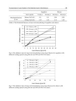
considered in abutment design. Nonseismic design loads at service level and their combinations are
shown in Table 29.1 and Figure 29.2. It is easy to obtain the factored abutment design loads and
load combinations by multiplying the load factors to the loads at service levels. Under seismic
loading, the abutment may be designed at no support loss to the bridge superstructure while the
abutment may suffer some damages during a major earthquake.
The current AASHTO Bridge Design Specifications recommend that either the service load design
or the load factor design method be used to perform an abutment design. However, due to the
uncertainties in evaluating the soil response to static, cycling, dynamic, and seismic loading, the
service load design method is usually used for abutment stability checks and the load factor method
is used for the design of abutment components.
The load and load combinations listed in Table 29.1 may cause abutment sliding, overturning,
and bearing failures. Those stability characteristics of abutment must be checked to satisfy certain
TABLE 29.1
Abutment Design Loads (Service Load Design)
Case
Abutment Design Loads I II III IV V
Dead load of superstructure X X — X X
Dead load of wall and footing XXXXX
Dead load of earth on heel of wall including surcharge XXXX—
Dead load of earth on toe of wall XXXX—
Earth pressure on rear of wall including surcharge XXXX—
Live load on superstructure X — — X —
Temperature and shrinkage — — — X —
Allowable pile capacity of allowable soil pressure in % or basic 100 100 150 125 150
FIGURE 29.2
Configuration of abutment design load and load combinations.
© 2000 by CRC Press LLC
restrictions. For the abutment with spread footings under service load, the factor of safety to resist
sliding should be greater than 1.5; the factor of safety to resist overturning should be greater than
2.0; the factor of safety against soil bearing failure should be greater than 3.0. For the abutment
with pile support, the piles have to be designed to resist the forces that cause abutment sliding,
overturning, and bearing failure. The pile design may utilize either the service load design method
or the load factor design method.
The abutment deep shear failure also needs to be studied in abutment design. Usually, the
potential of this kind of failure is pointed out in the geotechnical report to the bridge designers.
Deep pilings or relocating the abutment may be used to avoid this kind of failure.
29.2.3 Seismic Design Considerations
Investigations of past earthquake damage to the bridges reveal that there are commonly two types
of abutment earthquake damage — stability damage and component damage.
Abutment stability damage during an earthquake is mainly caused by foundation failure due to
excessive ground deformation or the loss of bearing capacities of the foundation soil. Those foun-
dation failures result in the abutment suffering tilting, sliding, settling, and overturning. The
foundation soil failure usually occurs because of poor soil conditions, such as soft soil, and the
existence of a high water table. In order to avoid these kinds of soil failures during an earthquake,
borrowing backfill soil, pile foundations, a high degree of soil compaction, pervious materials, and
drainage systems may be considered in the design.
Abutment component damage is generally caused by excessive soil pressure, which is mobilized
by the large relative displacement between the abutment and its backfilled soil. Those excessive
pressures may cause severe damage to abutment components such as abutment back walls and
abutment wingwalls. However, the abutment component damages do not usually cause the bridge
superstructure to lose support at the abutment and they are repairable. This may allow the bridge
designer to utilize the deformation of abutment backfill soil under seismic forces to dissipate the
seismic energy to avoid the bridge losing support at columns under a major earthquake strike.
The behavior of abutment backfill soil deformed under seismic load is very efficient at dissipating
the seismic energy, especially for the bridges with total length of less than 300 ft (91.5 m) with no
hinge, no skew, or that are only slightly skewed (i.e.,
<
15°). The tests and analysis revealed that if
the abutments are capable of mobilizing the backfill soil and are well tied into the backfill soil, a
damping ratio in the range of 10 to 15% is justified. This will elongate the bridge period and may
reduce the ductility demand on the bridge columns. For short bridges, a damping reduction factor,
D,
may be applied to the forces and displacement obtained from bridge elastic analysis which
generally have damped ARS curves at 5% levels. This factor
D
is given in Eq. (29.1).
(29.1)
where
C
= damping ratio.
Based on Eq. (29.1), for 10% damping, a factor
D
= 0.8 may be applied to the elastic force and
displacement. For 15% damping, a factor
D
= 0.7 may be applied. Generally, the reduction factor
D
should be applied to the forces corresponding to the bridge shake mode that shows the abutment
being excited.
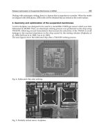
The responses of abutment backfill soil to the seismic load are very difficult to predict. The study
and tests revealed that the soil forces, which are applied to bridge abutment under seismic load,
mainly depend on the abutment movement direction and magnitude. In the design practice, the
Mononobe–Okabe method usually is used to quantify those loads for the abutment with no
restraints on the top. Recently, the “near full scale” abutment tests performed at the University of
California at Davis show a nonlinear relationship between the abutment displacement and the
D
C
=
+
+
15
40 1
05
.
.
© 2000 by CRC Press LLC
backfill soil reactions under certain seismic loading when the abutment moves toward its backfill
soil. This relation was plotted as shown in Figure 29.3. It is difficult to simulate this nonlinear
relationship between the abutment displacement and the backfill soil reactions while performing
bridge dynamic analysis. However, the tests concluded an upper limit for the backfill soil reaction
on the abutment. In design practice, a peak soil pressure acting on the abutment may be predicted
corresponding to certain abutment displacements. Based on the tests and investigations of past
earthquake damages, the California Transportation Department suggests guidelines for bridge anal-
ysis considering abutment damping behavior as follows.
By using the peak abutment force and the effective area of the mobilized soil wedge, the peak
soil pressure is compared to a maximum capacity of 7.7 ksf (0.3687 MPa). If the peak soil pressure
exceeds the soil capacity, the analysis should be repeated with reduced abutment stiffness. It is
important to note that the 7.7 ksf (0.3687 MPa) soil pressure is based on a reliable minimum
wall height of 8 ft (2.438 m). If the wall height is less than 8 ft (2.438 m), or if the wall is expected
to shear off at a depth below the roadway less than 8 ft (2.438 m), the allowable passive soil
pressure must be reduced by multiplying 7.7 ksf (0.3687 MPa) times the ratio of (
L
/8) [2], where
L
is the effective height of the abutment wall in feet. Furthermore, the shear capacity of the
abutment wall diaphragm (the structural member mobilizing the soil wedge) should be compared
with the demand shear forces to ensure the soil mobilizations. Abutment spring displacement is
then evaluated against an acceptable level of displacement of 0.2 ft (61 mm). For a monolithic-
type abutment this displacement is equal to the bridge superstructure displacement. For seat-
type abutments this displacement usually does not equal the bridge superstructure displacement,
which may include the gap between the bridge superstructure and abutment backwall. However,
a net displacement of about 0.2 ft (61 mm) at the abutment should not be exceeded. Field
investigations after the 1971 San Fernando earthquake revealed that the abutment, which moved
up to 0.2 ft (61 mm) in the longitudinal direction into the backfill soil, appeared to survive with
FIGURE 29.3
Proposed characteristics and experimental envelope for abutment backfill load–deformation.
© 2000 by CRC Press LLC
little need for repair. The abutments in which the backwall breaks off before other abutment
damage may also be satisfactory if a reasonable load path can be provided to adjacent bents and
no collapse potential is indicated.
For seismic loads in the transverse direction, the same general principles still apply. The 0.2-ft
(61-mm) displacement limit also applies in the transverse direction, if the abutment stiffness is
expected to be maintained. Usually, wingwalls are tied to the abutment to stiffen the bridge trans-
versely. The lateral resistance of the wingwall depends on the soil mass that may be mobilized by
the wingwall. For a wingwall with the soil sloped away from the exterior face, little lateral resistance
can be predicted. In order to increase the transverse resistance of the abutment, interior supple-
mental shear walls may be attached to the abutment or the wingwall thickness may be increased,
as shown in Figure 29.4. In some situations larger deflection may be satisfactory if a reasonable load
path can be provided to adjacent bents and no collapse potential is indicated. [2]
Based on the above guidelines, abutment analysis can be carried out more realistically by a trial-
and-error method on abutment soil springs. The criterion for abutment seismic resistance design
may be set as follows.
Monolithic Abutment or Diaphragm Abutment (Figure 29.5)
FIGURE 29.4
Abutment transverse enhancement.
© 2000 by CRC Press LLC
Seat-Type Abutment (Figure 29.6)
FIGURE 29.5
Seismic resistance elements for monolithic abutment.
© 2000 by CRC Press LLC
where
EQ
L
= longitudinal earthquake force from an elastic analysis
EQ
T
= transverse earthquake force from an elastic analysis
R
soil
= resistance of soil mobilized behind abutment
R
diaphragm
=
ϕ
times the nominal shear strength of the diaphragm
R
ww
=
ϕ
times the nominal shear strength of the wingwall
R
piles
=
ϕ
times the nominal shear strength of the piles
R
keys
=
ϕ
times the nominal shear strength of the keys in the direction of consideration
ϕ
= strength factor for seismic loading
µ
= coefficient factor between soil and concrete face at abutment bottom
It is noted that the purpose of applying a factor of 0.75 to the design of shear keys is to reduce the
possible damage to the abutment piles. For all transverse cases, if the design transverse earthquake
force exceeds the sum of the capacities of the wingwalls and piles, the transverse stiffness for the
analysis should equal zero (
EQ
T
= 0). Therefore, a released condition which usually results in larger
lateral forces at adjacent bents should be studied.
Responding to seismic load, bridges usually accommodate a large displacement. To provide
support at abutments for a bridge with large displacement, enough support width at the abutment
must be designed. The minimum abutment support width, as shown in Figure 29.7, may be equal
to the bridge displacement resulting from a seismic elastic analysis or be calculated as shown in
Equation (29-2), whichever is larger:
(29.2)
FIGURE 29.6
Seismic resistance elements for seat-type abutment.
NLHS=++ +(. )(.)305 2 5 10 1 0 002
2
© 2000 by CRC Press LLC
where
N
= support width (mm)
L
= length (m) of the bridge deck to the adjacent expansion joint, or to the end of bridge deck;
for single-span bridges
L
equals the length of the bridge deck
S
= angle of skew at abutment in degrees
H
= average height (m) of columns or piers supporting the bridge deck from the abutment to the
adjacent expansion joint, or to the end of the bridge deck;
H
= 0 for simple span bridges
29.2.4 Miscellaneous Design Considerations
Abutment Wingwall
Abutment wingwalls act as a retaining structure to prevent the abutment backfill soil and the
roadway soil from sliding transversely. Several types of wingwall for highway bridges are shown in
Figure 29.8. A wingwall design similar to the retaining wall design is presented in Section 29.3.
However, live-load surcharge needs to be considered in wingwall design. Table 29.2 lists the live-
load surcharge for different loading cases. Figure 29.9 shows the design loads for a conventional
cantilever wingwall. For seismic design, the criteria in transverse direction discussed in
Section 29.2.3 should be followed. Bridge wingwalls may be designed to sustain some damage in a
major earthquake, as long as bridge collapse is not predicted.
Abutment Drainage
A drainage system is usually provided for the abutment construction. The drainage system
embedded in the abutment backfill soil is designed to reduce the possible buildup of hydrostatic
pressure, to control erosion of the roadway embankment, and to reduce the possibility of soil
liquefaction during an earthquake. For a concrete-paved abutment slope, a drainage system also
needs to be provided under the pavement. The drainage system may include pervious materials,
PSP or PVC pipes, weep holes, etc. Figure 29.10 shows a typical drainage system for highway
bridge construction.
FIGURE 29.7
Abutment support width (seismic).
© 2000 by CRC Press LLC
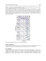
Abutment Slope Protection
Flow water scoring may severely damage bridge structures by washing out the bridge abutment
support soil. To reduce water scoring damage to the bridge abutment, pile support, rock slope
protection, concrete slope paving, and gunite cement slope paving may be used. Figure 29.11 shows
the actual design of rock slope protection and concrete slope paving protection for bridge abutments.
The stability of the rock and concrete slope protection should be considered in the design. An
enlarged block is usually designed at the toe of the protections.
Miscellaneous Details
Some details related to abutment design are given in Figure 29.12. Although they are only for regular
bridge construction situations, those details present valuable references for bridge designers.
FIGURE 29.8
Typical wingwalls.
TABLE 29.2
Live Load Surcharges for Wingwall Design
Highway truck loading 2 ft 0 in. (610 mm) equivalent soil
Rail loading E-60 7 ft 6 in. (2290 mm) equivalent soil
Rail loading E-70 8 ft 9 in. (2670 mm) equivalent soil
Rail loading E-80 10 ft 0 in. (3050 mm) equivalent soil
© 2000 by CRC Press LLC
29.2.5 Design Example
A prestressed concrete box-girder bridge with 5° skew is proposed overcrossing a busy freeway as
shown in Figure 29.13. Based on the roadway requirement, geotechnical information, and the details
mentioned above, an open-end, seat-type abutment is selected. The abutment in transverse direction
is 89 ft (27.13 m) wide. From the bridge analysis, the loads on abutment and bridge displacements
are as listed bellow:
FIGURE 29.9
Design loading for cantilever wingwall.
FIGURE 29.10
Typical abutment drainage system.
© 2000 by CRC Press LLC
Superstructure dead load = 1630 kips (7251 kN)
HS20 live load = 410 kips (1824 kN)
1.15 P-load + 1.0 HS load = 280 kips (1245 kN)
Longitudinal live load = 248 kips (1103 kN)
Longitudinal seismic load = 326 kips (1450 kN)
(bearing pad capacity)
Transverse seismic load = 1241 kips (5520 kN)
Bridge temperature displacement = 2.0 in. (75 mm)
Bridge seismic displacement = 6.5 in. (165 mm)
Geotechnical Information
Live-load surcharge = 2 ft (0.61 m)
Unit weight of backfill soil = 120 pcf (1922 kg/m
3
)
FIGURE 29.11
Typical abutment slope protections.
© 2000 by CRC Press LLC
Allowable soil bearing pressure = 4.0 ksf (0.19 MPa)
Soil lateral pressure coefficient (Ka) = 0.3
Friction coefficient = tan 33°
Soil liquefaction potential = very low
Ground acceleration = 0.3
g
Design Criteria
Abutment design Load factor method
Abutment stability Service load method
Design Assumptions
1. Superstructure vertical loading acting on the center line of abutment footing;
2. The soil passive pressure by the soil at abutment toe is neglected;
3. 1.0 feet (0.305 m) wide of abutment is used in the design;
4. reinforcement yield stress,
f
y
= 60000 psi (414 MPa)
5. concrete strength, = 3250 psi (22.41 MPa)
6. abutment backwall allowed damage in the design earthquake
FIGURE 29.12
Abutment design miscellaneous details.
FIGURE 29.13
Bridge elevation (example).
′
f
c
© 2000 by CRC Press LLC
Solution
1. Abutment Support Width Design
Applying Eq. (29.2) with
L
= 6.5 m
H
= 90.0 m
S
= 5°
the support width will be
N
= 600 mm. Add 75 mm required temperature movement, the
total required support width equals 675 mm. The required minimum support width for
seismic case equals the sum of the bridge seismic displacement, the bridge temperature
displacement, and the reserved edge displacement (usually 75 mm). In this example, this
requirement equals 315 mm, not in control. Based on the 675-mm minimum requirement,
the design uses 760 mm, OK. A preliminary abutment configuration is shown in Figure 29.14
based on the given information and calculated support width.
2. Abutment Stability Check
Figure 29.15 shows the abutment force diagram,
where
q
sc
= soil lateral pressure by live-load surcharge
q
e
= soil lateral pressure
q
eq
= soil lateral pressure by seismic load
P
DL
= superstructure dead load
P
HS
= HS20 live load
P
P
= permit live load
FIGURE 29.14
Abutment configuration (example).
© 2000 by CRC Press LLC
F
= longitudinal live load
F
eq
= longitudinal bridge seismic load
P
ac
= resultant of active seismic soil lateral pressure
h
sc
= height of live-load surcharge
γ
= unit weight of soil
W
i
= weight of abutment component and soil block
q
sc
=
k
a
×
γ
×
h
sc
= 0.3
×
0.12
×
2 = 0.072 ksf (0.0034 MPa)
q
e
=
k
a
×
γ
×
H
= 0.3
×
0.12
×
15.5 = 0.558 ksf (0.0267 MPa)
q
eq
= k
ae
× γ × H = 0.032 × 0.12 × 15.5 = 0.06 ksf (0.003 MPa)
The calculated vertical loads, lateral loads, and moment about point A are listed in Table 29.3.
The maximum and minimum soil pressure at abutment footing are calculated by
(29.3)
where
p = soil bearing pressure
P = resultant of vertical forces
B = abutment footing width
e = eccentricity of resultant of forces and the center of footing
(29.4)
M = total moment to point A
Referring to the Table 29.1 and Eqs. (29.3) and (29.4) the maximum and minimum soil
pressures under footing corresponding to different load cases are calculated as
Since the soil bearing pressures are less than the allowable soil bearing pressure, the soil
bearing stability is OK.
FIGURE 29.15 Abutment applying forces diagram (example).
p
P
B
e
B
=±
1
6
eB
M
P
=−2
© 2000 by CRC Press LLC
Check for the stability resisting the overturning (load case III and IV control):
Checking for the stability resisting the sliding (load case III and IV control)
Since the structure lateral dynamic force is only combined with dead load and static soil
lateral pressures, and the factor of safety FS = 1.0 can be used, the seismic case is not in control.
3. Abutment Backwall and Stem Design
Referring to AASHTO guidelines for load combinations, the maximum factored loads for
abutment backwall and stem are
Load Case
p
max
p
min
p
allowable
with Allowable % of Overstress
Evaluate
I 3.81 3.10 4.00 OK
II 3.42 2.72 4.00 OK
III 1.84 1.22 6.00 OK
IV 4.86 2.15 5.00 OK
V 2.79 1.93 6.00 OK
Seismic 6.73 0.54 8.00 OK
TABLE 29.3 Vertical Forces, Lateral Forces, and Moment about
Point A (Example)
Vertical Lateral
Load Load Load Arm to A Moment to A
Description (kips) (kips) (ft) (k-ft)
Backwall W
1
0.94
—
7.75 7.28
Stem W
2
3.54
—
6.00 23.01
Footing W
3
4.50
—
6.00 27.00
Backfill soil 5.85 — 10.13 59.23
— 4.33 5.17 –22.34
Soil surcharge — 1.16 7.75 –8.65
Front soil W
4
1.71
—
2.38 4.06
Wingwalls 0.85 — 16.12 13.70
Keys 0.17 — 6.00 1.04
P
DL
18.31
—
6.00 110.00
P
HS
4.61
—
6.00 27.64
P
P
3.15
—
6.00 18.90
F — 2.79 9.25 –25.80
F
eq
—
3.66 9.25 –33.90
Soil seismic load — 0.47 9.30 –4.37
Load Case Driving Moment Resist Moment Factor of Safety Evaluate
III 31 133.55 4.3 OK
IV 56.8 262.45 4.62 OK
Load Case Driving Force Resist Force Factor of Safety Evaluation
III 5.44 11.91 2.18 OK
IV 8.23 20.7 3.26 OK
Location V (kips) M (k-ft)
Backwall level 1.95 4.67
Bottom of stem 10.36 74.85
© 2000 by CRC Press LLC
Abutment Backwall
Try #5 at 12 in. (305 mm) with 2 in. (50 mm) clearance
d = 9.7 in. (245 mm)
OK
OK
No shear reinforcement needed.
Abutment Stem
Abutment stem could be designed based on the applying moment variations along the
abutment wall height. Here only the section at the bottom of stem is designed.
Try #6 at 12 in. (305 mm) with 2 in. (50 mm) clearance.
d = 39.4 in. (1000 mm)
OK
OK
No shear reinforcement needed.
4. Abutment Footing Design
Considering all load combinations and seismic loading cases, the soil bearing pressure dia-
gram under the abutment footing are shown in Figure 29.16.
Af
sy
×= ×× =
()
031 60
12
16
13 95. . kips 62.05 kN
a
Af
fb
sy
cw
=
⋅
⋅
′
⋅
=
()()
()
=
()
φ
13 95
0 85 3 25 12
042 1067
.
in. mm
MMAfd
a
unsy
=⋅ =⋅ ⋅ −
=× × −
=⋅ ⋅
()
>⋅ ⋅
()
φφ
2
0 9 13 95 9 7
042
2
933 1346
467 633
.
.
k ft kN m
k ft kN m
Vfbd
ccw
=
′
⋅⋅=× ×× =2 2 3250 12 9 7 13 27 59 03 (. kips kN)
VV
uc
=⋅ = × =
()
>
()
φ 085 1327 1128 5017 195 . .kip kN kips 8.67 kN
Af
sy
×= ×=0 44 60 26 40 117 43 (.)kips kN
a
Af
fb
sy
cw
=
⋅
⋅
′
⋅
==
φ
26 4
0 85 3 25 12
0 796
.
(. )(. )( )
. in (20.0 mm)
MAfd
a
usy
=⋅ ⋅ −
=× × −
=⋅ ⋅
>⋅ ⋅
φ
2
09 264 394
08
2
77 22
74 85
.
.
.
.
k ft (104.7kN m)
k ft (101.5kN m)
Vfbd
ccw
=
′
=× × × =2 2 3250 12 39 4 53 91. . kips (238 kN)
VV
uc
=⋅ = × = >φ 085 5391 4581. . . kips (202.3 kN) 10.36 kips (46.08 kN)
© 2000 by CRC Press LLC
a. Design forces:
Section at front face of abutment stem (design for flexural reinforcement):
q
a-a
= 5.1263 ksf (0.2454 MPa)
M
a-a
= 69.4 k-ft (94.1 kN·m)
Section at d = 30 – 3 – 1 = 26 in. (660 mm) from the front face of abutment stem (design
for shear reinforcement):
q
b-b
= 5.2341 ksf (0.251 MPa)
V
b-b
= 15.4 kips (68.5 kN)
b. Design flexural reinforcing (footing bottom):
Try #8 at 12, with 3 in. (75 mm) clearance at bottom
d = 30 – 3 – 1 = 26 in. (660 mm)
OK
FIGURE 29.16 Bearing pressure under abutment footing (example).
Af
sy
×= ×=079 60 474 )kips (211kN
a
Af
fb
sy
cw
=
⋅
⋅
′
⋅
==
φ
47 4
0 85 3 25 12
143 36
.
(. )(. )( )
.()in. mm
MAfd
a
nsy
=⋅ ⋅ −
=× × −
=⋅ ⋅
>⋅ ⋅
φ
2
09 474 26
143
2
89 9 121 89
69 4 94 1
.
.(. )
.(.)
kft kNm
kft kNm
© 2000 by CRC Press LLC
OK
No shear reinforcement needed.
Since the minimum soil bearing pressure under the footing is in compression, the
tension at the footing top is not the case. However, the minimum temperature reinforcing,
0.308 in.
2
/ft (652 mm
2
/m) needs to be provided. Using #5 at 12 in. (305 mm) at the footing
top yields
A
s
= 0.31 in.
2
/ft, (656 mm
2
/m) OK
5. Abutment Wingwall Design
The geometry of wingwall is
h = 3.0 ft (915 mm); S = 2.0 ft (610 mm);
H = 13.0 ft (3960 mm); L = 18.25 ft (5565 mm)
Referring to the Figure 29.15, the design loads are
Design flexural reinforcing. Try using # 8 at 9 (225 mm).
d = 12 – 2 – 0.5 = 9.5 in. (240 mm)
Vfbd
ccw
=
′
⋅⋅=× ×× =2 2 3250 12 26 35 57. kips (158.24 kN)
VV
uc
=⋅ = × = >φ 085 3557 3023. . . kips (134.5 kN) 15.5 kips (68.5 kN)
V
wL
HhHhS
AA−
=++
()
+
()
[]
=
×
++
()
+×
()
[]
=
6
3
036 1825
6
13 3 13 3 3 2 34
2
2
)kips (152.39 kN
M
wL
hHSHh
AA−
=++
()
+
()
[]
=
×
()
++×
()
+×
()
[]
=⋅ ⋅
2
24
342
0 036 18 25
24
3 3 13 4 2 12 2 3 212 8
2
2
2
. k ft (3129 kN m)
Af
sy
×=× × × = 13 (0.79) 60 kips (3682 kN
12
9
821 6.)
a
Af
fb
sy
cw
=
⋅
⋅
′
⋅
==
φ
1280
0 85 3 25 13 12
297
(. )(. )( )( )
. in. (75 mm)
M
n
A
s
f
y
d
a
.
=⋅ ⋅ −
=× × −
=⋅ ⋅
>⋅ ⋅
φ
2
0 9 821 6 9 5
297
2
493 8
212
.(.)
.
. k ft (7261 kN m)
.8 k ft (3129 kN m)
© 2000 by CRC Press LLC
Checking for shear
OK
No shear reinforcing needed.
Since the wingwall is allowed to be broken off in a major earthquake, the adjacent bridge
columns have to be designed to sustain the seismic loading with no wingwall resistance. The
abutment section, footing, and wingwall reinforcing details are shown in Figures 29.17a and b.
FIGURE 29.17 (a) Abutment typical section design (example). (b) Wingwall reinforcing (example).
Vfbd
ccw
=
′
⋅⋅=× ××× =2 2 3250 13 12 9 5 1. 68 kips (757.3 kN)
V V .
uc
=⋅= × = >ϕ 0 85 168 142 34 kips (636 kN kips (152.3kN))
FIGURE 29.18 Retaining wall types.
© 2000 by CRC Press LLC
© 2000 by CRC Press LLC
29.3 Retaining Structures
29.3.1 Retaining Structure Types
The retaining structure, or, more specifically, the earth-retaining structure, is commonly required
in a bridge design project. It is common practice that the bridge abutment itself is used as a retaining
structure. The cantilever wall, tieback wall, soil nail wall and mechanically stabilized embankment
(MSE) wall are the most frequently used retaining structure types. The major design function of a
retaining structure is to resist lateral forces.
The cantilever retaining wall is a cantilever structure used to resist the active soil pressure in
topography fill locations. Usually, the cantilever earth-retaining structure does not exceed 10 m in
height. Some typical cantilever retaining wall sections are shown in Figure 29.18a.
The tieback wall can be used for topography cutting locations. High-strength tie strands are
extended into the stable zone and act as anchors for the wall face elements. The tieback wall can
be designed to have minimum lateral deflection. Figure 29.18d shows a tieback wall section.
The MSE wall is a kind of “reinforced earth-retaining” structure. By installing multiple layers of
high-strength fibers inside of the fill section, the lateral deflection of filled soil will be restricted.
There is no height limit for an MSE wall but the lateral deflection at the top of the wall needs to
be considered. Figure 29.18e shows an example of an MSE wall.
The soil nail wall looks like a tieback wall but works like an MSE wall. It uses a series of soil nails
built inside the soil body that resist the soil body lateral movement in the cut sections. Usually, the
soil nails are constructed by pumping cement grout into predrilled holes. The nails bind the soil
together and act as a gravity soil wall. A typical soil nail wall model is shown in Figure 29.18f.
29.3.2 Design Criteria
Minimum Requirements
All retaining structures must be safe from vertical settlement. They must have sufficient resistance
against overturning and sliding. Retaining structures must also have adequate strength for all
structural components.
1. Bearing capacity: Similar to any footing design, the bearing capacity factor of safety should
be ≥1.0. Table 29.4 is a list of approximate bearing capacity values for some common mate-
rials. If a pile footing is used, the soil-bearing capacity between piles is not considered.
2. Overturning resistance: The overturning point of a typical retaining structure is located at the
edge of the footing toe. The overturning factor of safety should be ≥1.50. If the retaining
structure has a pile footing, the fixity of the footing will depend on the piles only.
3. Sliding resistance: The factor of safety for sliding should be ≥1.50. The typical retaining wall
sliding capacity may include both the passive soil pressure at the toe face of the footing and
the friction forces at the bottom of the footing. In most cases, friction factors of 0.3 and 0.4
TABLE 29.4 Bearing Capacity
Bearing Capacity [N]
Material min, kPa max, kPa
Alluvial soils 24 48
Clay 48 190
Sand, confined 48 190
Gravel 95 190
Cemented sand and gravel 240 480
Rock 240 —
© 2000 by CRC Press LLC
can be used for clay and sand, respectively. If battered piles are used for sliding resistance,
the friction force at the bottom of the footing should be neglected.
4. Structural strength: Structural section moment and shear capacities should be designed
following common strength factors of safety design procedures.
Figure 29.19 shows typical loads for cantilever retaining structure design.
Lateral Load
The unit weight of soil is typically in the range of 1.5
to 2.0 ton/m
3
. For flat backfill cases, if the
backfill material is dry, cohesionless sand, the lateral earth pressure (Figure 29.20a) distribution on
the wall will be as follows
The active force per unit length of wall (Pa) at bottom of wall can be determined as
p
a
= k
a
γ H (29.5)
The passive force per unit length of wall (Pa) at bottom of wall can be determined as
p
p
= k
p
γ H (29.6)
where
H = the height of the wall (from top of the wall to bottom of the footing)
γ = unit weight of the backfill material
k
a
= active earth pressure coefficient
k
p
= passive earth pressure coefficient
The coefficients k
a
and k
p
should be determined by a geologist using laboratory test data from a
proper soil sample. The general formula is
FIGURE 29 19 Typical loads on retaining wall.