Steel Bridge Construction-3 pps
Bạn đang xem bản rút gọn của tài liệu. Xem và tải ngay bản đầy đủ của tài liệu tại đây (4.98 MB, 12 trang )
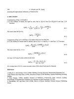
Durkee, J. “Steel Bridge Construction”
Bridge Engineering Handbook.
Ed. Wai-Fah Chen and Lian Duan
Boca Raton: CRC Press, 2000
© 2000 by CRC Press LLC
Figure 45.26a Erection of individual wire loops.
Figure 45.26b Adjustment of individual wire loops.
Figure 45.26 Cable-spinning procedure for constructing suspension bridge-parallel-wire main cables, showing
details of aerial spinning method for forming individual 5 mm wires into strands containing 400 to 500 wires. Each
wire loop is erected as shown in Figure 45.26a (refer to Figure 45.25), then adjusted to the correct sag as shown in
Figure 45.26b. Each completed strand is banded with tape, then adjusted to the correct sag in each span. With all
strands in place, they are compacted to form a solid round homogeneous mass of wires. The aerial spinning method
was developed by John Roebling in the mid-19th century.
© 2000 by CRC Press LLC
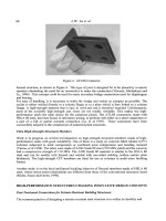
Figure 45.27 Erection of suspended deck steelwork, second Tacoma Narrows Bridge, Washington, 1950. The
Chicago boom on the tower raises deck steelwork components to deck level, where they are transported to deck
travelers by material cars. Each truss double panel is connected at top-chord level to previously erected trusses, and
left open at bottom-chord level to permit temporary upward deck curvature, which results from the partial loading
condition of the main suspension cables. The main span (at right) is 2800 ft (853 m), and side spans are 100 ft (335
m). The stiffening trusses are 33 ft (10 m) deep and 60 ft (18 m) on centers. Tower-base kneebraces (see Figure
45.24) show clearly here.
Figure 45.28 Moving deck traveler forward, second Tacoma Narrows Bridge, Washington, 1950. The traveler
pulling-falls leadline passes around the sheave beams at the forward end of the stringers, and is attached to the front
of the material car (at left). The material car is pulled back toward the tower, advancing the traveler two panels to
its new position at the end of the deck steelwork. Arrows show successive positions of material car. (a) Traveler at
star of move, (b) traveler advanced one panel, and (c) traveler at end of move.
© 2000 by CRC Press LLC
Figure 45.29 Erecting closing girder sections of Passaic River Bridge, New Jersey Turnpike, 1951. Huge double-
boom travelers, each weighing 270 tons, erect closing plate girders of the 375 ft (114 m) main span. The closing
girders are 14 ft (4.3 m) deep and 115 ft (35 m) long and weigh 146 tons each. Sidewise entry was required (as
shown) because of long projecting splice material. Longitudinal motion was provided at one pier, where girders
were jacked to effect closure. Closing girders were laterally stable without floor steel fill-in, such that derrick falls
could be released immediately. (Courtesy of Bethlehem Steel Corporation.)
© 2000 by CRC Press LLC
Figure 45.30 Floating-in erection of a truss span, first Chesapeake Bay Bridge, Maryland, 1951. Erected 300 ft
(91 m) deck-truss spans form erection dock, providing a work platform for two derrick travelers. A permanent
deck-truss span serves as a falsework truss supported on barges and is shown carrying the 470 ft (143 m) anchor
arm of the through-cantilever truss. This span is floated to its permanent position, then landed onto its piers by
ballasting the barges. (a) Float leaves erection dock, and (b) float arrives at permanent position. (Courtesy of
Bethlehem Steel Corporation.)
Figure 45.31 Floating-in erection of a truss span, first Chesapeake Bay Bridge, Maryland, 1952. A 480 ft (146 m)
truss span, weighting 850 tons, supported on falsework consisting of a permanent deck-truss span along with
temporary members, is being floated-in for landing onto its piers. Suspension bridge cables are under construction
in background. (Courtesy of Bethlehem Steel Corporation.)
© 2000 by CRC Press LLC
Figure 45.32 Erection of a truss span by hoisting, first Chesapeake Bay Bridge, Maryland, 1952. A 360 ft (110 m)
truss span is floated into position on barges and picked clear using four sets of lifting falls. Suspension bridge deck
is under construction at right. (Courtesy of Bethlehem Steel Corporation.)
© 2000 by CRC Press LLC
Figure 45.33 Erection of suspension bridge deck structure, first Chesapeake Bay Bridge, Maryland, 1952. A typical
four-panel through-truss deck section, weighting 99 tons, has been picked from the barge and is being raised into
position using four sets of lifting falls attached to main suspension cables. The closing deck section is on the barge,
ready to go up next. (Courtesy of Bethlehem Steel Corporation.)
Figure 45.34 Greater New Orleans cantilever bridge, Louisiana, 1957. Tall double-boom deck travelers started at
ends of main bridge and erected anchor spans on falsework, then the 1575 ft (480 m) main span by cantilevering
to midspan. (Courtesy of Bethlehem Steel Corporation.)
© 2000 by CRC Press LLC
Figure 45.35 Tower erection, second Delaware Memorial Bridge, Wilmington, Del., 1966. The tower erection
traveler has reached the topmost erecting position and swings into place the 23 ton closing top-strut section. The
tower legs were jacked apart about 2 in (50 mm) to provide entering clearance. The traveler jumping beams are in
the topmost working position, above the cable saddles. The tower steelwork is about 418 ft (127 m) high. Cable
anchorage pier is under construction at right. First Delaware Memorial Bridge (1951) is at left. The main span of
both bridges is 2150 ft (655 m). (Courtesy of Bethlehem Steel Corporation.)
© 2000 by CRC Press LLC
Figure 45.36 Erecting orthotropic-plate decking panel, Poplar Street Bridge, St. Louis, Mo., 1967. A five-span, 2165
ft (660 m) continuous box-girder bridge, main span 600 ft (183 m). Projecting box ribs are 5 1/2 × 17 ft (1.7 × 5.2
m) in cross-section, and decking section is 27 × 50 ft (8.2 × 15.2 m). Decking sections were field welded, while all
other connections were field bolted. Box girders are cantilevered to falsework bents using overhead “positioning
travelers” (triangular structure just visible above deck at left) for intermediate support. (Courtesy of Bethlehem Steel
Corporation.)
© 2000 by CRC Press LLC
Figure 45.37 Erection of parallel-wire-stand (PWS) cables, the Newport Bridge suspension spans, Narragansett
Bay, R.I., 1968. Bridge engineering history was made at Newport with the development and application of shop-
fabricated parallel-wire socketed strands for suspension bridge cables. Each Newport cable was formed of seventy-
six 61-wire PWS, each 4512 ft (1375 m) long and weighing 15 tons. Individual wires are 0.202 in. (5.13 mm) in
diameter and are zinc coated. Parallel-wire cables can be constructed of PWS faster and at lower cost than by
traditional air spinning of individual wires (see Figures 45.25 and 45.26). (Courtesy of Bethlehem Steel Corporation.)
Figure 45.37a Aerial tramway tows PWS from west anchorage up side span, then on across other spans to east
anchorage. Strands are about 1 3/4 in (44 mm) in diameter.
© 2000 by CRC Press LLC
Figure 45.37b Cable formers maintain strand alignment in cables prior to cable compaction. Each finished cable
is about 15-1/4 in .(387 mm) in diameter. (Courtesy of Bethlehem Steel Corporation.)
© 2000 by CRC Press LLC
Figure 45.38 Pipe-type anchorage for parallel-wire-strand (PWS) cables, the Newport Bridge suspension spans,
Narragansett Bay, R.I., 1967. Pipe anchorages shown will be embedded in anchorage concrete. The socketed end of
each PWS is pulled down its pipe from the upper end, then seated and shim-adjusted against the heavy bearing
plate at the lower end. The pipe-type anchorage is much simpler and less costly than the standard anchor-bar type
used with aerial-spun parallel-wire cables (see Figure 45.25b). (Courtesy of Bethlehem Steel Corporation.)