Construction of Marine and offshore structures pot
Bạn đang xem bản rút gọn của tài liệu. Xem và tải ngay bản đầy đủ của tài liệu tại đây (16.13 MB, 795 trang )
q 2007 by Taylor & Francis Group, LLC
q 2007 by Taylor & Francis Group, LLC
To the great pioneers in Marine and Offshore Construction who were
undeterred by violent storms and massive ice.
q 2007 by Taylor & Francis Group, LLC
Preface
This third editon has been intensively augmented and revised to include the latest
developments in this rapidly expanding field. The intensified search for oil and gas, the
catastrophic flooding of coastal regions and the demands for transportation, bridges, sub-
merged tunnels and waterways have led to the continuing innovation of new technology
which is nowavailable for use on more conventional projects as well as those at the frontiers.
This text is intended as a guide and reference for practicing engineers and constructors
for use in the marine environment. It is also intended as a text for graduate engineering
students interested in this highly challenging endeavour.
q 2007 by Taylor & Francis Group, LLC
Acknowledgments
I wish to acknowledge the help of many members of our company, Ben C. Gerwick, Inc.
making available information on the current construction of marine and offshore projects,
also the willing responses to my queries from other sources in the industry.
I would like to thank my administrative assistant, Michelle Yu, for her word-processing
of the manuscript.
q 2007 by Taylor & Francis Group, LLC
Author
Ben C. Gerwick, Jr. is the author of Construction of Prestressed Concrete, first, second, and
third editions, and the first and second editions of Construction of Marine and Offshore
Structures.
He was born in Berkeley, California, in 1919. He received his B.S. in civil engineering
from the University of California at Berkeley in 1940. He joined the U.S. Navy the same
year and served until 1946. He was assigned as commanding officer of the USS Scania
(AK 40) in 1945.
He has worked in marine and offshore construction, or taught about it, for most of the
time since his discharge from the navy. He worked in Marine Construction from 1946 to
1967 and from 1967 to 1971 in Offshore Construction, ending as President of Ben C.
Gerwick, Inc., and Manager of Offshore Construction for Santa Fe International. From
1971 to 1989, he served as Professor of Civil Engineering at the University of California,
Berkeley.
He is a member of the National Academy of Engineering, the National Academy of
Construction, and an honorary member of the American Society of Civil Engineers, which
awarded him their Outstanding Engineering Lifetime Achievement Award in 2002.
He has been named a fellow of the International Association of Structural and Bridge
Engineers and has served as president of the International Federation of Prestressing.
He was awarded the Berkeley Fellow Medal in 1989.
q 2007 by Taylor & Francis Group, LLC
Contents
Introduction
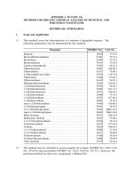
0.1 General 1
0.2 Geography 3
0.3 Ecological Environment 4
0.4 Legal Jurisdiction 4
0.5 Offshore Construction Relationships and Sequences 5
0.6 Typical Marine Structures and Contracts 8
0.7 Interaction of Design and Construction 9
Chapter 1 Physical Environmental Aspects of Marine and
Offshore Construction
1.1 General 15
1.2 Distances and Depths 15
1.3 Hydrostatic Pressure and Buoyancy 16
1.4 Temperature 17
1.5 Seawater and Sea–Air Interface Chemistry 18
1.5.1 Marine Organisms 18
1.6 Currents 20
1.7 Waves and Swells 25
1.8 Winds and Storms 31
1.9 Tides and Storm Surges 34
1.10 Rain, Snow, Fog, Spray, Atmospheric Icing, and Lightning 36
1.11 Sea Ice and Icebergs 37
1.12 Seismicity, Seaquakes, and Tsunamis 42
1.13 Floods 43
1.14 Scour 44
1.15 Siltation and Bed Loads 44
1.16 Sabotage and Terrorism 45
1.17 Ship Traffic 45
1.18 Fire and Smoke 46
1.19 Accidental Events 46
1.20 Global Warming 47
Chapter 2 Geotechnical Aspects: Seafloor and Marine Soils
2.1 General 49
2.2 Dense Sands 52
2.3 Liquefaction of Soils 52
2.4 Calcareous Sands 53
2.5 Glacial Till and Boulders on Seafloor 53
2.6 Overconsolidated Silts 54
2.7 Subsea Permafrost and Clathrates 55
q 2007 by Taylor & Francis Group, LLC
2.8 Weak Arctic Silts and Clays 55
2.9 Ice Scour and Pingos 56
2.10 Methane Gas 56
2.11 Muds and Clays 56
2.11.1 Underwater Slopes in Clays 57
2.11.2 Pile Driving “Set-Up” 58
2.11.3 Short-Term Bearing Strength 58
2.11.4 Dredging 58
2.11.5 Sampling 58
2.11.6 Penetration 59
2.11.7 Consolidation of Clays; Improvement in Strength 59
2.12 Coral and Similar Biogenic Soils; Cemented Soils, Cap Rock 59
2.13 Unconsolidated Sands 60
2.14 Underwater Sand Dunes (“Megadunes”) 62
2.15 Bedrock Outcrops 62
2.16 Cobbles 63
2.17 Deep Gravel Deposits 64
2.18 Seafloor Oozes 64
2.19 Seafloor Instability and Slumping; Turbidity Currents 64
2.20 Scour and Erosion 65
2.21 Concluding Remarks 66
Chapter 3 Ecological and Societal Impacts of Marine Construction
3.1 General 69
3.2 Oil and Petroleum Products 69
3.3 Toxic Chemicals 70
3.4 Contaminated Soils 71
3.5 Construction Wastes 71
3.6 Turbidity 71
3.7 Sediment Transport, Scour, and Erosion 72
3.8 Air Pollution 72
3.9 Marine Life: Mammals and Birds, Fish, and Other Biota 73
3.10 Aquifers 74
3.11 Noise 74
3.12 Highway, Rail, Barge, and Air Traffic 75
3.13 Protection of Existing Structures 75
3.14 Liquefaction 77
3.15 Safety of the Public and Third-Party Vessels 77
3.16 Archaeological Concerns 78
Chapter 4 Materials and Fabrication for Marine Structures
4.1 General 79
4.2 Steel Structures for the Marine Environment 79
4.2.1 Steel Materials 80
4.2.2 Fabrication and Welding 80
4.2.3 Erection of Structural Steel 85
4.2.4 Coatings and Corrosion Protection of Steel Structures 88
4.2.5 High Performance Steels 91
4.3 Structural Concrete 91
q 2007 by Taylor & Francis Group, LLC
4.3.1 General 91
4.3.2 Concrete Mixes and Properties 91
4.3.2.1 High Performance Concrete— “Flowing Concrete” 95
4.3.2.2 Structural Low-Density Concrete 96
4.3.2.3 Ultra-High Performance Concrete (UHPC) 97
4.3.3 Conveyance and Placement of Concrete 97
4.3.4 Curing 98
4.3.5 Steel Reinforcement 98
4.3.6 Prestressing Tendons and Accessories 102
4.3.7 Embedments 105
4.3.8 Coatings for Marine Concrete 106
4.3.9 Construction Joints 106
4.3.10 Forming and Support 107
4.3.11 Tolerances 108
4.4 Hybrid Steel–Concrete Structures 108
4.4.1 Hybrid Structures 109
4.4.2 Composite Construction 109
4.5 Plastics and Synthetic Materials, Composites 111
4.6 Titanium 113
4.7 Rock, Sand, and Asphaltic-Bituminous Materials 114
Chapter 5 Marine and Offshore Construction Equipment
5.1 General 117
5.2 Basic Motions in a Seaway 118
5.3 Buoyancy, Draft, and Freeboard 120
5.4 Stability 121
5.5 Damage Control 124
5.6 Barges 126
5.7 Crane Barges 130
5.8 Offshore Derrick Barges (Fully Revolving) 134
5.9 Semisubmersible Barges 137
5.10 Jack-Up Construction Barges 140
5.11 Launch Barges 144
5.12 Catamaran Barges 146
5.13 Dredges 147
5.14 Pipe-Laying Barges 152
5.15 Supply Boats 155
5.16 Anchor-Handling Boats 156
5.17 Towboats 156
5.18 Drilling Vessels 157
5.19 Crew Boats 158
5.20 Floating Concrete Plant 158
5.21 Tower Cranes 159
5.22 Specialized Equipment 160
Chapter 6 Marine Operations
6.1 Towing 161
6.2 Moorings and Anchors 169
6.2.1 Mooring Lines 169
q 2007 by Taylor & Francis Group, LLC
6.2.2 Anchors 170
6.2.2.1 Drag Anchors 170
6.2.2.2 Pile Anchors 174
6.2.2.3 Propellant Anchors 174
6.2.2.4 Suction Anchors 175
6.2.2.5 Driven-Plate Anchors 175
6.2.3 Mooring Systems 175
6.3 Handling Heavy Loads at Sea 183
6.3.1 General 183
6.4 Personnel Transfer at Sea 190
6.5 Underwater Intervention, Diving, Underwater Work Systems,
Remote-Operated Vehicles (ROVs), and Manipulators 194
6.5.1 Diving 194
6.5.2 Remote-Operated Vehicles (ROVs) 201
6.5.3 Manipulators 203
6.6 Underwater Concreting and Grouting 203
6.6.1 General 203
6.6.2 Underwater Concrete Mixes 204
6.6.3 Placement of Tremie Concrete 205
6.6.4 Special Admixtures for Concreting Underwater 209
6.6.5 Grout-Intruded Aggregate 212
6.6.6 Pumped Concrete and Mortar 213
6.6.7 Underbase Grout 213
6.6.8 Grout for Transfer of Forces from Piles to Sleeves and
Jacket Legs 215
6.6.9 Low-Strength Underwater Concrete 215
6.6.10 Summary 215
6.7 Offshore Surveying, Navigation, and Seafloor Surveys 216
6.8 Temporary Buoyancy Augmentation 223
Chapter 7 Seafloor Modifications and Improvements
7.1 General 225
7.2 Controls for Grade and Position 226
7.2.1 Determination of Existing Conditions 226
7.3 Seafloor Dredging, Obstruction Removal, and Leveling 227
7.4 Dredging and Removal of Hard Material and Rock 235
7.5 Placement of Underwater Fills 240
7.6 Consolidation and Strengthening of Weak Soils 245
7.7 Prevention of Liquefaction 248
7.8 Scour Protection 248
7.9 Concluding Remarks 252
Chapter 8 Installation of Piles in Marine and Offshore Structure
8.1 General 255
8.2 Fabrication of Tubular Steel Piles 259
8.3 Transportation of Piling 260
8.4 Installing Piles 262
8.5 Methods of Increasing Penetration 285
8.6 Insert Piles 290
q 2007 by Taylor & Francis Group, LLC
8.7 Anchoring into Rock or Hardpan 291
8.8 Testing High Capacity Piles 292
8.9 Steel H Piles 293
8.10 Enhancing Stiffness and Capacity of Piles 293
8.11 Prestressed Concrete Cylinder Piles 294
8.12 Handling and Positioning of Piles for Offshore Terminals 296
8.13 Drilled and Grouted Piles 297
8.14 Cast-in-Drilled-Hole Piles, Drilled Shafts 302
8.15 Other Installation Experience 312
8.16 Installation in Difficult Soils 312
8.17 Other Methods of Improving the Capacity of Driven Piles 313
8.18 Slurry Walls, Secant Walls, and Tangent Walls 315
8.19 Steel Sheet Piles 316
8.20 Vibratory Pile Hammers 317
8.21 Micropiles 317
Chapter 9 Harbor, River, and Estuary Structures
9.1 General 319
9.2 Harbor Structures 319
9.2.1 Types 319
9.2.2 Pile-Supported Structures 319
9.2.2.1 Steel Piles 319
9.2.2.2 Concrete Piles 320
9.2.2.3 Installation 320
9.2.2.4 Batter (Raker) Piles 322
9.2.2.5 Pile Location 323
9.2.2.6 Jetting 323
9.2.2.7 Driving Through Obstructions or Very Hard Material 323
9.2.2.8 Staying of Piles 324
9.2.2.9 Head Connections 325
9.2.2.10 Concrete Deck 326
9.2.2.11 Fender System 327
9.2.3 Bulkheads, Quay Walls 327
9.2.3.1 Description 327
9.2.3.2 Sheet Pile Bulkheads 327
9.2.3.3 Caisson Quay Walls 330
9.3 River Structures 331
9.3.1 Description 331
9.3.2 Sheet Pile Cellular Structures 331
9.3.3 “Lift-In” Precast Concrete Shells—“In-the-Wet” Construction 335
9.3.4 Float-In Concrete Structures 336
9.3.4.1 General 336
9.3.4.2 Prefabrication 337
9.3.4.3 Launching 338
9.3.4.4 Installation 339
9.3.4.5 Leveling Pads 339
9.3.4.6 Underfill 340
9.4 Foundations for Overwater Bridge Piers 343
9.4.1 General 343
9.4.2 Open Caissons 344
q 2007 by Taylor & Francis Group, LLC
9.4.3 Pneumatic Caissons 345
9.4.4 Gravity-Base Caissons (Box Caissons) 346
9.4.5 Pile-Supported Box Caissons 357
9.4.6 Large-Diameter Tubular Piles 360
9.4.6.1 Steel Tubular Piles 360
9.4.6.2 Prestressed Concrete Tubular Piles 367
9.4.7 Connection of Piles to Footing Block (Pile Cap) 370
9.4.8 CIDH Drilled Shafts (Piles) 371
9.4.9 Cofferdams 371
9.4.9.1 Steel Sheet Pile Cofferdams 372
9.4.9.2 Liquefaction During Cofferdam Construction 375
9.4.9.3 Cofferdams on Slope 376
9.4.9.4 Deep Cofferdams 376
9.4.9.5 Portable Cofferdams 378
9.4.10 Protective Structures for Bridge Piers 378
9.4.11 Belled Piers 379
9.5 Submerged Prefabricated Tunnels (Tubes) 381
9.5.1 Description 381
9.5.2 Prefabrication of Steel–Concrete Composite Tunnel Segments 382
9.5.3 Prefabrication of All-Concrete Tube Segments 383
9.5.4 Preparation of Trench 384
9.5.5 Installing the Segments 385
9.5.6 Underfill and Backfill 386
9.5.7 Portal Connections 386
9.5.8 Pile-Supported Tunnels 386
9.5.9 Submerged Floating Tunnels 387
9.6 Storm Surge Barriers 387
9.6.1 Description 387
9.6.2 Venice Storm Surge Barrier 388
9.6.3 Oosterschelde Storm Surge Barrier 389
9.7 Flow-Control Structures 397
9.7.1 Description 397
9.7.2 Temperature Control Devices 397
Chapter 10 Coastal Structures
10.1 General 399
10.2 Ocean Outfalls and Intakes 399
10.3 Breakwaters 408
10.3.1 General 408
10.3.2 Rubble-Mound Breakwaters 408
10.3.3 Caisson-Type Breakwaters and Caisson-Retained Islands 414
10.3.4 Sheet Pile Cellular Breakwaters 415
10.4 Offshore Terminals 416
Chapter 11 Offshore Platforms: Steel Jackets and Pin Piles
11.1 General 433
11.2 Fabrication of Steel Jackets 434
11.3 Load-Out, Tie-Down, and Transport 435
11.4 Removal of Jacket from Transport Barge; Lifting; Launching 444
q 2007 by Taylor & Francis Group, LLC
11.5 Upending of Jacket 452
11.6 Installation on the Seafloor 455
11.7 Pile and Conductor Installation 458
11.8 Deck Installation 461
11.9 Examples 464
11.9.1 Example 1—Hondo 464
11.9.2 Example 2—Cognac 472
11.9.3 Example 3—Cerveza 476
Chapter 12 Concrete Offshore Platforms: Gravity-Base Structures
12.1 General 479
12.2 Stages of Construction 483
12.2.1 Stage 1—Construction Basin 483
12.2.2 Stage 2—Construction of Base Raft 487
12.2.3 Stage 3—Float-Out 490
12.2.4 Stage 4—Mooring at Deep-Water Construction Site 491
12.2.5 Stage 5—Construction at Deep-Water Site 492
12.2.6 Stage 6—Shaft Construction 501
12.2.7 Stage 7—Towing to Deep-Water Mating Site 505
12.2.8 Stage 8—Construction of Deck Structure 505
12.2.9 Stage 9—Deck Transport 507
12.2.10 Stage 10—Submergence of Substructure for Deck Mating 509
12.2.11 Stage 11—Deck Mating 510
12.2.12 Stage 12—Hookup 513
12.2.13 Stage 13—Towing to Installation Site 513
12.2.14 Stage 14—Installation at Site 514
12.2.15 Stage 15—Installation of Conductors 524
12.3 Alternative Concepts for Construction 525
12.4 Sub-Base Construction 529
12.5 Platform Relocation 530
12.6 Hybrid Concrete-Steel Platforms 530
Chapter 13 Permanently Floating Structures
13.1 General 533
13.2 Fabrication of Concrete Floating Structures 537
13.3 Concrete Properties of Special Importance to Floating Structures 540
13.4 Construction and Launching 541
13.5 Floating Concrete Bridges 544
13.6 Floating Tunnels 544
13.7 Semi-Submersibles 545
13.8 Barges 545
13.9 Floating Airfields 547
13.10 Structures for Permanently Floating Service 548
13.11 Marinas 549
13.12 Piers for Berthing Large Ships 549
13.13 Floating Breakwaters 549
13.14 Mating Afloat 549
q 2007 by Taylor & Francis Group, LLC
Chapter 14 Other Applications of Marine and Offshore
Construction Technology
14.1 General 553
14.2 Single-Point Moorings 554
14.3 Articulated Columns 557
14.4 Seafloor Templates 566
14.5 Underwater Oil Storage Vessels 572
14.6 Cable Arrays, Moored Buoys, and Seafloor Deployment 573
14.7 Ocean Thermal Energy Conversion 574
14.8 Offshore Export and Import Terminals for Cryogenic Gas—LNG and LPG 576
14.8.1 General 576
14.9 Offshore Wind-Power Foundations 580
14.10 Wave-Power Structures 580
14.11 Tidal Power Stations 581
14.12 Barrier Walls 581
14.13 Breakwaters 582
Chapter 15 Installation of Submarine Pipelines
15.1 General 583
15.2 Conventional S-Lay Barge 586
15.3 Bottom-Pull Method 603
15.4 Reel Barge 610
15.5 Surface Float 612
15.6 Controlled Underwater Flotation (Controlled Subsurface Float) 613
15.7 Controlled Above-Bottom Pull 613
15.8 J-Tube Method from Platform 615
15.9 J-Lay from Barge 615
15.10 S-Curve with Collapsible Floats 616
15.11 Bundled Pipes 616
15.12 Directional Drilling (Horizontal Drilling) 616
15.13 Laying Under Ice 617
15.14 Protection of Pipelines: Burial and Covering with Rock 617
15.15 Support of Pipelines 624
15.16 Cryogenic Pipelines for LNG and LPG 625
Chapter 16 Plastic and Composite Pipelines and Cables
16.1 Submarine Pipelines of Composite Materials and Plastics 627
16.1.1 High Density Polyethylene Pipelines 627
16.1.2 Fiber-Reinforced Glass Pipes 629
16.1.3 Composite Flexible Pipelines and Risers 630
16.2 Cable Laying 631
Chapter 17 Topside Installation
17.1 General 633
17.2 Module Erection 633
q 2007 by Taylor & Francis Group, LLC
17.3 Hookup 636
17.4 Giant Modules and Transfer of Complete Deck 637
17.5 Float-Over Deck Structures 638
17.5.1 Delivery and Installation 638
17.5.2 Hi-Deck Method 640
17.5.3 French "Smart" System 640
17.5.4 The Wandoo Platform 641
17.5.5 Other Methods 641
Chapter 18 Repairs to Marine Structures
18.1 General 643
18.2 Principles Governing Repairs 644
18.3 Repairs to Steel Structures 645
18.4 Repairs to Corroded Steel Members 648
18.5 Repairs to Concrete Structures 648
18.6 Repairs to Foundations 653
18.7 Fire Damage 655
18.8 Pipeline Repairs 655
Chapter 19 Strengthening Existing Structures
19.1 General 659
19.2 Strengthening of Offshore Platforms, Terminals, Members
and Assemblies 659
19.3 Increasing Capacity of Existing Piles for Axial Loads 660
19.4 Increasing Lateral Capacity of Piles and Structures
in Soil–Structure Interaction 666
19.5 Penetrations Through Concrete Walls 667
19.6 Seismic Retrofit 669
Chapter 20 Removal and Salvage
20.1 Removal of Offshore Platforms 671
20.2 Removal of Piled Structures (Terminals, Trestles,
Shallow-Water Platforms) 672
20.3 Removal of Pile-Supported Steel Platforms 673
20.4 Removal of Concrete Gravity: Base Offshore Platforms 676
20.5 New Developments in Salvage Techniques 679
20.6 Removal of Harbor Structures 679
20.7 Removal of Coastal Structures 680
Chapter 21 Constructibility
21.1 General 681
21.2 Construction Stages for Offshore Structures 682
21.3 Principles of Constructibility 686
21.4 Facilities and Methods for Fabrication 687
21.5 Launching 687
21.5.1 Launch Barges 687
21.5.2 Lifting for Transport 688
q 2007 by Taylor & Francis Group, LLC
21.5.3 Construction in a Graving Dock or Drydock 688
21.5.4 Construction in a Basin 688
21.5.5 Launching from a Ways or a Launch Barge 689
21.5.6 Sand Jacking 690
21.5.7 Rolling-In 691
21.5.8 Jacking Down 691
21.5.9 Barge Launching by Ballasting 691
21.6 Assembly and Jointing Afloat 692
21.7 Material Selection and Procedures 693
21.8 Construction Procedures 695
21.9 Access 701
21.10 Tolerances 702
21.11 Survey Control 703
21.12 Quality Control and Assurance 704
21.13 Safety 705
21.14 Control of Construction: Feedback and Modification 706
21.15 Contingency Planning 707
21.16 Manuals 708
21.17 On-Site Instruction Sheets 710
21.18 Risk and Reliability Evaluation 711
Chapter 22 Construction in the Deep Sea
22.1 General 717
22.2 Considerations and Phenomena for Deep-Sea Operations 718
22.3 Techniques for Deep-Sea Construction 719
22.4 Properties of Materials for the Deep Sea 721
22.5 Platforms in the Deep Sea: Compliant Structures 726
22.5.1 Description 726
22.5.2 Guyed Towers 727
22.5.3 Compliant (Flexible) Tower 730
22.5.4 Articulated Towers 733
22.6 Tension-Leg Platforms (TLP’s) 733
22.7 SPARS 735
22.8 Ship-Shaped FPSOs 735
22.9 Deep-Water Moorings 736
22.10 Construction Operations on the Deep Seafloor 740
22.11 Deep-Water Pipe Laying 743
22.12 Seafloor Well Completions 746
22.13 Deep-Water Bridge Piers 746
Chapter 23 Arctic Marine Structures
23.1 General 751
23.2 Sea Ice and Icebergs 752
23.3 Atmospheric Conditions 755
23.4 Arctic Seafloor and Geotechnics 756
23.5 Oceanographic 758
23.6 Ecological Considerations 759
23.7 Logistics and Operations 760
23.8 Earthwork in the Arctic Offshore 762
q 2007 by Taylor & Francis Group, LLC
23.9 Ice Structures 766
23.10 Steel and Concrete Structures for the Arctic 768
23.10.1 Steel Tower Platforms 768
23.10.2 Caisson-Retained Islands 768
23.10.3 Shallow-Water Gravity-Base Caissons 769
23.10.4 Jack-Up Structures 770
23.10.5 Bottom-Founded Deep-Water Structures 770
23.10.6 Floating Structures 772
23.10.7 Well Protectors and Seafloor Templates 773
23.11 Deployment of Structures in the Arctic 774
23.12 Installation at Site 776
23.13 Ice Condition Surveys and Ice Management 786
23.14 Durability 787
23.15 Constructibility 789
23.16 Pipeline Installation 790
23.17 Current Arctic Developments 791
References 793
q 2007 by Taylor & Francis Group, LLC
1
Physical Environmental Aspects of
Marine and Offshore Construction
1.1 General
The oceans present a unique set of environmental conditions that dominate the methods,
equipment, support, and procedures to be employed in construction offshore. Of course,
this same unique environment also dominates the design of offshore structures. Many
books have addressed the extreme environmental events and adverse exposures as they
affect design. Unfortunately, relatively little attention has been given in published texts to
the environment’s influence on construction. Since the design of offshore structures is
based to a substantial degree upon the ability to construct them, there is an obvious
need to understand and adapt to environmental aspects as they affect construction.
These considerations are even more dominant in many coastal projects where breaking
waves and high surf make normal construction practices impossible. To a lesser extent,
they have an important role in harbor and river construction.
In this chapter, the principal environmental factors will be examined individually. As
will be emphasized in this book, a typical construction project will be subjected to many of
these concurrently, and it will be necessary to consider their interaction with each other
and with the construction activity.
1.2 Distances and Depths
Most marine and offshore construction takes place at substantial distances from shore, and
even from other structures, often being out of sight over the horizon. Thus, construction
activities must be essentially self-supporting, able to be manned and operated with a
minimum dependency on a shore-based infrastructure.
Distance has a major impact upon the methods used for determining position and the
practical accuracies obtainable. The curvature of Earth and the local deviations in sea level
should be considered. Distance affects communication. Delivery of fuel and spare parts
and transportation of personnel must be arranged. Distance requires that supervisory
personnel at the site be capable of interpreting and integrating all the many considerations
for making appropriate decisions. Distance also produces psychological effects. People
involved in offshore construction must be able to work together in harmony and to endure
long hours under often miserable conditions.
15
q 2007 by Taylor & Francis Group, LLC
Offshore regions extend from the coast to the deep ocean. Construction operations have
been already carried out in 1500-m water depth, exploratory oil drilling operations in
6000 m, and offshore mining tests in similar water depths. The average depth of the
ocean is 4000 m, the maximum over 10,000 m, a depth larger than the distance that
Everest rises above sea level. The ocean depths, even those in which work is currently
carried out, are inhospitable and essentially dark, and thus require special equipment,
tools, and procedures for location, control, operations, and communication. Amazing
technological developments have arisen to meet these demands: the work submersible,
remote-operated vehicles (ROVs), fiber optics, acoustic imaging, and special gases for
diver operations. While some of these advances have extended the capabilities of
humans in the deep sea, it is important to recognize the limitations that depth still
places on construction operations.
1.3 Hydrostatic Pressure and Buoyancy
The external pressure of seawater acting on a structure and all of its elements follows the
simple hydraulic law that pressure is proportional to depth, where hZdepth, VwZdensity
of seawater, and PZunit pressure,
P Z Vwh (1.1)
This can be very roughly expressed in the SI system as 10 kN/m
2
/m of depth. More
accurately, for seawater, the density is 1026 kg/m
3
.
Hydrostatic pressure acts uniformly in all directions: downward, sideways, and up. The
pressure is, of course, influenced by wave action: directly below the crest, the hydrostatic
pressure is determined by the elevation of the crest and is therefore greater than that
directly below the trough. This effect diminishes with depth, with differences due to
moderate waves becoming negligible at 100 m and those due to storm waves becoming
negligible at 200 m.
Hydrostatic pressure is also transmitted through channels within and beneath
structures and within channels (pores) in the soil. The difference in pressure causes
flow. Flow is impeded by friction. The distribution of hydrostatic pressure in the pores
of soils under wave action is thus determined by the water depth, wavelength, wave
height, and friction within the pores or channels. The effects from wave action usually
disappear at 3–4 m in depth.
Hydrostatic pressure is linked with the concept of buoyancy. Archimedes’ principle is
that a floating object displaces a weight of water equal to its own weight. From another
viewpoint, it can be seen that the body sinks into the fluid (in this case, seawater) until its
weight is balanced by the upward hydrostatic pressure. In the case of a submerged object,
its net weight in water (preponderance) can also be thought of as the air weight less either
the displaced weight of water or the difference in hydrostatic pressures acting upon it.
Hydrostatic pressure not only exerts a collapsing force on structures in total, but also
tends to compress the materials themselves. This latter can be significant at great depths,
and even at shallower depths for materials of low modulus like, for example, plastic foam.
Confined liquids or gases, including air, also are decreased in volume and increased in
density when subjected to hydrostatic pressure. This decreases the volume and buoyancy
while increasing the density.
Hydrostatic pressure forces water through permeable materials, membranes, cracks,
and holes. In the cases of cracks and very small holes, flow is impeded by frictional
Construction of Marine and Offshore Structures16
q 2007 by Taylor & Francis Group, LLC
forces. At the same time, capillary forces may augment the hydrostatic force, and raise the
water level above the ambient. Hydrostatic pressure acts in all directions. Thus, on a large-
diameter jacket leg, which has a temporary closure, it will produce both transverse circum-
ferential compression and longitudinal compression. The combined stresses may lead
to buckling.
It is important for the construction engineer to remember that full external hydrostatic
pressure can be exerted in even a relatively small hole like, for example, an open prestres-
sing duct or duct left by removal of a slip-form climbing rod. Hydrostatic pressure acting
on gases or other fluids will transmit its pressure at the interface to the other substance.
Thus, where an air cushion is utilized to provide increased buoyancy to a structure, the
pressure at the interface will be the hydrostatic pressure of the seawater.
The density of seawater increases slightly with depth. This can be important in deter-
mining net weight of objects at great depths. The density of seawater also varies with
temperature, salinity, and the presence of suspended solids such as silts. See Chapter 22,
“Construction in the Deep Sea,” in which the effects are quantified.
Special care must be taken during inshore or near-shore operations, where buoyancy,
freeboard, and underkeel clearance are critical, and where large masses of fresh water may
be encountered, with their lowered density and consequent effect on draft. An example of
such suddenly occurring reduction of buoyancy is the annual release of the lake behind
St. George Glacier in Cook Inlet, or a flood on the Orinoco River, whose effects may extend
almost to Trinidad. A more static situation exists north of Bahrain in the Arabian Gulf,
where fresh water emerges from seafloor aquifers.
1.4 Temperature
The surface temperature in the seas varies widely from a low of K28C (288F) to a high of
328C (908F). The higher temperatures decrease rapidly with depth, reaching a steady-state
value of about 28C (358F) at a depth of 1000 m (3280 ft.). However, water and soil tempera-
tures at 250 m depth on Australia’s Northwest Shelf exceed 308C.
Temperatures of individual masses and strata of seawater are generally distinct, with
abrupt changes across the thermal boundaries. This enables ready identification of global
currents; for example, a rise in temperature of as much as 28C may occur when entering the
Gulf Stream.
While horizontal differentiation (on the surface) has long been known, vertical differ-
entiation and upwelling have recently been determined as major phenomena in the
circulation of the sea. Rather definite boundaries separate zones of slightly different
temperature, chemistry, and density. These zones will have recognizably different acoustic
and light transmission properties, and the boundaries may give reflections from
sonic transmissions.
Temperature affects the growth of marine organisms, both directly and by its effect on
the amount of dissolved oxygen in the water. Marine organisms are very sensitive to
sudden changes in the temperature: a sudden rise or fall produces a severe shock that
either inhibits their growth or kills them. Cold water contains more dissolved oxygen than
warm water.
Air temperatures show much greater variation. In the tropics, day air temperatures may
reach 408C. In semi-enclosed areas such as the Arabian–Persian Gulf and the Arabian Sea,
air temperatures may even reach 508C. Humidity is extremely high in such areas, resulting
in rapid evaporation, which can produce a “salt fog” in the mornings, causing saline
condensation to form on the surfaces of structures.
Physical Environmental Aspects of Marine and Offshore Construction 17
q 2007 by Taylor & Francis Group, LLC
The other extreme is the Arctic, where air temperatures over the ice may reach K408Cto
K508C. When the wind blows, air friction usually raises the temperature 108C–208C.
However, the combination of low temperature and wind produces “wind chill,” which
severely affects the ability of people to work. Wind may similarly remove heat from
materials (weldments or concrete surfaces, for example) far more rapidly than when the
air is merely cold but still.
Air temperature in the temperate zones varies between these extremes. The ocean’s
thermal capacity, however, tends to moderate air temperatures from the extremes that
occur over land. The rate of sound transmission varies with temperature. The temperature
of the surrounding seawater has an important effect on the behavior of material, since it
may be below the transition temperature for many steels, leading to brittle failure under
impact. Properties of many other materials, such as concrete, improve slightly at these
lower temperatures. Chemical reactions take place more slowly at lower temperatures:
this, combined with the decrease in oxygen content with depth, reduces greatly the rate of
corrosion for fully submerged structures.
Temperature also has a major effect on the density (pressure) of enclosed fluids and
gases that may be used to provide buoyancy and pressurization during construction. The
steady temperature of the seawater will tend to bring the enclosed fluid to the same
temperature. Where this enclosed fluid, such as oil, is subject to transient phenomena,
density and thermal gradients will be set up in it.
The atmosphere immediately above seawater is greatly modified by the water tempera-
ture. Nevertheless, it can be substantially below freezing, as for example in the sub-Arctic,
or substantially above the water temperature, as in areas off Peru, where cold water
contrasts with warm air. This produces a thermal gradient and thermal strains in
structures that pierce the water plane. These above-water structures may also be directly
heated by the sun. Thus, there may be a significant expansion of the deck of a barge or
pontoon, leading to overall bending of the hull, with high shears in the sides and longi-
tudinal bulkheads. Conversely, at night, the radiation cooling may lower the air
temperature well below that of day.
Where the structure contains heated products, such as hot oil, or extremely cold
products, such as liquefied natural gas (LNG), the thermal strains may be severe and
require special attention, particularly at points of rigidity like structural intersections
and corners. These thermal strains are discussed more fully in Chapter 4.
1.5 Seawater and Sea–Air Interface Chemistry
1.5.1 Marine Organisms
The dominant chemical characteristic of seawater is, of course, its dissolved salts, which
typically constitutes 35 parts per thousand (3.5%) by weight. The principal ions are
sodium, magnesium, chloride, and sulfate. These ions are of importance to the construc-
tion of structures in the ocean in many ways. Chloride (Cl
K
) acts to reduce the protective
oxidized coatings that form on steel and thus accelerates corrosion.
Magnesium ðMg
C
2
Þ will gradually replace the calcium in various chemical constituents
of hardened concrete. Magnesium salts are soft and tend to high permeability and solu-
bility. Sulfates ðSO
K
4
Þ attack concrete, especially in fresh water. They affect both the cement
paste and the aggregates, causing expansion and disintegration. Fortunately, the other
constituents of seawater tend to inhibit sulfate attack.
Construction of Marine and Offshore Structures18
q 2007 by Taylor & Francis Group, LLC
Oxygen is present in the air immediately adjacent to the seawater–air interface and is
also present in the water in the form of entrapped air bubbles and dissolved oxygen.
Oxygen plays an essential role in the corrosion of steel in the sea environment, whether
the steel is exposed, coated, or encased in concrete. Carbon dioxide (CO
2
) and hydrogen
sulfide (H
2
S) are also dissolved in seawater in varying degrees depending on location and
temperature. They lower the pH of seawater. In addition, H
2
Smaycausehydrogen
embrittlement of steel.
Entrapped bubbles of water vapor, as in foam, may collapse suddenly, leading to cavita-
tion, which pits and erodes the surface of concrete structures. This phenomenon occurs
when the surface of a structure is exposed to high-velocity local flow, as with surf, or over
a spillway.
Silt and clay are suspended in water, usually in colloidal form, as the result of river
runoff and also as the result of bottom erosion and scour due to current and waves.
Colloidal silt in fresh water will drop out of suspension upon encountering seawater:
this, as well as reduced velocity, accounts for the formation of deltas. The zone or band
where such deposition takes place is often very narrow, resulting in a disproportionate
deposition and buildup in this zone. Fine sand, silts, and clays, and even gravel may also
be carried along with strong currents or wave action to be deposited as soon as the velocity
drops below critical for that particle size and density. This results in horizontal stratifica-
tion of deposits. The colloidal and suspended silts render vision and optics difficult due to
their turbidity, which scatters light rays. Thus in many harbors, rivers, and estuaries, diver
and submersible observations are limited when using normal light spectra.
Moving silt, sand, and gravel may erode surfaces, removing coatings and paint as well
as the protective film of rust from steel, exposing fresh surfaces to corrosion.
Marine organisms have a number of adverse effects upon sea structures. The first is the
increase of drag due to the obstruction of the free flow of water past the surface of the
structure. This is caused by the “fouling” of ship bottoms. Mussels may clog intakes to
power plants, or eels may enter circulating water systems and then grow and plug the
system. Barnacles and algae increase the diameter of steel piles. Fouling increases the size
of the member and more important, increases the surface roughness. Because of this latter,
the drag coefficient, C
D
, used in Morrison’s equation, is often increased by 10%–20%.
Fortunately, most marine organisms have a specific gravity only slightly greater than
that of the seawater itself; thus, they do not add an appreciable mass. They also tend to be
fragile, and are often torn or broken off by storms. Barnacles and sea urchins secrete an
acid that pits and erodes steel. Sea urchins are partially active near the sand line and can
attack the steel piling and jacket legs.
Mollusks secreting acids bore into rocks and soft concrete. Very aggressive mollusks
exist in the Arabian–Persian Gulf. These bore holes into the hard limestone aggregate of
high-strength concrete: they also can eat through bitumastic coatings on steel piles. Marine
organisms have occurred at depths up to 60 m, but they are concentrated near the surface
where sunlight penetrates.
Of particular importance to the constructor is the attack of marine organisms on timbers.
Teredo enter into wood through a relatively small hole, eating out the heart, while
Limnoria attack the surface of the wood, generally when it is in the tidal range. The
action of teredo may be very rapid, especially in fast-flowing clean seawater. Untreated
timber piles have been eaten off within a period of three months!
Fish bite, attacking fiber mooring lines. This is of increasing concern for deep-sea
operations. Sharks apparently exercise their teeth on the lines, causing them to fray,
which then attracts smaller fish. Fish bite is especially severe in the first month or two
of exposure, apparently due to the curiosity of the sharks. Fish bite attacks occur in depths
up to 1000 m in sub-Arctic waters and probably twice that depth in tropical waters.
Physical Environmental Aspects of Marine and Offshore Construction 19
q 2007 by Taylor & Francis Group, LLC
Marine organisms play a major role in the soil formation on the seafloor and in disturbing
and reworking the surficial soils. Walruses apparently plow up large areas of sub-Arctic
seafloors in search of mollusks, leading to turbidity and erosion. Algae and slime can form
very rapidly on the surfaces of stones and riprap, preventing the subsequent bond with
grout and concrete. Mussels, especially zebra mussels, can rapidly build up clusters on
substrates of stone and steel. In the case of the anchorage caisson for the Great Belt suspen-
sion bridge, a cluster of mussels built up in the short interval between final screeding and
the placement of the caisson, preventing it from proper seating.
Marine growth is influenced by temperature, oxygen content, pH, salinity, current,
turbidity, and light. While the majority of growth takes place in the upper 20 m, significant
growth has occasionally been found at three times that depth. Enclosed areas are protected
temporarily during construction by algae inhibitors such as copper sulfate and by
covering them to cut off sunlight.
Anaerobic sulfur-based bacteria are often trapped in the ancient sediments of the oil
reservoir. Upon release to the saltwater, they convert to sulfates, and upon subsequent
contact with air they produce sulfides (H
2
S). These bacteria and the sulfides they produce,
with the dramatic scientific name of Theobacillus concretivorous, attack weak and permeable
concrete as well as causing pitting corrosion in steel. Even more serious, the hydrogen
sulfide that is formed is deadly poisonous and may be odorless. Hence, entry to compart-
ments previously filled with stored oil must be preceded by thorough purging not only of
hydrocarbons, but also of any hydrogen sulfide. These anaerobic bacteria may also react
with each other to produce methane and hydrogen. T. concretivorous bacteria in a seawater
canal in the Arabian Gulf have attacked polysulfide sealants, turning them into a
spongy mass.
1.6 Currents
Currents, even when small in magnitude, have a significant effect on construction
operations. They obviously have an influence on the movement of vessels and floating
structures and on their moorings. They change the characteristics of waves. They exert
horizontal pressures against structural surfaces and, due to the Bernoulli effect, develop
uplift or downdrag forces on horizontal surfaces. Currents create eddy patterns around
structures, which may lead to scour and erosion of the soils. Currents may cause vortex
shedding on piles, tethers, mooring lines, and piping.
Even before the start of construction, currents may have created scour channels and
areas of deposition, thus creating surficial discontinuities at the construction site. The
vertical profile of currents is conventionally shown as decreasing with depth as a parabolic
function. Recent studies in the ocean and on actual deepwater projects indicate, however,
that in many cases, the steady-state current velocities just above the seafloor are almost as
high as those nearer the surface. There are substantial currents in the deep sea, just above
the seafloor.
There are several different types of currents: oceanic circulation, geostrophic, tidal,
wind-driven, and density currents, as well as currents due to river discharge. Currents
in a river vary laterally and with depth. The highest river currents usually occur near the
outer edge of a bend. River currents are also augmented locally around the head of jetties
and groins. Some of these may be superimposed upon each other, often in different
directions (Figure 1.1).
The worldwide ocean circulatory system produces such currents as the Gulf Stream,
with a relatively well-defined “channel” and direction and velocity of flow. Other major
Construction of Marine and Offshore Structures20
q 2007 by Taylor & Francis Group, LLC
current systems exist but are often more diffuse, having a general trend but without the
characteristics of a river. Thus the prevailing southeasterly trending current along the
California and Oregon coasts gives an overall southward movement to sedimentary
materials from river outflows. These major currents may occasionally, often periodically,
spin off eddies and branches; the lateral boundaries of the current are thus quite variable.
Strong currents may thus occur many miles from the normal path of a current such as the
Gulf Stream. Within local coastal configurations, a branch of the main current may sweep
in toward shore or even eddy back close to shore.
Recent research has indicated that many of these current “streams” are fed by upwelling
or downward movements of the waters and that there are substantial vertical components.
These will become important as structures are planned and built in deeper waters and will
require that accurate measurements be taken at all depths, for both vertical and horizontal
components of the current.
Another major source of currents is tidal changes. The stronger tidal currents are usually
in proximity to shore but may extend a considerable distance offshore where they are
channeled by subsurface reefs or bathymetry. While they generally follow the tidal cycle,
they frequently lag it by up to 1 h; thus, a tidal current may continue flooding on the
surface for a short period after the tide has started to fall.
Actually tidal currents are often stratified vertically, so that the lower waters may be
flowing in while the upper waters are flowing out. This is particularly noticeable where
tidal currents are combined with river currents or where relatively fresh water of lower
density overlies heavier saltwater. This stratification and directional opposition also
occurs at the entrance to major bodies of water like the Strait of Gibraltar, where eva-
poration from the Mediterranean produces a net inflow.
Since tidal currents are generally changing four times a day, it follows that their velocity
and direction are constantly changing. Since the velocity head or pressure acting on a
structure varies as the square of this current velocity, it can have a major effect on the
mooring and control of structures during critical phases of installation. The current
velocities are also superimposed on the orbital particle velocities of the waves, with the
pressure and hence forces being proportional to the square of the vectorial addition.
Coastal
current
Density
interface
(thermocline)
Waves
Wave-and
wind-induced
current
Density
current
FIGURE 1.1
Wave-current flow field. (Adapted from N. Ismail, J. Waterway, Port Coast. Ocean Eng., Am. Soc. Civil Engineers,
1983.)
Physical Environmental Aspects of Marine and Offshore Construction 21
q 2007 by Taylor & Francis Group, LLC
While in regular harbor channels, the tidal currents may move in and out along a single
path; at most offshore sites, the shoreline and subsurface configurations cause the direc-
tions to alter significantly, perhaps even rotate, during the tidal cycle. Ebb currents may be
directed not only 1808 but often 1508, 1208, or even 908 from flood currents, and this variance
itself may change periodically. Tidal currents may reach speeds of 7 knots and more.
River currents, especially those of great rivers with large discharges, such as the
Orinoco, extend far out to sea. Because the density of the water is less, and perhaps
because of silt content, the masses of water tend to persist without mixing for a long
period; thus substantial surface currents may reach to considerable distances from
shore. River currents may, as indicated earlier, combine with tidal currents to produce
much higher velocities on ebb and reduced velocities on flood.
Wind persisting for a long period of time causes a movement of the surface water that is
particularly pronounced adjacent to shallow coasts. This may augment, modify, or reverse
coastal currents due to other causes.
Deep-water waves create oscillatory currents on the seafloor, so that there is little net
translation of soil particles due to waves alone. When, however, a wave current is super-
imposed upon a steady-state current, the sediment transport is noticeably increased, since
its magnitude varies as the cube of the instantaneous current velocity. The vertical pressure
differentials from the waves lift the soil particles, which are then transported by the current.
Adjacent to the shore, the translational movement of the waves produces definite
currents, with water flowing in on top and out either underneath or in channels. Thus,
a typical pattern of the sea will be to build up an offshore bar, over which the waves move
shoreward and break on the beach. This piles excess water on the beach, which may move
laterally, then run out to the sea. The outflowing current cuts channels in the offshore bar.
The seaward-flowing current becomes the infamous “undertow.” These lateral and
seaward-flowing currents may be a hazard or may be taken advantage of to keep a
dredged channel clear through the surf zone.
In the deeper ocean, currents are generated by internal waves, by geostrophic forces,
and by deeply promulgated eddies from major ocean streams such as the Gulf Stream. It
appears that currents of magnitudes up to 0.5 knots exist on the continental shelf and slope
and that currents up to 2.6 knots (1.3 m/s) can be found in the deep ocean.
Strong currents can cause vortex shedding on risers and piles, and vibration of wire
lines and pipelines. Vortex shedding can result in scour in shallow water, and it can result
in cyclic dynamic oscillations of cables, tethers, moorings, and vertical tubulars, such as
piling, which can lead to fatigue. Vortices occur above a critical velocity, typically 2–3
knots. These vortices spin off in a regular pattern, creating alternating zones of low
pressure. Vortices and whirlpools can form at the edge of obstructions to river flow,
such as around the end of groins or at the edge of an underwater sand wave, leading to
severe local scour. Vibration due to vortices on tensioned mooring lines has led to fatigue
failure of connecting links and shackles.
Currents develop forces due to drag and to inertia, the latter on the total mass, including
that of the structure itself plus any contained material and that of the displaced water.
As mentioned earlier, water moving over a submerged surface or under the base of a
structure produces a vertical pressure (uplift or downdrag) in accordance with Bernoulli’s
theorem. This can cause significant constructional problems, of which the following
examples may be given:
1. A large concrete tank being submerged in the Bay of Biscay had its compart-
ments accurately sized for filling to create a known preponderance for controlled
sinking, without free surface. When it had been filled and submerged a few
meters, the waves moving over the top had their oscillatory motion changed
Construction of Marine and Offshore Structures22
q 2007 by Taylor & Francis Group, LLC