Radio & Electronics Cookbook
Bạn đang xem bản rút gọn của tài liệu. Xem và tải ngay bản đầy đủ của tài liệu tại đây (4.98 MB, 331 trang )
Radio and Electronics Cookbook
Radio and Electronics
Cookbook
Edited by
Dr George Brown, CEng, FIEE, M5ACN
OXFORD AUCKLAND BOSTON JOHANNESBURG MELBOURNE NEW DELHI
Newnes
An imprint of Butterworth-Heinemann
Linacre House, Jordan Hill, Oxford OX2 8DP
225 Wildwood Avenue, Woburn, MA 01801-2041
A division of Reed Educational and Professional Publishing Ltd
A member of the Reed Elsevier plc group
First published 2001
© Radio Society of Great Britain 2001
All rights reserved. No part of this publication may be reproduced in
any material form (including photocopying or storing in any medium by
electronic means and whether or not transiently or incidentally to some
other use of this publication) without the written permission of the
copyright holder except in accordance with the provisions of the Copyright,
Designs and Patents Act 1988 or under the terms of a licence issued by the
Copyright Licensing Agency Ltd, 90 Tottenham Court Road, London,
England W1P 0LP. Applications for the copyright holder’s written
permission to reproduce any part of this publication should be addressed
to the publishers
British Library Cataloguing in Publication Data
A catalogue record for this book is available from the British Library
ISBN 0 7506 5214 4
RSGB
Lambda House
Cranborne Road
Potters Bar
Herts
EN6 3JE
Composition by Genesis Typesetting, Laser Quay, Rochester, Kent
Printed and bound in Great Britain
v
Contents
Preface ix
1. A medium-wave receiver 1
2. An audio-frequency amplifier 4
3. A medium-wave receiver using a ferrite-rod aerial 9
4. A simple electronic organ 12
5. Experiments with the NE555 timer 17
6. A simple metronome 21
7. What is a resistor? 24
8. Waves – Part 1 27
9. A beat-frequency oscillator 31
10. What is a capacitor? 34
11. Waves – Part 2 38
12. An LED flasher 41
13. Waves – Part 3 44
14. Choosing a switch 46
15. An aerial tuning unit for a receiver 49
16. A simple 2 m receiver preamplifier 52
17. Receiving aerials for amateur radio 54
18. The Colt 80 m receiver – Part 1 58
19. A crystal radio receiver 62
20. The varactor (or varicap) diode 64
21. A portable radio for medium waves 65
22. The Colt 80 m receiver – Part 2 70
Contents
vi
23. A simple transistor tester 73
24. An introduction to transmitters 77
25. The Colt 80 m receiver – Part 3 81
26. A two-way Morse practice system 88
27. The Colt 80 m receiver – Part 4 91
28. A simple crystal set 95
29. A crystal calibrator 100
30. A simple short-wave receiver – Part 1 104
31. A fruit-powered medium-wave radio 106
32. A capacitance bridge 109
33. A simple short-wave receiver – Part 2 113
34. A basic continuity tester 117
35. A charger for NiCad batteries 119
36. An 80 metre crystal-controlled CW transmitter 123
37. A solar-powered MW radio 129
38. A receiver for the 7 MHz amateur band 133
39. Diodes for protection 137
40. An RF signal probe 140
41. An RF changeover circuit 142
42. A low-light indicator 146
43. A J-pole aerial for 50 MHz 149
44. Measuring light intensity – the photometer 153
45. A 70 cm Quad loop aerial 156
46. A UHF field strength meter 160
47. Christmas tree LEDs 162
48. An audio signal injector 166
49. Standing waves 168
50. A standing-wave indicator for HF 170
51. A moisture meter 174
52. Simple aerials 177
53. A breadboard 80 cm CW transmitter 182
Contents
vii
54. A 7-element low-pass filter for transmitters 186
55. Radio-frequency mixing explained 189
56. A voltage monitor for a 12 V power supply 192
57. A 1750 Hz toneburst for repeater access 196
58. A circuit for flashing LEDs 201
59. Digital logic circuits 205
60. A resistive SWR indicator 210
61. An audio filter for CW 213
62. An electronic die 215
63. The absorption wavemeter 222
64. An HF absorption wavemeter 224
65. A vertical aerial for 70 cm 228
66. A UHF corner reflector aerial 230
67. A switched dummy load 234
68. A simple Morse oscillator 238
69. A bipolar transistor tester 240
70. The ‘Yearling’ 20 m receiver 245
71. Adding the 80 metre band to the Yearling receiver 251
72. How the Yearling works 255
73. A field strength meter 258
74. Preselector for a short-wave receiver 261
75. An audible continuity tester 265
76. An experimental 70 cm rhombic aerial 268
77. Water level alarm 272
78. A delta loop for 20 metres 275
79. A simple desk microphone 279
80. Morse oscillator 284
81. A simple 6 m beam 287
82. An integrated circuit amplifier 291
83. A novice ATU 293
84. CW QRP transmitter for 80 metres 297
Contents
viii
85. An audio booster for your hand-held 303
86. A grid dip oscillator 306
87. A CW transmitter for 160 to 20 metres 312
88. Matching the end-fed random-wire aerial 315
Preface
Although we are surrounded by sophisticated computerised gadgets these
days, there is still a fascination in putting together a few resistors, capacitors
and the odd transistor to make a simple electronic circuit. It is really
surprising how a handful of components can perform a useful function, and
the satisfaction of having built it yourself is incalcuable.
This book aims to provide a wide variety of radio and electronic projects,
from something that will take a few minutes to a more ambitious weekend’s
worth. Various construction techniques are described, the simplest requiring
no more than a small screwdriver, the most complex involving printed
circuit boards.
Originally published by the Radio Society of Great Britain, the projects were
all chosen to be useful and straightforward, with the emphasis on
practicality. In most cases the workings of the circuit are described, and the
projects are backed up by small tutorials on the components and concepts
employed. In the 21st century it may seem strange that few of the published
circuits use integrated circuits (chips). This is intentional as it is much easier
to understand how the circuit works when using discrete components.
Anyone buying the Radio and Electronics Cookbook will find that it will
lead to hours of enjoyment, some very useful and entertaining gadgets, and
increased knowledge of how and why electronics circuits work, and a great
sense of satisfaction. Beware, electronic construction is addictive!
WARNING: This book contains construction details of transmitters.
It is illegal to operate a transmitter without the appropriate licence.
Information on how to obtain an Amateur Radio Licence can be
obtained from the Radiocommunications Agency, tel. 020 7211
0160.
A medium-wave receiver
1
1 A medium-wave receiver
Introduction
Let us start off with something that is really quite simple and yet is capable
of producing a sense of real satisfaction when complete – a real medium-
wave (MW) radio receiver! It proves that receivers can be simple and, at the
same time, be useful and enjoyable to make. To minimise the confusion to
absolute beginners, no circuit diagram is given, only the constructional
details. The circuits will come later, when you have become accustomed to
the building process. In the true amateur spirit of ingenuity and
inventiveness, the circuit is built on a terminal strip, the coil is wound on
a toilet roll tube (as amateur MW coils have been for 100 years!), and the
receiver is mounted on a piece of wood.
Putting it together
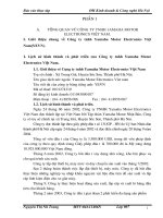
Start by mounting the components on the terminal strip as shown in Figure
1, carefully checking the position and value of each one. The three
capacitors are all the same, and so present no problem. They (and the
resistors) may be connected either way round, unlike the two semi-
conductors (see later). The resistors are coded by means of coloured bands.
You can refer to Chapter 7 if you have difficulty remembering the colours
and their values.
Figure 1 Terminal strip –
position of components
Radio and Electronics Cookbook
2
1. Brown, Black, Yellow 100 000 ohms (R1, R5, R6)
2. Green, Blue, Brown 560 ohms (R2)
3. Red, Violet, Brown 270 ohms (R3)
4. Brown, Black, Orange 10 000 ohms (R4)
The integrated circuit (the ZN414Z) and the transistor (the BC184) must be
connected correctly. Check Figure 1 carefully before fitting each device.
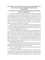
Now wind the coil. Most tubes are about 42 mm diameter and 110 mm
long. Don’t worry if your tube is slightly different; it shouldn’t matter. Make
two holes, about 3 mm apart, about 40 mm from one end, as shown in
Figure 2. Loop your enamelled wire into one hole and out of the other, and
draw about 100 mm through; loop this 100 mm through again, thus
anchoring the wire firmly. Now wind on 80 turns, keeping the wire tight
and the turns close together but not overlapping. After your 80th turn,
make another two holes and anchor the wire in the same way as before.
Again, leave about 100 mm free after anchoring. Using another piece of
enamelled wire (with 100 mm ends as before), loop one end through the
same two holes which contain the end anchor of the last winding, wind two
turns and anchor the end of this short winding using another pair of holes.
Figure 2 shows the layout.
Figure 2 The layout of the
parts on the wooden base
A medium-wave receiver
3
With some glass paper, remove the enamel from the ends of both pieces
of wire which go through the same holes (i.e. the bottom of the large coil
and the top of the small coil), then twist these bare ends together.
Remove the enamel from the remaining ends of the coil. The coil is now
finished!
The baseboard can be any piece of wood about 150 mm square. Fix the coil
near the back edge using drawing pins and connect the wires from the coils
to the terminal strip as shown in Figure 2. Using short pieces of PVC-
insulated wire (and with assistance if you have never soldered before),
solder one piece across the two outer tags of the variable capacitor, shown
by the dotted line in Figure 2, and then two longer pieces to the centre tag
and one outside tag. Connect these to the terminal strip. Then solder two
more insulated wires on to the jack socket (into which you will plug your
crystal earpiece), the other ends going to the terminal strip. The last two
wires (one must be red) need to be soldered on to the battery box, their
other ends going to the terminal strip also. Make sure the red wire goes to
the positive terminal on the battery, and is connected to terminal 9. The
other connection to the battery goes to terminal 10.
Attach the terminal strip to the baseboard with small screws or double-sided
sticky tape. The other parts can be mounted the same way.
Listening is done ideally with the recommended crystal earpiece. Don’t be
tempted to use your Walkman earpieces; they are not the same and will
not perform anything like as well. The receiver should work without an
extra aerial, but one can be attached to terminal 1 if necessary. A long
piece of wire mounted as high as possible is ideal. The Audio-frequency
Amplifier project will enable you to use a loudspeaker with your receiver,
using the signal from the jack socket. No circuit modifications will be
needed!
Parts list
Resistors: all 0.25 watt, 5% tolerance
R1, R5, R6 10 kilohms (k⍀)
R2 560 ohms
R3 270 ohms
R4 10 kilohms (k⍀)
Capacitors
C1, C2, C3 100 nanofarads (nF)
500 picofarads (pF)
Semiconductors
ZN414Z, BC184
Radio and Electronics Cookbook
4
Additional items
12-way 2 A terminal strip
22 metres of 28 SWG enamelled copper wire
A few short pieces of coloured PVC-insulated wire
Crystal earpiece
3.5 mm jack socket
1.5 V AA-size battery and box
Toilet roll tube
Double-sided sticky tape or selection of screws
Tools required
Small screwdriver, soldering iron.
2 An audio-frequency
amplifier
Introduction
This simple amplifier can be built by anyone who is able to solder
reasonably well. It doesn’t require any setting up and, provided our
instructions are followed exactly, will work very well. The circuit diagram is
included for the benefit of our more advanced readers, but it is not needed
in the construction process. Please practise your soldering before you start,
and don’t use a printed circuit board (PCB) until you are confident that your
soldering is up to scratch.
The amplifier can be used with other projects; it will provide plenty of
sound from the MW Radio or from the Morse Sounder projects. It will
usually be built into other pieces of equipment, so a box is not supplied
with the kit. There is no reason why it shouldn’t be put into a box and used
as a general-purpose amplifier to help test other projects.
The components
Before you start, you should check that you have all the components to
hand. A list and some helpful hints are given below.
An audio-frequency amplifier
5
1. PCB. The plain side is the component side and the soldered side is the
track side. Figure 1 shows the track side full size. Make the PCB from the
pattern given in Figure 1. Otherwise, build the circuit on a matrix
board.
2. Three resistors. Locate the gold or silver band around the resistor, and
turn the resistor until this band is to the right. There are three coloured
bands at the left-hand end of the resistor. Find the resistor whose colours
are YELLOW, VIOLET, RED, and look at the resistor colour code chart
which you will find in Chapter 7. From this, you will see that YELLOW
indicates the value 4, VIOLET the value 7, and RED the value 2. The
first two colours represent real numbers, and the last value is the number
of zeros (noughts) which go after the two numbers. So, the value is 47
with two zeros, i.e. 4700 ohms. In this way, the resistor coloured
BROWN, GREY, BROWN has a value of 180 ohms, and the last one,
BROWN, RED, GREEN, has a value of 1 200 000 ohms. The ohm (often
written as the Greek letter omega (⍀)) is the unit of resistance. If you do
not yet feel confident in identifying resistors by their colours, use the
Resistor Colour Codes given in Chapter 7.
3. Four capacitors. The two small ‘beads’ are tantalum capacitors and will be
marked 4.7 F or 47, with a ‘+’ above one lead. A tubular capacitor with
wires coming from each end should be marked 220 F, with one end
marked ‘+’ or ‘–’. This is called an axial capacitor because the wires lie on
the axis of the cylinder. This is in contrast to the final capacitor, where both
wires emerge from the same end. This is a radial capacitor, and will be
marked 47 F. Again, one lead will be marked ‘+’ or ‘–’. Capacitors
marked like this are said to be polarised, and it is vital that these are placed
on the PCB the right way round, so take notice of those signs!
4. Two diodes. These are tiny glass cylinders with a band around one end,
and may be marked 1N4148; this is their type number. Like polarised
capacitors, they must be put on the PCB the correct way round!
Figure 1 The toil pattern of
the PCB – looking from the
track side
Radio and Electronics Cookbook
6
5. Three transistors. One should be a BC548 (or a BC182), the other two
should be BC558 (or BC212).
6. One volume control with internal switch.
7. One loudspeaker. This is quite fragile – don’t let anything press against
the cone.
8. One PP3 battery clip with red and black leads.
Putting it together
Lay the PCB on a flat, clean surface with the track side downwards. It is
always useful to compare the layout with the circuit diagram, given here in
Figure 3. Although you can’t see it, the D-i-Y Radio sign should be at the
top. Compare the hole positions with those shown in Figure 2. Bend the
resistor wires at right angles to their bodies so that they fit cleanly into the
holes in the PCB. Push each resistor towards the board so that it lies flat on
the board. Then supporting each one, turn the board over and splay out the
wires just enough to prevent the resistor falling out. Then, solder each wire
to its pad on the PCB, and cut off the excess wire. When you have more
confidence, you can cut of the excess wire before soldering; it often makes
a tidier joint.
Figure 2 Positions of the
components on the printed
circuit board (PCB)
An audio-frequency amplifier
7
Now fit the four capacitors. Each must be connected the right way round,
so look at each component, match it up with the diagram of Figure 2, bend
its wires carefully and repeat the soldering process you performed with the
resistors, making sure that the components are close to the board and not up
on stilts! Fit the two diodes the correct way round, and solder then as
quickly as you can – they don’t like to be fried!
Mount the transistors about 5 mm above the PCB. Make sure the correct
transistors are in the correct places, and that the flats on the bodies match
up with those shown in Figure 2.
Mount the volume control so that the spindle comes out from the front of
the board. Use a piece of red insulated wire to the pad marked + on the PCB,
and a black piece to the pad marked –, and solder these to the tags on the
back of the control, as shown in Figure 4. Connect the two leads from the
battery clip to the other tags on the switch; Figure 4 will help you. Finally,
use two pieces of insulated wire about 100 mm long, twisted together, to
connect the loudspeaker to the PCB.
Figure 3 The amplifier’s
circuit diagram
Figure 4 Connections to
switch on back of VR1
Radio and Electronics Cookbook
8
Box clever!
If you wish to put the amplifier into a box, there is no problem; almost any
box that is big enough will do. All that is needed is one hole big enough to
accept the bush of the volume control; the PCB will be supported by the
volume control. The prototype was not fitted into a box, but mounted on an
odd piece of aluminium, bent into an L-shape and screwed on to a wooden
base. The loudspeaker was mounted on the aluminium panel by two small
pieces of aluminium with 3 mm holes drilled in them, which acted as clips
around the edge of the speaker. Drill a few holes in the panel in the position
of the speaker to let the sound get out!
Your input signal can be connected to the amplifier with two short pieces of
wire, but if the connection needs to be long, use screened cable, with the
braid connected as shown in Figure 2.
If you decide to use a different loudspeaker, make sure that its impedance
(the resistance value marked on the back of the magnet) is at least 35 ohms.
Anything lower may damage TR2 and TR3, and will certainly run down
your battery very quickly. You will be surprised at the uses you can find for
this little amplifier!
Parts list
Resistors: all 0.25 watt, 5% tolerance
R1 180 ohms (⍀)
R2 4.7 kilohms (k⍀)
R3 1.2 megohms (M⍀)
VR1 25 kilohms (k⍀) log with DPST switch
Capacitors: all rated at 25 V minimum
C1, C2 4.7 microfarads (F)
C3 47 microfarads (F)
C4 220 microfarads (F)
Semiconductors
TR1, TR3 BC548 npn
TR2 BC558 pnp
D1, D2 1N4148
Additional items
PCB
Speaker >35 ohms
PP3 battery clip and battery
A medium-wave receiver using a ferrite-rod aerial
9
3 A medium-wave receiver
using a ferrite-rod aerial
Introduction
This design came from the Norfolk Amateur Radio Club, and enables you to
build a simple Amplitude Modulation (AM) receiver for frequencies between
600 kHz and 1600 kHz. It should take you around 2 hours to build, and can
be used with Walkman-type earpieces. Figure 1 shows the circuit
diagram.
Description
The whole circuit is built on a 50 mm by 50 mm printed circuit board (PCB)
designed to fit on the inside of the lid of a plastic box, and is stuck there
using sticky pads, the shaft of the variable capacitor going through a hole in
Figure 1 Circuit and block
diagrams of the radio
Radio and Electronics Cookbook
10
the lid. Only two pairs of leads are soldered to the board – one pair goes to
the 1.5 V battery in its holder, and the other to the earphone socket. Figures
2a and 2b show the printed circuit and the component layout double size for
clarity. You are not obliged to build the circuit on a PCB.
Building it
1. Check and identify components. Tick the parts list.
2. Carefully unwind the wire. Use paper to make an insulating tube (called
a ‘former’) around the centre of the ferrite rod and secure it with
Sellotape. Now, close-wind all the wire (leave no gaps between adjacent
turns) around the paper former. Secure the winding with more
Sellotape, leaving 50 mm of wire free at each end for connection to the
circuit. See Figure 3a.
3. Solder in VC1.
4. Solder in the integrated circuit holder. There is a notch in one end of the
holder; this should face VC1. Solder also the wire link and the
capacitors. Be careful to avoid solder ‘bridges’ between adjacent tracks
on the PCB.
5. Solder the battery leads. These must be connected properly – the red
battery lead to the + (positive) area and the black lead to the –
(negative) area.
6. Strip bare 1 cm of insulation from the ends of two wires. Solder them
between the PCB and the headphone socket (see Figure 3b). Use the end
tabs on the socket. Using another pair of insulated wires connect the
ON/OFF switch to the PCB tabs shown in Figure 2b.
Figure 2a The PCB, solder side Figure 2b The PCB, component side
A medium-wave receiver using a ferrite-rod aerial
11
7. Fix the elastic band. This goes through the holes at the top of the PCB,
with the ferrite rod being slipped through the two end loops. (Note:
although the coating on the copper wire is designed to melt away
during soldering, it is quite common for difficulty to be experienced in
obtaining a good soldered joint; to be on the safe side, remove the
coating before soldering (with a small piece of sandpaper).) Carefully
place the wire ends of the coil through the PCB just above VC1, and
solder on the track side.
8. Fit IC1 into its holder. This should be done carefully, making sure that
all the pins are located above their respective clips before applying any
pressure! Make sure also that the notch on the IC (as shown in Figure
2b) matches the notch in the holder, and faces VC1.
9. Put battery in its holder. Listen for some noise in the headphones as
VC1 is rotated. Make sure the headphone plug is fully inserted into its
socket.
10. Fix the working board to the lid. Use the sticky pads and apply gentle
pressure. Fit the tuning knob, the ON/OFF switch and the earphone
socket.
11. Test again. If all is still working, fit the lid screws and admire your
completed radio!
Figure 3 Details of coil and
headphone socket
Radio and Electronics Cookbook
12
Parts list
Capacitors
C1, C2 0.01 microfarad (F)
C3, C4 0.1 microfarad (F)
VC1 500 picofarads (pF)
Semiconductor
IC1 ZN416E
Additional items
Plastic box (recommended size 76 × 64 × 50 mm internal)
8-pin DIL socket for IC1
Printed circuit board
Tuning knob for VC1
Wire link for PCB
2 m of 30 SWG copper wire, self-fluxing
Piece of paper 25 × 50 mm, to make the coil former
Ferrite rod 70 mm long by 10 mm diameter, approximately
Battery, AA size 1.5 V, with holder and attached wires
Miniature earphone socket (3.5 mm stereo jack)
ON/OFF switch (push-button SPST latched or slide switch)
4 off 100 mm insulated connecting wires, for jack socket and
ON/OFF switch
Pair Walkman-type earphones
Elastic band, to attach ferrite rod to PCB
4 off sticky pads for securing PCB to box lid
Kits
Ready-made PCBs may be available from Alan J. Wright, G0KRU,
Hewett School, Cecil Road, Norwich NR1 2PL.
4 A simple electronic organ
Introduction
This project has nothing to do with radio but, let’s admit it, any electronics
project is good experience! Why not build this little organ – it will keep the
children amused at least! It uses the popular NE555 integrated circuit,
which contains a circuit which will periodically switch the voltage on the
output pin between the supply voltage and zero. Just how frequently this
switching occurs depends upon the components external to the integrated
circuit. If this switching occurs several hundred or thousand times a second,
the change in voltage produced will generate a musical note when
connected to a small loudspeaker. The circuit is shown in Figure 1.
A simple electronic organ
13
Putting it together
(a) Using a PCB. The job is very simple. The placement of components on
the unsoldered side of the board is shown in Figure 2 and the design on
the copper track is illustrated in Figure 3. Put each component, in turn,
on the board, making sure that it lies flat on the board with its tags or
wires going cleanly through the holes provided for it; then, solder the
wires to the board, cropping them before or after the soldering,
Figure 1 Circuit diagram
Figure 2 Position of components on the printed circuit board (PCB)
Radio and Electronics Cookbook
14
depending on your preference. If you choose to use a holder for your
integrated circuit (highly recommended if your soldering is less than
perfect), make sure that the end with a notch in it faces R1 and R2, as
shown in Figure 2. Solder the two leads to the speaker to the tabs
marked S (either way round), having looped them through the two holes
to the right of the tabs in Figure 2. Looping them through the holes acts
as a strain relief, ensuring that the soldered joints are not subjected to
pulling and bending as you move the wires about. Do the same with the
battery leads, the red lead going to the + tab and the negative lead to the
– tab (which also has one speaker lead already attached to it). Figure 4
shows this in detail. Treat the loudspeaker with care – the cone is quite
fragile and must not be touched.
Figure 3 The connections
Figure 4 Battery plug and
loudspeaker connections