Cutting Tools Episode 2 Part 9 ppt
Bạn đang xem bản rút gọn của tài liệu. Xem và tải ngay bản đầy đủ của tài liệu tại đây (9.67 MB, 7 trang )
www.toolingandproduction.com
Chapter 18/Tooling & Production
1
2
Tooling & Production/Chapter 18
www.toolingandproduction.com
George Schneider, Jr. CMfgE
Professor Emeritus
Engineering Technology
Lawrence Technological University
Former Chairman
Detroit Chapter ONE
Society of Manufacturing Engineers
Former President
International Excutive Board
Society of Carbide & Tool Engineers
Lawrence Tech www.ltu.edu
Prentice Hall- www.prenhall.com
CHAPTER 18
Lapping and
Honing
Metal Removal
Cutting-Tool Materials
Metal Removal Methods
Machinability of Metals
Single Point Machining
Turning Tools and Operations
Turning Methods and Machines
Grooving and Threading
Shaping and Planing
Hole Making Processes
Drills and Drilling Operations
Drilling Methods and Machines
Boring Operations and Machines
Reaming and Tapping
Multi Point Machining
Milling Cutters and Operations
Milling Methods and Machines
Broaches and Broaching
Saws and Sawing
Abrasive Processes
Grinding Wheels and Operations
Grinding Methods and Machines
Lapping and Honing
Upcoming Chapters
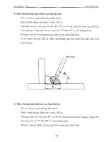
FIGURE 28.1: Typical lapping machine.
(Courtesy Engis Corp.)
18.1 Introduction
Lapping is a final abrasive finishing operation that produces extreme
dimensional accuracy, corrects minor imperfections of shape, refines
surface finish, and produces close fit between mating surfaces. Most
lapping is done with a tooling plate or wheel (the lap), and fine-grained
loose abrasive particles suspended in a viscous or liquid vehicle such as
soluble oil, mineral oil, or grease. A typical lapping operation is shown in
Figure 18.1.
Honing is a low velocity
abrading process. Material
removal is accomplished at
lower cutting speeds than in
grinding. Therefore, heat
and pressure are minimized,
resulting in excellent size
and geometry control. The
most common application of
honing is on internal cylin-
drical surfaces. The cutting
action is obtained using
abrasive sticks mounted on a
metal mandrel. Since the
work is fixed in such a way
as to allow floating, and no
clamping or chucking, there
is no distortion.
18.2 Lapping Processes
The principal use of the lapping
process is to obtain surfaces that are
truly flat and smooth. Lapping is also
used to finish round work, such as
precision plug gages, to tolerances of
0.0005 to 0.00002 inches.
Work that is to be lapped should be
previously finished close to the final
size. While rough lapping can remove
considerable metal, it is customary to
leave only 0.0005 to 0.005 inches of
stock to be removed.
Lapping, though it is an abrasive
process, differs from grinding or hon-
ing because it uses a ‘loose’ abrasive
instead of bonded abrasives like grind-
ing wheels (Fig. 18.2).
These abrasives are often purchased
‘ready mixed’ in a ‘vehicle’ often made
with an oil-soap or grease base. These
vehicles hold the abrasive in suspen-
sion before and during use. The paste
abrasives are generally used in hand-
lapping operations. For machine lap-
ping, light oil is mixed with dry abra-
sive so that it can be pumped onto the
lapping surface during the lapping op-
eration.
18.2.1 Lapping Machines
These machines are fairly simple
pieces of equipment consisting of a
rotating table, called a lapping plate,
and three or four conditioning rings.
Standard machines have lapping plates
www.toolingandproduction.com
Chapter 18/Tooling & Production
3
Chap. 18: Lapping and Honing
from 12 to 48 inches in diameter. Large
machines up to 144 inches are made. 1
to 20 HP motors run these tables. A
typical lapping machine is shown in
Figure 18.3.
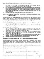
The lapping plate is most frequently
made of high-quality soft cast iron,
though some are made of copper or
other soft metals. This plate must be
kept perfectly flat. The work is held in
the conditioning rings. These rings ro-
tate as shown in Fig. 18.4. This rotation
performs two jobs. First it ‘conditions’
the plate, that is, it distributes the wear
so that the lapping plate stays flat for a
longer time. Secondly, it holds the
workpiece in place. The speed at which
the plate turns is determined by the job
being done. In doing very critical
parts, 10 to 15 RPM is used, and when
polishing, up to 150 RPM is used.
one step. Also, less time is required for
cleaning parts and processing waste;
throughput, along with overall produc-
tivity, is increased.
Lapping plates are manufactured
from various materials as described
below, and are available in standard
sizes from 6 to 48 inches in diameter.
Plates are supplied with square, spiral,
and concentric and radial grooves as
shown in Figure 18.5.
Iron - Aggressive Stock Removal:
• Excellent primary/roughing lap
plate, with long service life
• Often used as an alternative to
cast iron plates
• Produces a good surface finish on
most materials, especially metals and
ceramics.
Copper - Moderate to Aggressive
Stock Removal:
• Most widely used, universal com-
posite lap plate
• Excellent when primary and fin-
ishing lap are combined in a one step
operation
• Suitable for virtually any solid
material: metal, ceramic, glass, car-
bon, plastic, etc.
Ceramic - Moderate Stock Removal:
• Generally used to lap/polish ce-
ramic parts and other stain- sensitive
materials.
• Used in applications where metal-
lic-type contamination cannot be tol-
erated
• Affordable, more machinable al-
ternative to ‘natural’ ceramic plates.
Figure 18.3. Typical dual plate lapping ma-
chine. (Courtesy Engis Corporation)
Figure 18.2. Abrasive grit must be uniformly graded to be effective
in lapping.
Workpiece
Lap
A pressure of
about 3 pounds
per square inch
(PSI) must be ap-
plied to the
workpieces.
Sometimes their
own weight is suf-
ficient. If not, a
round, heavy pres-
sure plate is
placed in the con-
ditioning ring. The larger machines use
pneumatic or hydraulic lifts to place
and remove the pressure plates. Figure
18.5 shows various lapping plates.
The workpiece must be at least as
hard as the lapping plate, or the abra-
sive will be charged into the work. It
will take from 1 to 20 minutes to
complete the machining cycle. Time
depends on the amount of stock re-
moved, the abrasive used, and the qual-
ity required. Figure 18.6 shows a pro-
duction-lapping machine.
18.2.2 Grit and Plate Selection
Flatness, surface finish, and a pol-
ished surface are not necessarily
achieved at the same time or in equal
quality. For example, silicon carbide
compound will cut fast and give good
surface finish, but will always leave a
‘frosty’ or matte surface.
The grits used for lapping may occa-
sionally be as coarse as 100 to 280
mesh. More often the ‘flour’ sizes of
320 to 800 mesh are used. The grits,
mixed in slurry, are flowed onto the
plate to replace worn-out grits as the
machining process continues.
The case for using diamond super
abrasives rather
than conventional
abrasives such as
aluminum oxide
or silicon carbide
can be summed
up in three words.
Diamonds are
faster, cleaner,
and more cost-ef-
fective.
With diamond
slurries, the lap-
ping and polish-
ing phases of a
finishing opera-
tion can often be
combined into
Figure 18.4. Conditioning rings used in lapping operations.
4
Tooling & Production/Chapter 18
www.toolingandproduction.com
Chap. 18: Lapping and Honing
Tin/Lead - Fine Stock Removal:
• Most widely used finishing lap/
polishing plate
• Often used in place of polishing
pads
• Suitable for metal, ceramic and
other materials.
Tin - Fine Stock Removal
• Often used where lead-type con-
tamination cannot be tolerated
• Suitable for charging of extra-fine
particulates.
18.3 Advantages and Limitations
Any material, hard or soft, can be
lapped, as well as any shape, as long as
the surface is flat.
Advantages: There is no warping,
since the parts are not clamped and
very little heat is generated. No burrs
are created. In fact, the process re-
moves light burrs. Any size, diameter,
and thickness from a few thousandths
thick up to any height the machine will
handle can be lapped. Various sizes
and shapes of lapped parts are shown
in Figure 18.7.
Limitations: Lapping is still some-
what of an art. There are so many
variables that starting a new job re-
quires experience and skill. Even
though there are general recommenda-
tions and assistance from the manufac-
turers, and past experience is useful,
trial and error may still be needed to
get the optimum results.
18.4 Honing Processes
As stated earlier, honing is a low
velocity abrading process. Material re-
moval is accomplished at lower cutting
speeds than in grinding. Therefore,
heat and pressures are minimized, re-
sulting in excellent size and geometry
control. The most common application
of honing is on internal cylindrical
surfaces. A typical honing operation is
shown in Figure 18.8.
Machining a hole to within less than
0.001 inch in diameter and maintain-
ing true roundness and straightness
with finishes less than 20 u inches is
one of the more difficult jobs in manu-
facturing.
Finish boring or internal grinding
may do the job, but spindle deflection,
variation in hardness of the material,
and difficulties in precise work hold-
ing, make the work slow and the re-
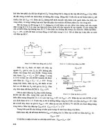
sults uncertain. Honing, because it
uses rectangular grinding stones in-
stead of circular grinding wheels, as
shown in Figures 18.9a and 18.9b, can
correct these irregularities.
Honing can consistently produce
finishes as fine as 4 u inches and even
finer finishes are possible. It can re-
move as little as 0.0001 inch of stock
or as much as 0.125 inch of stock.
However, usually only 0.002 to 0.020
inch stock is left on the diameter for
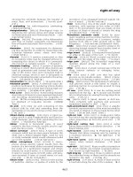
honing. As shown in Figure 18.10,
honing can correct a number of condi-
tions or irregularities, left by previous
operations.
18.5 Honing Machines
For most work, honing machines are
quite simple. The most used honing
machines are made for machining in-
ternal diameters from 0.060 to 6
inches. However, large honing ma-
chines are made for diameters up to 48
inches. Larger machines are some-
times made for special jobs.
The length of the hole that can be
honed may be anything from 1/2 inch
to 6 or 8 inches on smaller machines,
and up to 24 inches on larger ma-
chines. Special honing machines are
made which will handle hole lengths
up to 144
18.5.1 Horizontal Spindle Machines
Horizontal-spindle honing ma-
chines, for hand-held work with bores
up to 6 inches, are among the most
widely used. The machine rotates the
hone at from 100 to 250 FPM.
Figure 18.5. Typical lapping plates. (Cour-
tesy Engis Corporation)
Figure 18.7. Various sizes and shapes of lapped
parts. (Courtesy Engis Corporation)
Figure 18.8. Typical vertical honing operation.
(Courtesy Sunnen Products Co.)
Figure 18.6. Single plate lapping produc-
tion machine equipped for diamond abrasive
slurry use. (Courtesy Engis Corporation)
www.toolingandproduction.com
Chapter 18/Tooling & Production
5
Chap. 18: Lapping and Honing
The machine operator moves the
work back and forth (strokes it) over
the rotating hone. The operator must
‘float’ the work, that is, not press it
against the hone or the hole will be
slightly oval. Sometimes the work-
piece must be rotated.
Horizontal-spindle honing machines
are also made with ‘power stroking’. In
these, the work is held in a self-align-
ing fixture and the speed and length of
the stroke are regulated by controls on
the machine.
As a hone is being used, it is ex-
panded by hydraulic or mechanical
means until the desired hole diameter
is achieved. Various mechanical and
electrical devices can be attached to
the honing machine to control the rate
of expansion, and stop it when final
size is reached.
On the simplest hand-held ma-
chines, the operator may check the
bore size with an air gage, continue
honing, recheck, etc. until the size is
correct. A horizontal-spindle honing
machine is shown in Figure 18.11.
18.5.2 Vertical Spindle Machines
Vertical-spindle honing machines
are used especially for larger, heavier
work. These all have power stroking at
speeds from 20 to 120 FPM. The
length of the stroke is also machine
controlled by stops set up by the
operator.
Vertical honing machines are also
made with multiple spindles so that sev-
eral holes may be machined at once, as
in automobile cylinders (Figure 18.8).
Hone Body: The hone body is made
in several styles using a single stone
for small holes, and two to eight stones
as sizes get larger (Fig. 18.9b). The
stones come in a wide variety of sizes
and shapes. Frequently there are hard-
ened metal guides between the stones
to help start the hone cutting in a
straight line.
Cutting Fluid: A fluid must be used
with honing. This has several pur-
poses: to clean the small chips from
the stones and the workpiece, to cool
the work and the hone, and to lubricate
the cutting action.
A fine mesh filtering system must
be used, since recirculated metal can
spoil the finish.
A vertical honing operation was
shown in Figure 18.8. A few of the
parts honed on such a machine are
shown in Figure 18.12.
18.6 Abrasive Tool Selection
The abrasive honing stone must be
selected for the proper abrasive type,
bond hardness and grit size to deliver
the fastest stock removal and desired
surface finish. This selection is simple
if done in the following three steps:
Step One: Select the abrasive type
with respect to the material composi-
tion of the bore. There are four differ-
ent types of abrasives: aluminum ox-
ide, silicon carbide, diamond, and
CBN. All four of these were discussed
in the previous chapter. Each type has
its own individual characteristics that
make it best for honing certain materi-
als. Some simplified guidelines for
their use are:
• Mild steel hones best with alumi-
num oxide.
• Cast iron, brass, and aluminum
hone best with silicon carbide.
• Glass, ceramic, and carbide hone
best with diamond
• High speed tool steels, and super
alloys hone best with CBN.
Mandrel
Honing shoe
Honing stone
Workpiece
(a)
Figure 18.9a. Schematic illustration of the com-
ponents of an internal hone.
Figure 18.9b. Typical honing tool is shown be-
ing Checked (Courtesy: Gehring L.P.)
Alignment of tandem holes
Correcting bellmouth
Correcting taper
Correcting rainbow-shaped holes
Figure 18.10. Undesirable conditions that can
be corrected by honing.
6
Tooling & Production/Chapter 18
www.toolingandproduction.com
Chap. 18: Lapping and Honing
Diamond and CBN are considered
super abrasives because they are much
harder than conventional abrasives.
They cut easily and dull slowly, there-
fore allowing them to hone certain
materials much faster and more effi-
ciently than conventional abrasives.
However, as shown above, super abra-
sives are not suited to honing all mate-
rials. For instance, diamond does not
hone steel very well, and CBN may not
be as economical as using aluminum
oxide to hone soft steel.
Step Two: Use the stone hardness
suggested in the manufacturer’s cata-
log. If the stone does not cut, select the
next softer stone; if the stone wears too
fast, select the next harder stone. Stone
hardness does not refer to the hardness
of the abrasive grain, but to the
strength of the bonding material hold-
ing the abrasive grains together, as
discussed in the previous chapter. A
bond must be strong enough to hold
sharp abrasive grains in position to cut,
but weak enough to allow dulled grains
to be sloughed off to expose underly-
Figure 18.13. Plateau honed finish surface at 100x (Cour-
tesy: Gehring L.P.)
Figure 18.12. Parts honed on a vertical honing ma-
chine. (Courtesy Sunnen Products Co.)
Figure 18.11. Horizontal-spindle honing
machine (Courtesy Sunnen Products Co.)
ing sharp grains. If the bond is too
hard, the dulled abrasive grains will
not be allowed to fall off, and the stock
removal rate will be reduced. If the
bond is too soft, the stone will wear
excessively because sharp abrasive
grains fall off before they are fully
used.
Diamond and CBN abrasive grains
dull so slowly that standard ceramic or
resin bonds may not be strong enough
when honing rough out-of-round bores
in hard materials, or when CBN is used
to hone soft steel. Metal bonds are best
suited for these applications because
the grains are held in a sintered metal
matrix that is much stronger than stan-
dard bonds. As with choosing abrasive
type, stone bond hardness must be
matched to the application to maxi-
mize life and stock removal rates.
Step Three: Select the largest abra-
sive grit size that will still produce the
desired surface finish. Surface finish is
a function of the height of microscopic
peaks and valleys on the bore surface
and honing can produce al-
most any degree of rough-
ness or smoothness through
the use of different abrasive
grit sizes.
Honing oil can improve
stock removal rates by help-
ing the cutting action of the
abrasive grains. It prevents
pickup (spot welding of tool
to bore) and loading (chips
coating the stone). Honing
oil does this, not by acting as
a coolant, but through
chemical activity. The ingredients in
the oil produce this chemical activity.
Whenever the temperature rises at one
of the microscopic cutting points, the
sulfur in the oil combines with the iron
in the steel to form iron
sulfide, an unweldable
compound, and weld-
ing is prevented. The
antiwelding property of
honing oil also pre-
vents chips from stick-
ing together and coat-
ing the stone. Water
based coolants cannot
produce this type of
chemical activity. Use
of water-based coolants
will result in welding
of metallic guide shoes
to the part and loading of vitrified
abrasive honing stones.
18.7 Cylinder Block Honing
Bores sometime require a prelimi-
nary rough honing operation to remove
stock, followed by finish honing to get
the desired surface finish. A character-
istic feature of a honed surface finish
is crosshatch, which makes an excel-
lent oil retention and bearing surface.
The crosshatch pattern is generated in
the bore surface as the workpiece is
stroked back and forth over the rotat-
ing honing tool.
Plateau Honing: A few years ago a
special surface finish generated inter-
est in the engine rebuilding market.
With this finish, the valleys are deep
and the peaks have been removed to
form plateaus, giving the name plateau
honing or plateau finish as shown in
Figure 18.13. A recent test by a ring
manufacturer has shown that an engine
with a true plateau finish consumed
one-tenth the oil and had 80 percent
less cylinder bore wear than the en-
gines with conventional finishes.
Laser-Honing: With this process,
considerably better results are
achieved compared to traditional hon-
ing. Precisely defined surface struc-
tures can be obtained with Laser tech-
nology. Laser-honing is a combination
of honing and Laser processing. This
process generates Laser-produced lu-
bricant reservoirs into a specifically
defined area in order to achieve an
ideal plateau surface finish. Such a
hydrodynamic system can be produced
exactly where it is required as shown in
Figure 18.14.
Application of the Laser-honing
process requires three steps. In the first
step – rough honing – the macro-form
www.toolingandproduction.com
Chapter 18/Tooling & Production
7
Chap. 18: Lapping and Honing
Figure 18.15. Single-stroke honing tools use
expandable diamond-plated sleeves on a ta-
pered arbor. (Courtesy Sunnen Products Co.)
Figure 18.14. Laser generated honed finished surface (Cour-
tesy: Gehring L.P.)
of the bore is produced. In the second
step, precisely defined lubricant reser-
voirs are produced with the Laser. In
step three –finish honing – an ex-
tremely fine surface finish is obtained,
resulting in increased engine life by
reduction of wear in the cylinder sur-
face and on the piston rings.
18.8 Production Honing
Honing will not only remove stock
rapidly, but it can also bring the bore to
finish diameter within tight tolerances.
This is especially true if the honing
machine is equipped with automatic
size control. With every stroke, the
workpiece is pushed against a sensing
tip that has been adjusted to the finish
diameter of the bore. When the bore is
to size, the sensing tip enters the bore
and the machine stops honing. Size
repetition from bore to bore is .0001
inch to .0002 inch. The operator sim-
ply loads and unloads the fixture and
presses a button; everything else is
automatic.
Single-Stroke Honing: A still faster
and more accurate method of honing a
bore to final size is Single-Stroke hon-
ing. The Single-Stroke tool (Fig.
18.15) is an expandable diamond
plated sleeve on a tapered arbor. The
sleeve is expanded only during set up,
and no adjustments are necessary dur-
ing honing. Unlike conventional hon-
ing, where the work-
piece is stroked back
and forth over the tool,
in Single-Stroke hon-
ing the rotating tool is
pushed through the
bore one time, bring-
ing the bore to size.
The return stroke does
nothing to the bore ex-
cept get the workpiece
off the tool. Single-
Stroke honing is so ac-
curate and consistent,
that honed bores do
not require gaging.
Although Single-
Stroke honing has
many advantages, it is
limited in the types
and volumes of material that can be
removed. The size and overall volume
of chip produced in one pass must be
no more than the space between the
diamond grits, or the tool will seize in
the bore.
Workpieces are best suited for
Single-Stroke honing when they are
made of materials that produce small
chips, such as cast iron, and that have
interruptions that allow chips to be
washed from the tool as the bore is
being honed. Conventional honing
should be used whenever the material
to be honed produces long stringy
chips, or the amount of stock to be
removed is large.
18.9 Advantages and Limitations
Honing has developed into a produc-
tive manufacturing
Process, some advantages and limi-
tations will be discussed below:
Advantages: The workpiece need
not be rotated by power, there are no
chucks, faceplates, or rotating tables
needed, so there are no chucking or
locating errors. The hone is driven
from a central shaft, so bending of the
shaft cannot cause tapered holes as it
does when boring. The result is a truly
round hole, with no taper or high or
low spots, provided that the previous
operations left enough stock so that the
hone can clean up all the irregularities.
Honing uses a large contact area at
slow speed compared with grinding or
fine boring, which use a small contact
area at high speed. Because of the
combined rotating and reciprocating
motion used, a cross hatched pattern is
created which is excellent for holding
lubrication. Diameters with 0.001 to
0.0001 inch and closer accuracies can
be repeatedly obtained in production
work.
Honing can be done on most materi-
als from aluminum or brass to hard-
ened steel. Carbides, ceramics and
glass can be honed by using diamond
stones similar to diamond wheels.
Limitations: Honing is thought of
as a slow process. However, new ma-
chines and stones have shortened hon-
ing times considerably. Horizontal
honing may create oval holes unless
the work is rotated or supported. If the
workpiece is thin, even hand pressure
may cause a slightly oval hole.