Cutting Tools Episode 1 Part 2 ppt
Bạn đang xem bản rút gọn của tài liệu. Xem và tải ngay bản đầy đủ của tài liệu tại đây (667.3 KB, 18 trang )
Cutting
Tool
Applications
Cutting Tool Applications
By George Schneider, Jr. CMfgE
2
Tooling & Production/Chapter 2
www.toolingandproduction.com
2.1 Inroduction
The process of metal removal, a process in
which a wedge-shaped tool engages a
workpiece to remove a layer of material in
the form of a chip, goes back many years.
Even with all of the sophisticated equip-
ment and techniques used in today’s mod-
ern industry, the basic mechanics of form-
ing a chip remain the same. As the cutting
tool engages the workpiece, the material
directly ahead of the tool is sheared and
deformed under tremendous pressure. The
deformed material then seeks to relieve its
stressed condition by fracturing and flow-
ing into the space above the tool in the
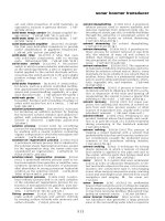
form of a chip. A turning tool holder gen-
erating a chip is shown in Figure 2.1.
2.2 Cutting Tool Forces
The deformation of a work material means
that enough force has been exerted by the
tool to permanently reshape or fracture the
work material. If a material is reshaped, it
is said to have exceeded its plastic limit. A
chip is a combination of reshaping and
fracturing. The deformed chip is separat-
ed from the parent material by fracture.
The cutting action and the chip formation
can be more easily analyzed if the edge of
the tool is set perpendicular to the relative
motion of the material, as shown in Figure
2.2. Here the undeformed chip thickness
t1 is the value of the depth of cut, while t2
is the thickness of the deformed chip after
leaving the workpiece. The major defor-
mation starts at the shear zone and diame-
ter determines the angle of shear.
A general discussion of the forces act-
ing in metal cutting is presented by using
the example of a typical turning operation.
When a solid bar is turned, there are three
Chip thickness
after cutting
(t
2
)
Rake
angle
(
α
)
Shear
angle (
φ
)
Undeformed
chip thickness
(t
1
)
Tool
FIGURE 2.1 A turning toolholder insert gener-
ating a chip. (Courtesy Kennametal Inc.)
FIGURE 2.2 Chip formation showing the defor-
mation of the material being machined.
Chapter 2
Metal Removal
Methods
Upcoming Chapters
Metal Removal
Cutting-Tool Materials
Metal Removal Methods
Machinability of Metals
Single Point Machining
Turning Tools and Operations
Turning Methods and Machines
Grooving and Threading
Shaping and Planing
Hole Making Processes
Drills and Drilling Operations
Drilling Methods and Machines
Boring Operations and Machines
Reaming and Tapping
Multi Point Machining
Milling Cutters and Operations
Milling Methods and Machines
Broaches and Broaching
Saws and Sawing
Abrasive Processes
Grinding Wheels and Operations
Grinding Methods and Machines
Lapping and Honing
George Schneider, Jr. CMfgE
Professor Emeritus
Engineering Technology
Lawrence Technological University
Former Chairman
Detroit Chapter ONE
Society of Manufacturing Engineers
Former President
International Excutive Board
Society of Carbide & Tool Engineers
Lawrence Tech.Univ.:
Prentice Hall:
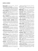
forces acting on the cutting tool (Fig.
2.3):
Tangential Force: This acts in a
direction tangential to the revolving
workpiece and represents the resistance
to the rotation of the workpiece. In a
normal operation, tangential force is the
highest of the three forces and accounts
for about 98 percent of the total power
required by the operation.
Longitudinal Force: Longitudinal
force acts in the direction parallel to the
axis of the work and represents the
resistance to the longitudinal feed of the
tool. Longitudinal force is usually
about 50 percent as great as tangential
force. Since feed velocity is usually
very low in relation to the velocity of
the rotating workpiece, longitudinal
force accounts for only about 1 percent
of total power required.
Radial Force: Radial force acts in a
radial direction from the center line of
the workpiece. The radial force is gen-
erally the smallest of the three, often
about 50 percent as large as longitudinal
force. Its effect on power requirements
is very small because velocity in the
radial direction is negligible.
2.3 Chip Formation and Tool Wear
Regardless of the tool being used or the
metal being cut, the chip forming
process occurs by a mechanism called
plastic deformation. This deformation
can be visualized as shearing. That is
when a metal is subjected to a load
exceeding its elastic limit. The crystals
of the metal elongate through an action
of slipping or shearing, which takes
place within the crystals and between
adjacent crystals. This action, shown in
Figure 2.4 is similar to the action that
takes place when a deck of cards is
Chap. 2: Metal Removal Methods
www.toolingandproduction.com
Chapter 2/Tooling & Production
3
given a push and sliding or
shearing occurs between the
individual cards.
Metals are composed of
many crystals and each crys-
tal in turn is composed of
atoms arranged into some
definite pattern. Without
getting into a complicated
discussion on the atomic
makeup and characteristics
of metals, it should be noted,
that the slipping of the crys-
tals takes place along a plane
of greatest ionic density.
Most practical cutting
operations, such as turning
and milling, involve two or
more cutting edges inclined
at various angles to the
direction of the cut.
However, the basic mecha-
nism of cutting can be
explained by analyzing cut-
ting done with a single cut-
ting edge.
Chip formation is sim-
plest when a continuous chip
is formed in orthogonal cut-
ting (Fig. 2.5a). Here the
cutting edge of the tool is
perpendicular to the line of
tool travel, tangential, longi-
tudinal, and radial forces are in the same
plane, and only a single, straight cutting
edge is active. In oblique cutting, ( Fig.
2.5b), a single, straight cutting edge is
inclined in the direction of tool travel.
This inclination causes changes in the
direction of chip flow up the face of the
tool. When the cutting edge is inclined,
the chip flows across the tool face with
a sideways movement that produces a
helical form of chip.
2.3.1 Chip Formation
Metal cutting chips have been classified
into three basic types:
• discontinuous or segmented
• continuous
• continuous with a built-up edge.
All three types of chips are shown in
Figure 2.6 a,b,and c.
Discontinuous Chip - Type 1:
Discontinuous or segmented chips are
produced when brittle metal such as cast
iron and hard bronze are cut or when
some ductile metals are cut under poor
cutting conditions. As the point of the
cutting tool contacts the metal, some
compression occurs, and the chip begins
FIGURE 2.3Typical turning operation
showing the forces acting on the cutting
tool.
FIGURE 2.6 Types of chip formations: (a) discontinuous, (b) continuous, (c) continuous
with built-up edge (BUE).
FIGURE 2.4 Chip formation compared to a sliding
deck of cards.
FIGURE 2.5 Chip formation showing both (a) orthogo-
nal cutting and (b) oblique cutting.
Tangential
force
Longitudinal
force
Radial force
101112131415 9 8 7
6
5
4
3
2
1
Tool
Workpiece
Workpiece
(a)
Workpiece
(b)
90¡
Tool Tool
Chip
Chip
Built-up
edge
Tool
(a) (b) (c)
Tool
Rough
workplace
surface
Chip
Primary
deformation
zone
Tool
Chap. 2: Metal Removal Methods
4
Tooling & Production/Chapter 2
www.toolingandproduction.com
flowing along the chip-tool interface.
As more stress is applied to brittle metal
by the cutting action, the metal com-
presses until it reaches a point where
rupture occurs and the chip separates
from the unmachined portion. This
cycle is repeated indefinitely during the
cutting operation, with the rupture of
each segment occurring on the shear
angle or plane. Generally, as a result of
these successive ruptures, a poor sur-
face is produced on the workpiece.
Continuous Chip - Type 2: The
Type 2 chip is a continuous ribbon pro-
duced when the flow of metal next to
the tool face is not greatly restricted by
a built-up edge or friction at the chip
tool interface. The continuous ribbon
chip is considered ideal for efficient cut-
ting action because it results in better
finishes.
Unlike the Type 1 chip, fractures or
ruptures do not occur here, because of
the ductile nature of the metal. The
crystal structure of the ductile metal is
elongated when it is compressed by the
action of the cutting tool and as the chip
separates from the metal. The process
of chip formation occurs in a single
plane, extending from the cutting tool to
the unmachined work surface. The area
where plastic deformation of the crystal
structure and shear occurs, is called the
shear zone. The angle on which the
chip separates from the metal is called
the shear angle, as shown in Figure 2.2.
Continuous Chip with a Built-up
Edge (BUE)- Type 3: The metal ahead
of the cutting tool is compressed and
forms a chip which begins to flow along
the chip-tool interface. As a result of
the high temperature, the high pressure,
and the high frictional resistance against
the flow of the chip along the chip-tool
interface, small particles of metal begin
adhering to the edge of the cutting tool
while the chip shears away. As the cut-
ting process continues, more particles
adhere to the cutting tool and a larger
build-up results, which affects the cut-
ting action. The built-up edge increases
in size and becomes more unstable.
Eventually a point is reached where
fragments are torn off. Portions of these
fragments which break off, stick to both
the chip and the workpiece. The build-
up and breakdown of the built-up edge
occur rapidly during a cutting action
and cover the machined surface with a
multitude of built-up fragments. These
fragments adhere to and score the
machined surface,
resulting in a poor
surface finish.
Shear Angle:
Certain characteris-
tics of continuous
chips are determined
by the shear angle.
The shear angle is
the plane where slip
occurs, to begin chip
formation (Figure
2.2). In Figure 2.7
the distortion of the
work material grains
in the chip, as com-
pared to the parent
material, is visible.
Each fracture line in
the chip as it moves upward
over the tool surface can be
seen, as well as the distorted
surface grains where the tool
has already passed. In certain
work materials, these distorted
surface grains account for work
hardening.
Regardless of the shear
angle, the compressive defor-
mation caused by the tool force
against the chip, will cause the
chip to be thicker and shorter
than the layer of workpiece
material removed. The work or
energy required to deform the
material usually accounts for
the largest portion of forces and
power involved in a metal
removing operation. For a
layer of work material of given
dimensions, the thicker the chip, the
greater the force required to produce it.
Heat in Metal Cutting: The mechan-
ical energy consumed in the cutting area
is converted into heat. The main sources
of heat are, the shear zone, the interface
between the tool and the chip where the
friction force generates heat, and the
lower portion of the tool tip which rubs
against the machined surface. The
interaction of these heat sources, com-
bined with the geometry of the cutting
area, results in a complex temperature
distribution, as shown in Figure 2.8.
The temperature generated in the
shear plane is a function of the shear
energy and the specific heat of the mate-
rial. Temperature increase on the tool
face depends on the friction conditions
at the interface. A low coefficient of
friction is, of course, desirable.
Temperature distribution will be a func-
tion of, among other factors, the thermal
conductivities of the workpiece and the
tool materials, the specific heat, cutting
speed, depth of cut, and the use of a cut-
ting fluid. As cutting speed increases,
there is little time for the heat to be dis-
sipated away from the cutting area and
so the proportion of the heat carried
away by the chip increases.
In Chapter 3 - Machinability of
Metals - this topic is discussed in more
detail.
2.3.2 Cutting Tool Wear
Cutting tool life is one of the most
important economic considerations in
metal cutting. In roughing operations,
the tool material, the various tool
angles, cutting speeds, and feed rates,
are usually chosen to give an economi-
Rake
angle
Tool
Relief
angle
Distorted
surface
grains
Parent material
Cut depth
Shear plane
Slip lines
Chip segment
Grain
fragments
Workpiece
Chip
Tool
675
750
850
930
930
1100
1100
1100…F
1300
1200
1200
1300
FIGURE 2.7 Distribution of work material during chip forma-
tion.
FIGURE 2.8 Typical temperature distribution in the
cutting zone.
Chap. 2: Metal Removal Methods
www.toolingandproduction.com
Chapter 2/Tooling & Production
5
cal tool life. Conditions giving a very
short tool life will not be economical
because tool-grinding, indexing, and
tool replacement costs will be high. On
the other hand, the use of very low
speeds and feeds to give long tool life
will not be economical because of the
low production rate. Clearly any tool or
work material improvements that
increase tool life without causing unac-
ceptable drops in production, will be
beneficial. In order to form a basis for
such improvements, efforts have been
made to understand the behavior of the
tool, how it physically wears, the wear
mechanisms, and forms of tool failure.
While the tool is engaged in the
cutting operation, wear may devel-
op in one or more areas on and near
the cutting edge:
Crater Wear: Typically, crater-
ing occurs on the top face of the
tool. It is essentially the erosion of
an area parallel to the cutting edge.
This erosion process takes place as
the chip being cut, rubs the top face
of the tool. Under very high-speed
cutting conditions and when
machining tough materials, crater
wear can be the factor which deter-
mines the life of the tool. Typical
crater wear patterns are shown in
Figures 2.9 and 2.10a. However, when
tools are used under economical condi-
tions, the edge wear and not the crater
wear is more commonly the controlling
factor in the life of the tool
Edge Wear: Edge wear occurs on
the clearance face of the tool and is
mainly caused by the rubbing of the
newly machined workpiece surface on
the contact area of the tool edge. This
type of wear occurs on all tools while
cutting any type of work material. Edge
wear begins along the lead cutting edge
and generally moves downward, away
from the cutting edge. Typical edge
wear patterns are shown in Figures 2.9
and 2.10b. The edge wear is also com-
monly known as the wearland.
Nose Wear: Usually observed after a
considerable cutting time, nose wear
appears when the tool has already
exhibited land and/or crater wear. Wear
on the nose of the cutting edge usually
affects the quality of the surface finish
on the workpiece.
Cutting tool material in general, and
carbide tools in particular, exhibit dif-
ferent types of wear and/or failure:
Plastic Deformation: Edge depres-
sion and body bulging appear, due to
excessive heat. The tool loses strength
and consequently flows plastically.
Mechanical Breakage: Excessive
force may cause immediate failure.
Alternatively, the mechanical failure
(chipping) may result from a fatigue-
type failure. Thermal shock also causes
mechanical failure.
Gradual Wear: The tool assumes a
form of stability wear due to interaction
between tool and work, resulting in
crater wear. Four basic wear mecha-
nisms affecting tool material have been
categorized as:
Abrasion: Because hard inclusions
in the workpiece microstructure plow
into the tool face and flank surfaces,
abrasion wear predominates at relative-
ly low cutting temperatures. The abra-
sion resistance of a tool material is pro-
portional to its hardness.
Adhesion: Caused by formation and
subsequent destruction of minute weld-
ed junctions, adhesion wear is common-
ly observed as built-up edge (BUE) on
the top face of the tool. This BUE may
eventually disengage from the tool,
causing a crater like wear. Adhesion
can also occur when minute particles of
the tool surface are instantaneously
welded to the chip surface at the tool-
chip interface and carried away with the
chip.
Diffusion: Because of high tempera-
tures and pressures in diffusion wear,
microtransfer on an atomic scale takes
place. The rate of diffusion increases
exponentially with increases in temper-
ature.
Oxidation: At elevated temperature,
the oxidation of the tool material can
cause high tool wear rates. The oxides
that are formed are easily carried away,
leading to increased wear.
The different wear mechanisms as
well as the different phenomena con-
tributing to the attritious wear of the
cutting tool, are dependent on the multi-
tude of cutting conditions and especial-
ly on the cutting speeds and cutting flu-
ids.
Aside from the sudden premature
breakage of the cutting edge (tool fail-
ure), there are several indicators of the
progression of physical wear. The
machine operator can observe these fac-
tors prior to total rupture of the edge.
FIGURE 2.9 Carbide insert wear patterns: (a) crater wear, (b) edge wear.
FIGURE 2.10 Carbide insert wear patterns: (a) crater wear, (b) edge wear. (Courtesy
Kennametal Inc.)
Nose
radius
R
Flank face
Depth-of-cut line
Edge wear
Rake face
Crater
wear
Depth-of-cut line
(a) (b)
(a) (b)
Chap. 2: Metal Removal Methods
6
Tooling & Production/Chapter 2
www.toolingandproduction.com
The indicators are:
• Increase in the flank wear size above a
predetermined value.
• Increase in the crater depth, width or
other parameter of the crater, in the rake
face.
• Increase in the power consumption, or
cutting forces required to perform the
cut.
• Failure to maintain the dimensional
quality of the machined part within a
specified tolerance limit.
• Significant increase in the surface
roughness of the machined part.
• Change in the chip formation due to
increased crater wear or excessive heat
generation.
2.4 Single Point Cutting Tools
The metal cutting tool separates chips
from the workpiece in order to cut the
part to the desired shape and size. There
is a great variety of metal cutting tools,
each of which is designed to perform a
particular job or a group of metal cut-
ting operations in an efficient manner.
For example, a twist drill is designed to
drill a hole of a particular size, while a
turning tool might be used to turn a vari-
ety of cylindrical shapes.
2.4.1 Cutting Tool Geometry
The shape and position of the tool, rela-
tive to the workpiece, have an important
effect on metal cutting. The most
important geometric elements, relative
to chip formation, are the location of the
cutting edge and the orientation of the
tool face with respect to the workpiece
and the direction of cut. Other shape
considerations are concerned primarily
with relief or clearance, i.e., taper
applied to tool surfaces to prevent rub-
bing or dragging against the work.
Terminology used to designate the
surfaces, angles and radii of single point
tools, is shown in Figure 2.11. The tool
shown here is a brazed-tip type, but the
same definitions apply to indexable
tools.
T & P TO PLACE FIG. 2.11 HERE
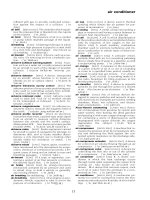
The Rake Angle: The basic tool
geometry is determined by the rake
angle of the tool as shown in Figure
2.12. The rake angle is always at the top
side of the tool. With the tool tip at the
center line of the workpiece, the rake
angle is determined by the angle of the
tool as it goes away from the workpiece
center line location. The neutral, posi-
tive, and negative rakes are seen in (a),
(b), and (c) in Figure 2.12. The angle
for these geometries is set by the posi-
tion of the insert pocket in the tool hold-
er. The positive/negative (d) and double
positive (e) rake angles are set by a
combination of the insert pocket in the
tool holder and the insert shape itself.
There are two rake angles: back rake
as shown in Figure 2.12, and side rake
as shown in Figure 2.13. In most turning
and boring operations, it is the side rake
that is the most influential. This is
because the side rake is in the direction
of the cut.
Rake angle has two major effects dur-
ing the metal cutting process. One
major effect of rake angle is its influ-
ence on tool strength. An insert with
negative rake will withstand far more
loading than an insert with positive
rake. The cutting force and heat are
absorbed by a greater mass of tool mate-
rial, and the compressive strength of
carbide is about two and one half times
greater than its transverse rupture
strength.
The other major effect of rake angle
is its influence on cutting pressure. An
insert with a positive rake angle reduces
cutting forces by allowing the chips to
flow more freely across the rake sur-
face.
Negative Rake: Negative rake tools
Side relief angle
Side rake
Side clearance angle
Nose radius
End-cutting edge angle
Side-cutting edge angle
Positive back rake
End relief
End clearance
Negative back rake
(a)
(b)
(c)
(d)
(e)
FIGURE 2.11 Terminology used to designate the surfaces, angles, and radii of single-
point tools.
FIGURE 2.12 With the cutting tool on center, various back rake angles are shown: (a)
neutral, (b) positive, (c) negative, (d) positive/negative, (e) double positive.
Chap. 2: Metal Removal Methods
www.toolingandproduction.com
Chapter 2/Tooling & Production
7
should be selected whenever workpiece
and machine tool stiffness and rigidity
allow. Negative rake, because of its
strength, offers greater advantage dur-
ing roughing, interrupted, scaly, and
hard-spot cuts. Negative rake also offers
more cutting edges for economy and
often eliminates the need for a chip
breaker. Negative rakes are recom-
mended on insert grades which do not
possess good toughness (low transverse
rupture strength)
Negative rake is not, however, with-
out some disadvantages. Negative rake
requires more horsepower and maxi-
mum machine rigidity. It is more diffi-
cult to achieve good surface finishes
with negative rake. Negative rake forces
the chip into the workpiece, generates
more heat into the tool and workpiece,
and is generally limited to boring on
larger diameters because of chip jam-
ming.
Positive Rake: Positive rake tools
should be selected only when negative
rake tools can’t get the job done. Some
areas of cutting where positive rake may
prove more effective are, when cutting
tough, alloyed materials that tend to
‘work-harden’, such as certain stainless
steels, when cutting soft or gummy met-
als, or when low rigidity of workpiece,
tooling, machine tool, or fixture allows
chatter to occur. The shearing action
and free cutting of positive rake tools
will often eliminate problems in these
areas.
One exception that should be noted
when experiencing chatter with a posi-
tive rake is, that at times the preload
effect of the higher cutting forces of a
negative rake tool will often dampen out
chatter in a marginal situation. This
may be especially true during lighter
cuts when tooling is extended or when
the machine tool has excessive back-
lash.
Neutral Rake: Neutral rake tools are
seldom used or encountered. When a
negative rake insert is used in a neutral
rake position, the end relief (between
tool and workpiece) is usually inade-
quate. On the other hand, when a posi-
tive insert is used at a neutral rake, the
tip of the insert is less supported, mak-
ing the insert extremely vulnerable to
breakage.
Positive/Negative Rake: The posi-
tive/negative rake is generally applied
using the same guidelines as a positive
rake. The major advantages of a posi-
tive/negative insert are that it can be
used in a negative holder, it offers
greater strength than a positive rake,
and it doubles the number of cutting
edges when using a two-sided insert.
The positive/negative insert has a ten
degree positive rake. It is mounted in
the normal five degree negative pocket
which gives it an effective five degree
positive rake when cutting. The posi-
tive/negative rake still maintains a cut-
ting attitude which keeps the carbide
under compression and offers more
mass for heat dissipation. The posi-
tive/negative insert also aids in chip
breaking on many occasions, as it tends
to curl the chip.
Double Positive Rake: The double
positive insert is the weakest of all
inserts. It is free cutting, and generally
used only when delicate, light cuts are
required which exert minimum force
against the workpiece, as in the case of
thin wall tubing, for example. Other
uses of double positive inserts are for
very soft or gummy work materials,
such as low carbon steel and for boring
small diameter holes when maximum
clearance is needed.
Side Rake Angles: In addition to the
back rake angles there are side rake
angles as shown in Figure 2.13. These
angles are normally determined by the
tool manufacturers. Each manufactur-
er’s tools may vary slightly, but usually
an insert from one manufacturer can be
used in the tool holder from another.
The same advantage of positive and
negative geometry that was discussed
for back rake, applies to side rake.
When back rake is positive so is side
rake and when back rake is negative so
is side rake.
Side and End Relief Angles: Relief
angles are for the purpose of helping to
eliminate tool breakage and to increase
tool life. The included angle under the
cutting edge must be made as large as
practical. If the relief angle is too large,
the cutting tool may chip or break. If
the angle is too small, the tool will rub
against the workpiece and generate
excessive heat, and this will in turn,
cause premature dulling of the cutting
tool.
Small relief angles are essential when
FIGURE 2.13 Side-rake-angle variations: (a) negative, (b) positive.
FIGURE 2.14 Lead-angle variations: (a) negative, (b) neutral, (c) positive.
Rotation
Feed
(a)
Rotation
Feed
(b)
Feed
Feed
Negative lead
angle
Positive lead
angle
Feed
Neutral lead
angle
(a) (b)
(c)
Chap. 2: Metal Removal Methods
8
Tooling & Production/Chapter 2
www.toolingandproduction.com
machining hard and strong materials,
and they should be increased for the
weaker and softer materials. A smaller
angle should be used for interrupted
cuts or heavy feeds, and a larger angle
for semi-finish and finish cuts.
Lead Angle: Lead angle (Fig. 2.14)
is determined by the tool holder which
must be chosen for each particular job.
The insert itself can be used in any
appropriate holder, for that particular
insert shape, regardless of lead angle.
Lead angle is an important considera-
tion when choosing a tool holder. A
positive lead angle is the most common-
ly used and should be the choice for the
majority of applications. Positive lead
angle performs two main functions:
• It thins the chip
• It protects the insert
The undeformed chip thickness
decreases when using a positive lead
angle.
Positive lead angles vary, but the
most common lead angles available on
standard holders are 10, 15, 30 and 45
degrees. As seen in Figure 2.15, the
volume of chip material is about the
same in each case but the positive lead
angle distributes the cutting force over a
greater area of the tool’s edge. This
allows a substantial increase in feed rate
without reducing the tool life because of
excessive loading. The greater the lead
angle, the more the feed rate can be
increased.
Positive lead angle also reduces the
longitudinal force (direction of feed) on
the workpiece. But positive lead angle
increases the radial force because the
cutting force is always approximately
perpendicular to the cutting edge (Fig.
2.16). This may become a problem
when machining a workpiece that is not
well supported. Care must be taken in
cases where an end support, such as a
tail stock center is not used.
A heavy positive
lead angle also has a
tendency to induce
chatter because of a
greater tool contact
area. This chatter is an
amplification of tool or
workpiece deflection
resulting from the
increased contact. In
this situation it is
appropriate to decrease
the positive lead angle.
A positive lead angle
protects the tool and promotes
longer tool life. As shown in
Figure 2.17 the tool comes in con-
tact with the workpiece well away
from the tool tip, which is the
weakest point of the tool. As the
tool progresses into the cut, the
load against the tool gradually
increases, rather than occurring as
a sudden shock to the cutting
edge. The positive lead angle
also reduces the wear on the cut-
ting edge caused by a layer of
hardened material or scale, by
thinning the layer and spreading it
over a greater area. These advan-
tages are extremely beneficial during
interrupted cuts. Another way that pos-
itive lead angle helps to extend tool life
is by allowing intense heat build-up to
dissipate more rapidly, since more of
the tool is in contact with the work-
piece.
Neutral and negative lead angle tools
also have some benefits. A neutral
angle offers the least amount of tool
contact, which will sometimes reduce
the tendency to chatter, and lowers lon-
gitudinal forces. This is important on
less stable workpieces or set-ups.
Negative lead angles permit machining
to a shoulder or a corner and are useful
for facing. Cutting forces tend to pull
the insert out of the seat, leading to
erratic size control. Therefore, negative
lead angles should be avoided if at all
possible.
2.4.2 Edge Preparation
Edge preparation is a step taken to pro-
long tool life or to enhance tool perfor-
mance. There are four basic approach-
es to edge preparation:
• Edge hone
• Edge “L” land
• Edge chamfer
• Combinations of the above
Many inserts, including carbide,
ceramic, etc., are purchased with a stan-
dard edge preparation, normally an edge
hone. The primary purpose of edge
preparation is to increase the insert’s
resistance to chipping, breaking, and
wear. Figure 2.18 illustrates the basic
edge preparations.
Tool materials such as carbide and
ceramic are very hard and brittle.
Therefore, a lead sharp cutting edge on
inserts made of these materials is
extremely prone to chipping and break-
ing. Once a cutting edge is chipped, the
wear rate is greatly accelerated or
breakage occurs. A prepared edge elim-
inates the sharp edge and provides other
benefits such as redistributing cutting
forces.
Edge Hone: The edge hone is by far
the most commonly used edge prepara-
tion. Many inserts are automatically
provided with an edge hone at the time
of purchase, especially larger inserts
that will be exposed to heavy cutting.
An edge hone on a ground or precision
insert must usually be specially request-
ed. A standard light hone in the United
States usually has a radius of 0.001 to
0.003 inch; A standard heavy hone has
a radius of 0.004 to 0.007 inch. Heavier
Feed (IPR)
Undeformed
chip thickness
Feed (IPR)
Undeformed
chip thickness
FIGURE 2.15 Lead angle vs. chip thick-
ness. A positive lead angle thins the chip
and protects the insert.
FIGURE 2.16 Lead angles and their effects on longitudinal
and radial cutting cutting-tool feed forces.
FIGURE 2.17 Gradual feed/workpiece contact
protects the cutting tool by slowing increasing the
load.
Radial
direction
Feed force
Feed
force
Longitudinal
direction
(a) (b)
Work piece
Feed
Initial contact
point
Chap. 2: Metal Removal Methods
www.toolingandproduction.com
Chapter 2/Tooling & Production
9
hones are available on request. The
heavier the hone, the more resistance an
edge has to chipping and breaking,
especially in heavy roughing cuts, inter-
rupted cuts, hard spot cuts, and scaly
cuts.
It is standard practice of all manufac-
turers to hone inserts that are to be coat-
ed before the inserts are subjected to the
coating process. The reason for this is
that during the coating process, the
coating material tends to build up on
sharp edges. Therefore it is necessary to
hone those edges to prevent build-up.
‘L’Land: The ‘L’land edge prepara-
tion adds strength to the cutting edge of
an insert. Essentially, the ‘L’ land
amplifies the advantages of negative
rake by diverting a greater amount of
cutting force into the body of the insert.
The ‘L’ land amplifies this condition
because the included angle at the
insert’s edges is 110 degrees as opposed
to 90 degrees. The ‘L’ land is particu-
larly beneficial when engaging severe
scale, interruptions, and roughing.
The ‘L’ land configuration is normal-
ly 20 degrees by two thirds of the fee-
drate. The feedrate should exceed the
land width by about one third. This is
not a hard and fast rule, but it does serve
as a good starting point. If the land
width is greater than the feedrate, severe
jamming of the chips, excessive high
pressures, and high heat will likely
occur, resulting in rapid tool failure.
Something other than a 20 degree
land angle may be considered, with
varying land width. Some experimenta-
tion may prove beneficial, however, if
the land angle is varied from 20 degrees
it should probably be less rather than
more than 20 degrees to keep from jam-
ming the chips.
An ‘L’ land is normally used only on
negative, flat top inserts placed at a neg-
ative rake angle. To use an ‘L’ land on
a positive or a positive/negative insert
would defeat the purpose of positive
cutting action.
Chamfer: A chamfer is a compro-
mise between a heavy hone and an ‘L’
land. A chamfer will also increase an
insert’s resistance to chipping and
breaking. In a shop situation a chamfer
is easier and quicker to apply than a
heavy hone, because it can be applied
with a grinder rather than a hand hone.
When a chamfer is applied it should be
very slight, 45 degrees by 0.005 to
0.030 inch.
Normally a chamfer presents a nega-
tive cutting situation which can result in
some problems. The area of application
for chamfers is limited and caution must
be exercised. A slight chamfer is often
used on a hard and brittle tool for mak-
ing a very light finishing cut on hard
work material. In this instance, the
chamfer will strengthen the cutting
edge.
Combinations: Any time that a sharp
edge can be eliminated the life of an
insert will likely be extended. When an
‘L’ land or chamfer is put on an insert, it
will make a dramatic improvement in
performance, but the ‘L’ land or cham-
fer will leave some semi-sharp corners.
To get the maximum benefit from an ‘L’
land or chamfer, it will help to add a
slight hone to each semi-sharp corner.
This will be of significant value in
extending tool life, particularly when a
large ‘L’ land is used.
Nose Radius: The nose radius of an
insert has a great influence in the metal
cutting process. The primary function
of the nose radius is to provide strength
to the tip of the tool. Most of the other
functions and the size of the nose radius
are just as important. The choice of
nose radius will affect the results of the
cutting operation; however, inserts are
provided with various standard radii
and, in most cases, one of these will
meet each specific cutting need.
The larger the radius, the
stronger the tool tip will be.
However, a large radius causes
more contact with the work surface
and can cause chatter. The cutting
forces will increase with a large
radius for the same reason,
increased contact with the work
surface. When taking a shallow
cut, a depth approximately equal to
the radius or less, the radius acts as
a positive lead angle, thinning the
chip. A large radius will allow the
cutting heat to dissipate more quickly
into the insert body, reducing the tem-
perature build-up at the cutting edge.
One of the most important influences
of a large radius is that of surface finish.
The larger the radius, the better the sur-
face finish will be at an equal feedrate.
A larger radius will allow a faster fee-
drate and yet obtain a satisfactory fin-
ish. During a finishing cut, the feedrate
should not exceed the radius if a reason-
able surface finish is required.
2.4.3 Chip Breakers
Breaking the chip effectively when
machining with carbide tools is of the
utmost importance, not only from the
production viewpoint, but also from the
safety viewpoint. When machining
steel at efficient carbide cutting speeds,
a continuous chip flows away from the
work at high speed.
If this chip is allowed to continue, it
may wrap around the toolpost, the
workpiece, the chuck, and perhaps
around the operator’s arm. Not only is
the operator in danger of receiving a
nasty laceration, but if the chip winds
around the workpiece and the machine,
he must spend considerable time in
removing it. A loss of production will
be encountered. Therefore it is impera-
tive that this chip be controlled and bro-
ken in some manner.
With the advent of numerial control
(NC) machining and automatic chip
handling systems, the control of chips is
becoming more important than ever.
The control of chips on any machine
tool, old or new, helps to avoid jam-ups
with tooling and reduces safety hazards
from flying chips. There is a great deal
of research and development being con-
ducted in chip control, much of which
has been very successful.
There are two basic types of chip
control being used with indexable insert
tooling: the mechanical chip breaker,
FIGURE 2.18 The three basic edge preparations are (a) edge hone, (b) L land, (c) edge cham-
fer.
X
X
Y
Y
(a) (b) (c)
R
Chap. 2: Metal Removal Methods
10
Tooling & Production/Chapter 2
www.toolingandproduction.com
Figure 2.19, and the sintered chip break-
er, Figure 2.20. Mechanical chip break-
ers are not as commonly used as sin-
tered chip breakers. There are more
parts involved with the mechanical chip
breaker, which increases the cost, and
the chip breaker hampers changing and
indexing the insert. However, mechan-
ical chip breakers are extremely effec-
tive in controlling chips during heavy
metal removing operations.
There are two groups of mechanical
chip breakers, solid and adjustable as
shown in Figure 2.21. Solid chip break-
ers are available in various lengths and
angles, to suit each metal cutting appli-
cation. The adjustable chip breaker can
eliminate the need for stocking various
sizes of solid chip breakers.
Sintered chip breakers are available
in many different configurations, some
designed for light feeds, some for heavy
feeds, and still others for handling both
light and heavy feeds. Figure 2.22
shows examples of the various sintered
chip breaker configurations available
from a single manufacturer. There are
single sided and double sided designs of
sintered chip breaker inserts.
Many of the designs will significant-
ly reduce cutting forces as well as con-
trol chips. Normally it would be more
economical to use a double sided insert
because of the addition-
al cutting edges avail-
able. However, this is
not always true. While
a double sided insert is
more economical under
moderate and finish cut-
ting conditions because
of its additional cutting
edges, a single sided
design will justify itself,
from a cost standpoint,
through more effective chip control and
reduced cutting forces in certain situa-
tions. Figure 2.23 shows five common
insert styles with sintered chip breakers.
Figure 2.22 illustrates that a single
sided insert is flat on the bottom as com-
FIGURE 2.19 Mechanical chip breaker.
FIGURE 2.21 Solid and adjustable chip breaker.
FIGURE 2.22 Various sintered chip
breaker configurations, with application
recommendations.
FIGURE 2.20 Sintered chip breaker.
Double-Sided General-Purpose Groove Geometries
Offers excellent mix of low cost per
cutting edge and effective chip control.
Designed for general-purpose use at low
feed rates.
Offers excellent mix of low cost per
cutting edge and effective chip control.
Designed for general-purpose use at
medium feed rates
Offers excellent mix of low cost per
cutting edge and effective chip control.
Designed for general-purpose use at high
feed rates
Single-Side Low Force Groove Geometries
Offers lower cutting forces than general-
purpose grooves in medium feed range
applications. Insert has 11¡ clearance
angle for use in positive rake tool holder.
Generates about 25% less cutting force
than general-purpose chip grooves. De-
signed for medium-feed applications
where force reduction, particularly in
the radial direction, is important.
Double-Sided Low Feed Groove Geometries
Offers excellent chip control at ultra-low
feed rates. Positive/negative design provides
some force reducing advantages. Low
cost per cutting edge.
Positive/negative design provides lower
cutting forces than general-purpose
grooves in low- to medium-feed range.
Offers low cost per cutting edge than
other force-reducing geometries.
Generates about 25% less cutting force
than general-purpose chip grooves. De-
signed for ultra-high-feed applications
where force reduction is important.
.004—
.020 ipr
feed
range
.005—
.065 ipr
feed
range
.012—
.070 ipr
feed
range
.005—
.045 ipr
feed
range
.006—
.050 ipr
feed
range
.012—
.078 ipr
feed
range
.003—
.024 ipr
feed
range
.004—
.032 ipr
feed
range
Chap. 2: Metal Removal Methods
www.toolingandproduction.com
Chapter 2/Tooling & Production
11
pared to a double sided insert. This flat
bottom provides a single sided insert
with better support under the cutting
edge in a severe cutting situation. The
single sided insert, because of its added
support, has the ability to remove larger
amounts of material with greater ease
and efficiency, making it more econom-
ical to use. Another reason the single
sided insert may be more economical is
that, under heavy machining conditions,
it is rare that all of the cutting edges of
a double sided insert can be used. The
intense thermal and mechanical shock
to the insert will normally damage it to
the point where the opposite cutting
edge is not usable and in a sense, wast-
ed. Figure 2.24 a,b shows two square
inserts with special purpose chip break-
ers.
Statistics have proven that under
severe conditions a single sided insert is
more often the most economical choice
because its higher efficiency will
remove more metal in less time.
Additionally, if half of the available
cutting edges of a double sided insert
are unusable, for reasons stated before,
then the more efficient single sided
insert, having essentially the same num-
ber of usable cutting edges, is the
most economical insert to use.
There are many other configura-
tions of chip breaker designs than
the ones shown in Figure 2.22.
Each manufacturer has its own.
The recommended application
areas are generally listed in each
manufacturer’s catalog. However,
for specific recommendations and
special applications, it is best to
consult the manufacturer.
Figure 2.25 shows the various
types of chips that are encountered
every day. Examining the chips
that are coming off a workpiece
will give a lot of information as to
how well the job is going, how tool
wear is progressing, and why premature
tool failure or short tool life is occur-
ring.
Straight Chips: Straight chips are
usually the most troublesome. They
string out all over the machine tool, they
get snarled in the tool, workpiece, and
fixturing, they cause tooling to break,
they jam up chip handling equipment,
they are difficult to remove, and they
are dangerous, especially when they
begin to whip around. Soft gummy low
carbon and tough steels usually cause
this type of chip. One of the quickest
ways to eliminate the straight chip, is to
increase the feedrate, because a thicker
chip breaks more easily. Other ways to
eliminate straight chips are to decrease
the lead angle, which would also thick-
en the chip, increase the speed, use a
negative rake tool, or use a chip breaker
insert.
Snarling Chips: Snarling chips are
continuous chips much the same as
straight chips. They are generally
caused by the same conditions as
straight chips and create the same prob-
lems. It stands to reason, therefore, that
to correct a snarling chip situation, the
same methods would be
used as with straight
chips. In addition, cool-
ing the chips with a
flood or mist coolant as
they come off the tool,
will frequently help to
break them.
Infinite Helix Chips:
Infinite helix chips are
chips that are near the
breaking point. The
problems this type of
chip creates are similar
to those created by straight chips.
Infinite helix chips are common when
machining very ductile material, such as
leaded or resulfurized steels, and other
soft materials. They will most often
occur when making light cuts with pos-
itive rake tools. Using a sintered chip
breaker insert, that will force the natur-
al chip flow direction to change, is often
effective in breaking the infinite helix
chip. An increase in feed or speed will
also help break the chip.
Full Turn Chips: Full turn chips are
not usually a problem so long as they
are consistent and without occasional
stringers. A consistent full turn chip is
near the ideal half turn chip.
Half Turn Chip: If there is such a
thing as a perfect chip, it is the half turn
or ‘6’shape chip. This is the chip shape
that the machinist strives for in his cut-
ting operation. The half turn chip is
known as the classic chip form. The
‘Half turn’ or just about perfect chip is
shown in Figure 2.26.
Tight Chips: Tight chips do not pre-
sent a problem from a handling or inter-
FIGURE 2.23 Five common insert shapes with
various sintered chip-breaker configurations.
(Courtesy American National Carbide Co.)
FIGURE 2.25 Various types of chip for-
mations.
FIGURE 2.24 Two square inserts with one-sided special-
purpose chip breakers. (Courtesy Iscar Metals, Inc.)
FIGURE 2.26 Half-turn chip or “perfect”
chip. (Courtesy Kennametal Inc.)
Straight chips
Snarling chips
Infinite helix chips
Full turns
Half turns
Tight chips
Chap. 2: Metal Removal Methods
12
Tooling & Production/Chapter 2
www.toolingandproduction.com
facing point of view, but these tight
chips are a sign that poor tool life or
premature tool failure may occur. The
tight chip is formed by very high pres-
sure and causes intense heat, deflection
of the tool and workpiece, and rapid
tool failure. A tight chip is a jammed
chip, meaning that its flow path is over-
ly restricted. Causes include; too high a
feed rate, too negative a rake angle,
improper chip breaker selection or set-
ting, or a worn insert.
Many times a straight, snarled or infi-
nite helix chip will be generated at the
start of a cutting operation, when the
insert is new. As the insert begins to
wear, the chip gradually becomes well
shaped and properly broken. It may
even progress into a tight chip and even-
tually cause catastrophic tool failure.
This is caused by a type of insert wear
known as cratering.( see Figures 2.9a
and 2.10a) In cratering, a groove is
worn into the insert causing a false chip
breaker groove to be formed. This is a
definite sign of a problem, such as the
insert is not of the correct carbide grade,
is not the correct geometry, or that the
cutting speed may be too fast.
2.5 Indexable Type Tooling
One of the more recent developments in
cutting tool design is the indexable
insert which is mechanically held in a
toolholder. Inserts are available in sev-
eral thicknesses and a variety of sizes
and shapes. The round, square, triangle,
and diamond account for the greatest
percentage. Many other shapes, includ-
ing the parallelogram, hexagon, and
pentagon, are used to meet specific
machining requirements. Each shape
has its advantages and limitations since
the operational, as well as the economi-
cal factors must be considered in tooling
selection. The most common insert
shapes were shown in Figure 2.23.
2.5.1 Indexable Insert Shapes
Indexable inserts have certainly estab-
lished their position and potential in the
metal working industry. The elimina-
tion of regrinding, accuracy of tool
geometry, reduced inventory tool costs,
and down time for tool changes, are
some of the advantages resulting from
the use of this tooling.
There are four basic shapes and a
variety of special shapes. Because
approximately 95 percent of all machin-
ing is done with the four basic shapes,
these are the ones of inter-
est here. The four basic
shapes are:
• square
• triangle
• diamond
• round
These shapes are avail-
able in many different con-
figurations for almost any
job. Each shape can be
obtained for positive, nega-
tive, or positive/negative
rake, with or without chip breaker
grooves, with or without holes, with
various edge preparations, in various
tolerances, and in various radii and
sizes. A variety of insert shapes and
configurations are shown in Figure 2.27
Choosing a particular shape or insert
requires a great deal of planning and
thought. The choice of insert shape
must be based on such factors as the
workpiece configuration and tolerance,
workpiece material, amount of material
to be removed, machine tool capability,
and economics.
The insert shape also has an influence
on insert strength. As shown in Figure
2.28, the greater the included angle at
the insert tip, the greater the strength.
The round insert and the 100 degree
corner of the first diamond shaped insert
are shown as the strongest. Because of
the higher cutting forces and the possi-
bility of chatter, these inserts are more
limited in use than the square shape.
Therefore, for practical purposes, the
square insert is the strongest for general
use. Triangle and diamond inserts
should only be used when a square can-
not be used, such as when machining to
a corner or a shoulder.
The Round Insert: Round or button
inserts give a good finish at heavy
feeds, and they are also ideal for form-
ing inside corner radii. Their shape pro-
vides the greatest geometric strength,
and they offer the maximum number of
indexes when light cuts are being taken.
The solid button type which is
held in place by means of a clamp,
generally has edges at 90 degrees
to the surfaces for use in negative
rake holders, thereby providing
cutting edges on both sides of the
insert. The CDH button type is
made in larger sizes and has a
counterbored hole. This button
has clearance and is normally held
in the toolholder with neutral
rake. A typical application is for tracing
or contouring, where the tool must gen-
erate forms which require a large por-
tion of the cutting edge to be in the cut.
Round inserts have their limitations,
however, since the large nose radius
thins the chips and increases the forces
between the tool and workpiece for a
given size cut. Very high radial forces
are usually incurred as compared with
normal cutting, particularly at normal
feed rates. Chatter and deflection often
result, especially when machining long-
chip materials. For this reason, button
inserts are applied with greater success
on cast iron and the other short-chip,
low-strength materials, although heavy
feed rates will often improve the cutting
action on ductile materials.
The Square Insert: Square inserts
provide four or eight cutting edges,
depending on the design of the tool-
holder. Positive rakes mean that relief
angles must be ground on the insert,
thereby eliminating the use of one side.
Square inserts are preferred for most
machining jobs, where the workpiece
and tool design relationships allow their
use. Their shape provides strength close
to that of the round insert, but with the
economy of four or eight cutting edges,
and also permits a reduction in the side
cutting edge angle and the problem
related to the chip-thinning action of the
round. Economical tool application dic-
tates the use of an insert shape which
gives the maximum number of cutting
FIGURE 2.27 Various insert shapes, with and without
holes, with and without chip breakers. (Courtesy
American National Carbide Co.)
FIGURE 2.28 Various insert shapes as related to
strength.
R
ound
3555608090100120
Strength increasing
Chap. 2: Metall Removal Methods
www.toolingandproduction.com
Chapter 2/Tooling & Production
13
edges and is compatible with the
machining operation. If the operation
requires machining to a square shoulder,
the square insert would be eliminated
because of the design of an ‘A’ style
tool. Since end cutting edge angle
(ECEA) is required so that the tool will
clear the machined surface, something
less than a 90 degree included angle
between the side and end of the tool is
mandatory.
The Triangular Insert: Owing to
design and application requirements,
one of which has just been pointed out,
the triangular insert has assumed an
important place in indexable tooling.
The triangle provides three or six cut-
ting edges, depending on whether relief
angles are required on the insert for use
in a positive rake holder. The 60 degree
included angle is not as strong as the 90
degree of the square, or the radius of the
button, yet many machining operations
are performed satisfactorily with trian-
gular inserts. Turning to a shoulder,
plunging and contouring, and numerous
other operations require a generous end
cutting edge angle which the triangle
can provide. The 60 degree included
angle is also suitable for threading oper-
ations.
Because of its fewer cutting edges
and lower strength, the triangular insert
and holder should only be used when
other geometric shapes will not meet the
job requirements.
The Pentagon Insert: A pentagon or
five-sided insert is a means of providing
one or two more cutting edges per
insert, and the extra edges are the main
reason for this design. There is, of
course, a strength advantage over the
square and triangle in the 108 degree
included angle. As in the case of the
square, the pentagonal shape sets up
certain design and application limita-
tions. The tool must always cut with a
side cutting edge angle (SCEA), which
thins the chip and improves tool life.
However, SCEA cannot always be used
owing to the requirements of the fin-
ished part’s shape or because the
increased radial forces cause chatter and
deflection of the workpiece. The mini-
mum SCE angle which can be used is
24 degrees. This then leaves 6 degrees
end cutting edge (ECE) angle. An
SCEA of 33 degrees results in 15
degrees of ECEA which is the same as
that used on standard ‘B’ style tools and
is quite adequate.
The Diamond Insert: The trend in
lathe design is toward machines which
generate the form on the workpiece.
This is accomplished by guiding the
tool so it faces, plunges, turns, and
forms radii, chamfers, and machines
other configurations. In order for a tool
to satisfy the requirements of these
complex maneuvers, it must meet cer-
tain design standards. Since the tool
often plunges along an angle, a great
amount of ECEA is needed. Back fac-
ing is also a common operation on such
setups, and this requires negative
SCEA.
The diamond insert was developed
specifically for tracing operations. The
industry’s standard marking system
includes designations for diamond
inserts with included angles of 86, 80
55, and 35 degrees. By far the most
popular size is the 55 degree included
angle diamond. This geometry appar-
ently meets the requirements of most
tracing operations. When the insert is
positioned in the toolholder and tool
block so that it cuts with 3 degree nega-
tive SCEA, it will back face with depths
of cut up to 0.020 inch and in most tool-
holders will be able to plunge at an
angle of 20 degrees with adequate clear-
ance.
Holding the insert securely in the
holder so that duplication of workpiece
size to tolerances specified is achieved,
has been a problem. The tendency for
the insert to twist in the pocket on turn-
ing and plunging operations, and to be
pulled out of the pocket on back facing
operations, has resulted in design
changes by some manufacturers.
Diamond tracer inserts are made in reg-
ular and elongated shapes. The elon-
gated diamond provides greater resis-
tance to the twisting action set up by the
cutting forces.
Further developments are still being
made in tracer inserts and holders so
that they will meet the exacting require-
ments of tracing operations better. In
some designs the diamond shaped
insert, either regular or elongated, is
locked into the pocket with an eccentric
pin. This gives a positive holding action
and locates the insert against the back
walls of the pocket, minimizing the
chances for movement during the con-
touring operations.
The selection of a tool for a tracing
operation should begin with an analysis
of the requirements of the contouring
operations. The tool selected should be
the one which provides the strongest
geometric shape and still meets the con-
touring requirements. Many tracing
jobs can be done satisfactorily with a
triangular insert. If no back facing is
included in the operations, no negative
SCEA is needed and a standard ‘A’ style
tool can be used. In some cases it is
possible to use a tool designed to cut
with SCEA. Generally, better tool life
will be realized with lower cost per cut-
ting edge, when tools without negative
SCEA can be used.
The Parallelogram Insert: The par-
allelogram-shaped insert provides some
advantages which make its use justified
in certain applications. When a long
side cutting edge is needed, it is some-
times more economical and advanta-
geous from a machining standpoint, to
use a parallelogram rather than a square
or triangle.
The parallelogram also permits the
construction of an ‘A’ style tool with
greater geometric strength than is possi-
ble with a triangular insert. A limitation
of the parallelogram design is the num-
ber of usable cutting edges. A negative
rake insert can be used on two corners
in a right or left-hand holder. To use the
remaining two cutting edges, the oppo-
site hand holder is required. Unless all
four corners can be used, the use of the
parallelogram insert may not be eco-
nomically justifiable.
The Hexagonal Insert: A versatile
tool makes use of a hexagonal shaped
insert. Turning, facing, and chamfering
can all be done from a number of posi-
tions. Its shape provides strong cutting
edges as in the case of the pentagon, but
also necessitates cutting with consider-
able SCEA. The number of usable cut-
ting edges in this design makes it a most
economical insert where it can be
applied.
The On-Edge Insert: The on-edge
insert concept (Fig. 2.29), has only been
in use for a short time, but is becoming
more common. The on-edge insert was
first developed for milling operations.
The main reason for its development
was to provide the strength needed to
withstand the constant interruption of
milling cuts. The on-edge concept is
now becoming more popular for turning
inserts as well.
The main use of the on-edge insert is
for rough cutting when cutting forces
are high and the interruptions are often
Chap. 2: Metal Removal Methods
14
Tooling & Production/Chapter 2
www.toolingandproduction.com
severe.
The extra thickness of the on-edge
insert offers more protection from heat
and shock damage to the opposite side
cutting edge during heavy roughing,
than is common with standard inserts.
A milling cutter section with on-edge
inserts is shown in Figure 2.30.
2.5.2 Indexable Inserts -
Classes and Sizes
Inserts are commercially available with
various degrees of dimensional toler-
ances, such as the inscribed circle of a
triangle, the measurement across the
flats of a square or elongated diamond,
thickness, nose radii, and tangency. All
these dimensions, and several other fac-
tors, contribute to the ability of an insert
to be accurately indexed and to machine
a given material to a specific size. The
need for inserts with different tolerances
depends not so much on the dimension-
al size of the finished part, but more on
how the insert is to be used in the
machining operation.
Unground Inserts: Through
improved manufacturing techniques,
many carbide producers can supply
inserts that are to the required specifica-
tions, thus elimi-
nating the grind-
ing operation.
Cutting edges
produced by this
method are not
only metallurgi-
cally sound in
structure, but are
also honed to
give them geo-
metric increase in
strength.
Utility
Inserts: This
type of insert is
ground on the top
and bottom faces
only.
Precision
Inserts: These are ground all over and
to close tolerances.
Honed Inserts: The development of
production honing techniques for
inserts has made standard inserts avail-
able to the machining industry in the
prehoned condition. These inserts have
the advantage of not only having the
cracked crystal layer removed from the
cutting edge area, but also from the cut-
ting tool surfaces. Lighter finishing
cuts taken with finishing grades of car-
bide should have small amounts of hon-
ing performed on the cutting edge.
Roughing grades should, conversely, be
honed heavily. Carbide Insert Honing
Equipment is shown in Figure 2.31.
Insert Size: The size of an insert is
determined by its inscribed circle (I.C.).
Every insert has an I.C. regardless of the
insert shape (Fig. 2.32). The I.C. is des-
ignated in fractions of an inch in the
United States, normally in 1/8 inch
increments. The thickness of the insert
is designated by its actual thickness in
increments of 1/16 inch, and the nose
radius is designated in increments of
1/64 inch.
The thickness of the insert is usually
standard to a particular I.C. Sometimes
however, a choice of thickness will be
available. In these situations, the thick-
ness that is appropriate to the amount of
cutting force that will be applied is the
optimum choice. If a thin insert is cho-
sen, a thicker shim should be used to
keep the cutting edge at the workpiece
centerline.
2.5.3 Indexable Insert
Identification System
A standard marking system, proposed
by the Cemented Carbide Producers
Association and approved by the
American National Standards Institute
(ANSI), has been adopted by the
cemented carbide manufacturers. A
new identification and numbering sys-
tem became necessary, due to the addi-
tion of an expanded range of types and
sizes of inserts incorporating a wide
variety of detail. Under this new sys-
tem, the insert number, with the manu-
facturer’s grade of carbide, is all that is
needed to describe the insert. (See Fig.
2.33). The eight sequences of marking
indexable inserts are:
• Shape • Size
• Thickness • Clearance
Angle
• Cutting Point • Class
• Other Conditions • Type
Insert Economics: The cost of car-
bide and other tool materials as well as
Cutting
force
Cutting
edge
Feed
FIGURE 2.29 On-edge turning tool
design.
FIGURE 2.32 The size of an insert is
determined by its inscribed circle (I.C.).
FIGURE 2.31 Carbide-insert honing equipment. (Courtesy
American National Carbide Co.)
FIGURE 2.30 On-edge milling cutter sec-
tion. (Courtesy Ingersoll Cutting Tool Co.)
I.C.
I.C.
I.C.I.C.
Chap. 2: Metal Removal Methods
www.toolingandproduction.com
Chapter 2/Tooling & Production
15
the cost of preparing these materials
into cutting tools is relatively high and
continuing to increase. Therefore, it is
most important to choose tool inserts
wisely. Here are some important things
to consider when making the choice:
• Chose a shape that offers the most cut-
ting edges.
Examples:
A negative insert has twice as many
cutting edges as a positive insert.
A square insert has 25 percent more
cutting edges than a triangle insert.
A double sided chip breaker insert has
twice as many cutting edges as a
single sided insert.
• Choose an I.C. appropriate to the
amount of material to be removed.
Examples:
A 1 inch I.C. square insert for a 1/4
inch depth of cut would be wasteful,
because a large piece of expensive
carbide would be used where a
smaller piece would achieve the
same result.
• Choose an insert tolerance that is
appropriate to the job being done. In
most cases an unground utility grade
will do the job. The closer the toler-
ance, the higher the cost. Tight insert
FIGURE 2.33 Standard Identification System for indexable inserts. (Courtesy Cemented Carbide Producers Association)
Insert Shape
Tolerance Class (1)
A —
B —
C —
D —
E —
H —
K —
L —
M —
O —
P —
R —
S —
T —
V —
W —
(B) Cutting Pt. (A) I.C. (T) Thickness
(2)A= 0.001
B = 0.0002
C = 0.0005
D = 0.0005
E = 0.001
G = 0.001
(3)M = 0.002-0.010
(3)U = 0.005-0.012
0.001
0.001
0.001
0.001
0.001
0.001
0.002-0.004
0.005-0.010
0.001
0.005
0.001
0.005
0.001
0.005
0.005
0.005
R = Blank with grind stock on all surfaces
S = Blank with grind stock on top and
bottom surfaces only
Tolerance given are plus and minus from nominal
These tolerances normally apply to indexable inserts
with facets (secondary cutting edges)
The tolerance depends on the size and shape of the insert
and should be as shown in the standards for the
corresponding shapes and sizes (See ANSI 894-25).
Cutting Point
Configuration
0 —
1 —
2 —
3 —
4 —
6 —
8 —
A —
D —
E —
F —
K —
L —
M —
N —
P —
Sharp Corner (.003 or less)
1/64 inch Radius
1/32 inch Radius
3/64 inch Radius
1/16 inch Radius
3/32 inch Radius
1/8 inch Radius
Square insert 45¡ Chamfer
Square insert 30¡ Chamfer
Square insert 15¡ Chamfer
Square insert 3¡ Chamfer
Square insert 30¡ Double
Chamfer
Square insert 15¡ Double
Chamfer
Square insert 3¡ Double
Chamfer
Truncated Triangle Insert
Flatted Corner Triangle
Clearance
N — 0¡
A — 3¡
B — 5¡
C — 7¡
P — 11¡
D — 15¡
E — 20¡
F — 25¡
G — 30¡
H — 0¡ — 11¡
J — 0¡ — 14¡
K — 0¡ — 17¡
L — 0¡ — 20¡
M — 11¡ — 14¡
R — 11¡ — 17¡
S — 11¡ — 20¡
Secondary facet angle may vary by — 12
Insert Style
A —
B —
C —
D —
E —
F —
G —
H —
J —
M —
P —
R —
Z —
X —
With hole
With hole and one countersink
With hole and two countersinks
Smaller than 1/4 I.C. with hole
Smaller than 1/4 I.C. without hole
Clamp-on type with chipbreaker-
no hole
With hole and chipbreaker top
and bottom
With hole, one countersink and
chipbreaker top only
With hole, two countersinks and
chipbreaker — top and bottom
With hole and
chipbreaker — top only
10¡ positive land with hole and
chipbreaker top and bottom
With hole and extra wide
chipbreaker top and bottom
High positive land with hole and
chipbreaker top and bottom
With hole, chipbreakers top and
bottom with negative land angle
Thickness
Regular Polygons and Dia-
monds Number 1/16ths
of an inch in thickness for IC
at 1/4 inch and over. For less
than 1/4 inch I.C. the number
of 1/32nds inch.
Rectangles and Parrallelo-
grams. Use width dimension
in place of I.C.
Cutting Edge
F — Sharp
E — Honed
T — K-Land
S — K-Land
w/Hone
Size I.C.
Regular Polygons and Dia-
monds Number 1/16ths
of an inch in I.C. when I.C. is
1/4 inch & over. For I.C. of
less than 1/4 inch the num-
ber of 1/32nd in I.C. Rectan-
gles & Parallelograms. Use 2
digits to size.
1st Digit - Number of inches
in width
2nd Digit - Number of inches
in length.
Parallelogram 85¡
Parallelogram 82¡
Diamond 80¡
Diamond 55¡
Diamond 75¡
Hexagon
Parallelogram 55¡
Rectangle
Diamond 86¡
Octagon
Pentagon
Round
Square
Triangle
Diamond 35¡
Trigon 80¡
TNMG — 432E
Chap. 2: Metal Removal Methods
16
Tooling & Production/Chapter 2
www.toolingandproduction.com
tolerances are normally required only
when the indexability of an insert is crit-
ical.
Example:
A ‘C’tolerance insert used for finishing
to a workpiece tolerance of plus or
minus 0.010 inch would not be neces-
sary. An ‘M’ or even a ‘U’tolerance
insert would be satisfactory.
• Choose a single sided insert when con-
ditions make its efficiency more eco-
nomical.
Example:
A heavy roughing cut has made the sec-
ond side of a less efficient double
sided insert unusable because of heat
and shock damage.
2.5.4 Mechanical Tool Holders
The revolution of the indexable insert
has resulted in the availability of a wide
range and variety of tool holders. A
number of tool holders with inserts are
shown in Figure 2.34.
To select or recommend the best
holder for every machining application
would be a formidable task. The prac-
tice in many manufacturing plants is to
standardize on one or two designs, so
that a minimum of repair parts and
accessories need to be carried in inven-
tory. There are basic designs and con-
struction elements common to all hold-
ers.
• The Shank
• The Seat
• The Clamp or Locking Device
Turning toolholders have been stan-
dardized as shown in Figure 2.35.
The Shank: The shank is the basic
element of the toolholder and its pur-
pose is to hold and present the cutting
edge to the workpiece. It usually has
drilled and tapped holes, slots and
cutouts, and it must provide a firm sup-
port for the carbide cutting edge.
Generally shanks are made of high-car-
bon or low-alloy steel, heat treated to
give physical properties that will resist
thread damage, chip erosion and defor-
mation under the tool-block clamping
FIGURE 2.34 Four toolholders with various insert styles and sizes (Courtesy
Kennametal Inc.)
1
Holding
Method
S — Screw only
M — Clamp and
Locking Pin
C — Clamp only
P — Locking Pin
Only
A — Straight Shank
with 0¡ side cutting
edge angle
B — Straight Shank
with 15¡ side
cutting edge angle
C — Straight Shank
with 0¡ end cutting
edge angle
D — Straight Shank
with 45¡ side cut-
ting angle
E — Straight Shank
with 30¡ side cut-
ting angle
F — Offset Shank
with 0¡ end cut-
ting edge angle
G — Offset Shank
with 0¡ side cut-
ting edge angle
H — Threading and
Shallow Grooving
I.D.
J — Offset Shank
with Negative 3¡
side cutting edge
angle
K — Offset Shank
with 15 end cut-
ting edge angle
L — Offset shank
with negative 5¡
side or end cutting
edge angle
M — Straight Shank
with 40¡ side cut-
ting edge angle
P — Straight Shank
with 27 1/2¡ side
cutting edge angle
R — Offset Shank
with 15¡ side cut-
ting edge angle
S — Offset Shank
with 45¡ side cut-
ting edge angle
T — Offset Shank
with 30¡ side cut-
ting edge angle
V — Threading and
shallow grooving
O.D.
W — Offset Shank
with 10¡ side cut-
ting edge angle
Z — Offset Threading
and grooving O.D.
4
Holder
Rake
N — Negative
O — Neutral
P — Positive
A — Hi-Positive
5
Hand
of Tool
L — Left
N — Neutral
R — Right
7 Insert
Size I.C.
Number of 1/8ths
on 1/4 IC and
over.
Number of 1/32nds
on 1/4 1 C and
under.
6
Toolholder
Shank Size
This position is a
significant number
which indicates the
holder cross sec-
tion. For square
shants this num-
ber represents the
number of six-
teenths of width
and height.
For rectangular
holders the first
digit represents the
number of eights of
width and the sec-
ond digit the num-
ber of quarters of
heights except the
following toolhold-
ers 11/4 x 11/2
which is given the
number 91.
2
Insert
Geometry
C — 80¡ Diamond
D — 55¡ Diamond
V — 35¡ Diamond
T — Triangle
S — Square
R — Round
*Q — Deep
Grooving
Cutoff and
Tracing
3 Toolholder Style
MTFNR — 16 — 4
FIGURE 2.35 Standard identification system for turning toolholders. (Courtesy Cemented Carbide Producers Association)
Chap. 2: Metal Removal Methods
www.toolingandproduction.com
Chapter 2/Tooling & Production
17
screws. Some designs and sizes which
do not make use of a carbide seat are
made of high alloy steel to resist defor-
mation under the insert.
The machined area for the seat and
insert is one of the most critical areas
and must be flat to provide the proper
support for the carbide seat and insert.
Common practice is to relieve the inside
corner for seat and insert clearance. The
intersections of the sides and bottom of
the pocket usually have a small radius,
since sharp corners may be the source of
cracks during heat treatment. A tool
shank with basic components is shown
in Figure 2.36.
The Seat: Most toolholders for
indexable inserts use a carbide seat or
pad as support for the insert. Cemented
tungsten carbide has a high compressive
strength, is hard, and can be ground to a
smooth flat surface. While hardened
steel has been used, and still is in some
designs, a strong preference for carbide
seats prevails.
The seats shown in Figure 2.37 are
typical and will serve to illustrate the
basic design. The periphery is cham-
fered at one face to clear any radius in
the steel shank pocket area. If the seat
or pad is held in place by a screw, the
hole will be deeply countersunk so that
the head of the screw will be well below
the surface. If the screw head projects
above the seat surface and the insert is
clamped down on it, breakage of the lat-
ter could result.
The seat is attached to the shank only
for convenience and to prevent its loss
when inserts are removed and replaced,
or if the holder is used vertically as in a
vertical turret lathe or upside down as in
the rear tool post of a turret lathe.
Seat flatness is one of the most criti-
cal requirements of tool holders.
Application tests have shown that an
out-of-flatness condition, of as little as
0.001 inch, can result in insert breakage.
Regardless of the design of the tool-
holder selected, the pocket and seat flat-
ness specifications should be carefully
examined and the highest standards
insisted upon.
The Clamp or Locking Device: Many
clamping and locking arrangements
have been developed for holding the
insert in a toolholder and there is proba-
bly no one best method or design, since
specific application requirements vary
so greatly. There are a number of fea-
tures and construction elements, howev-
er, which warrant consideration and
should influence the selection of a tool-
holder (Fig. 2.38).
The main function of the clamping
mechanism is to hold the insert securely
in position and many methods of doing
FIGURE 2.36 Tool shank with basic com-
ponents. (Courtesy Kennametal Inc.)
FIGURE 2.37 Schematic drawing of various insert-locking positions.
FIGURE 2.38 Various pin-type holder-locking options.
Chip breaker
Insert
Seat
Insert
Seat
Insert
Seat
Type 1
Retainer clip
Insert
Shim seat
Pin
Lock screw
Wedge
Shank
Type 2
Shim lock
Shim
Insert
Pin
Lock screw
Shank
Spring
(compressed)
Type 3
Shim lock
Shim
Insert
Lock screw
Lock
Holder body
Type 4
Holder
Lock pin
Insert
Shim
Lock cup
Chap. 2: Metal Removal Methods
18
Tooling & Production/Chapter 2
www.toolingandproduction.com
so are in use. On normal turning and
facing operations, the insert in most
styles of toolholders is held in the pock-
et by the cutting pressures,
and the load on the clamp is
very light except as affected
by the chip. Tracing and
threading operations
change the direction and
amount of the load applied
to the insert, and there is
more tendency to twist or
pull the insert out of the
pocket. The ability of the
clamping mechanism, to
perform satisfactorily under
such conditions, should be
carefully evaluated. The
use of a pin or lever mecha-
nism has been incorporated
in some designs to give a
more positive holding
action against the insert.
The suitability of the clamp design to
the machine toolholding blocks and to
the workpiece configuration should be
considered. Bulky club heads, high
clamps on clamping screws, or intricate
adjusting mechanisms may be in the
way, especially when tools must be
ganged up, or when machine and work-
piece clearances are small. A toolhold-
er which is not easily accessible and
must be removed from the machine so
the insert can be indexed or the chip
breaker adjusted, should not be consid-
ered suitable for the application. A
number of tool holders are shown in
Figure 2.39 where indexable inserts are
being held by both pins and clamps.
Tools which are positioned upside
down should have a wrench socket in
the lower end of the clamping screw so
that it can be easily reached. Chip-
breaker plates and clamp parts should
be secured so that they will not be
dropped in the chip pan when loosened
for insert changing.
FIGURE 2.39 Three toolholders in which inserts are
held by both pins and clamps. (Courtesy Sandvik
Coromant Corp.)