Process Selection - From Design to Manufacture Episode 2 Part 3 potx
Bạn đang xem bản rút gọn của tài liệu. Xem và tải ngay bản đầy đủ của tài liệu tại đây (562.97 KB, 20 trang )
//SYS21///INTEGRAS/B&H/PRS/FINALS_07-05-03/0750654376-CH002-1.3D – 204 – [35–248/214] 9.5.2003 2:05PM
Quality issues
.
High quality welds possible with little or no distortion.
.
No flux or filler used.
.
Integrity of vacuum important. Beam dispersion occurs due to electron collision with air molecules.
.
Out-of-vacuum systems must overcome atmospheric pressures at weld area.
.
Beams can be generated up to 700 mm from workpiece surface for high-vacuum systems; can be
reduced to less than 40 mm for out-of-vacuum.
.
Precise alignment of work required and held using jigs and fixtures.
.
Hazardous X-rays produced during processing which requires lead shielding.
.
Vacuum removes gases from weld area, e.g. hydrogen to minimize hydrogen embrittlement in
hardened steels.
.
Localized thermal stresses leads to a very small heat affected zone. Distortion of thin parts may occur.
.
Surface finish excellent.
.
Fabrication tolerances a function of the accuracy of the component parts and the assembly/jigging
method. Joints gaps less than 0.1 mm required. Therefore, abutment faces should be machined to
close tolerances.
204 Selecting candidate processes
//SYS21///INTEGRAS/B&H/PRS/FINALS_07-05-03/0750654376-CH002-1.3D – 205 – [35–248/214] 9.5.2003 2:05PM
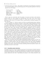
7.6 Laser Beam Welding (LBW)
Process description
.
Heat for fusion is generated by the absorption of a high power density narrow beam of light,
commonly known as a laser. Focusing of the laser is performed by mirrors or lenses (see 7.6F).
Materials
.
Dependent on thermal diffusivity and to a lesser extent the optical characteristics of material, rather
than chemical composition, electrical conductivity or hardness.
.
Stainless steel and carbon steels typically.
.
Aluminum alloys and alloy steels difficult to weld. Not used for cast iron.
Process variations
.
Many types of laser are available, used for different applications. Common laser types available are:
CO
2
, Nd:YAG, Nd:glass, ruby and excimer. Depending on economics of process, pulsed and
continuous wave modes are used.
.
Shielding gas such as argon sometimes employed to reduce oxidation.
.
Laser beam machines can also be used for cutting, surface hardening, machining (LBM) (see 5.4),
drilling, blanking, engraving and trimming, by varying the power density.
.
Laser beam spot and seam welding can also be performed on same equipment.
.
Laser soldering: provides very precise heat source for precision work.
Economic considerations
.
Weld rates ranging 0.25–13 m/min for thin sheet.
.
Production rates moderate.
.
High power consumption.
7.6F Laser beam welding process.
Laser Beam Welding (LBW) 205
//SYS21///INTEGRAS/B&H/PRS/FINALS_07-05-03/0750654376-CH002-1.3D – 206 – [35–248/214] 9.5.2003 2:05PM
.
Lead times can be short, typically weeks.
.
Setup times short.
.
Material utilization excellent.
.
High degree of automation possible.
.
Possible to perform many operations on same machine by varying process parameters.
.
Economical for low to moderate production runs.
.
Tooling costs very high.
.
Equipment costs high.
.
Direct labor costs medium. Some skilled labor required depending on degree of automation.
Typical applications
.
Structural sections
.
Transmission casings
.
Hermetic sealing (pressure vessels, pumps)
.
Transformer lamination stacks
.
Instrumentation devices
.
Electronics fabrication
.
Medical implants
Design aspects
.
Laser can be directed, shaped and focused by reflective optics permitting high spatial freedom in
2-dimensions. Horizontal welding position is the most suitable.
.
Typical joint designs using LBW: lap, butt and fillet (see Appendix B – Weld Joint Configura-
tions).
.
Mostly for horizontal welding.
.
Balance the welds around the fabrication’s neutral axis.
.
Path to joint area from the laser must be a straight line. Laser beam and joint must be aligned
precisely.
.
Intimate contact of joint faces required.
.
Filler rod rarely utilized, but for thick sheets or requiring multi-pass welds, a wire-feed filler attach-
ment can be used.
.
Minimal work holding fixtures required.
.
Minimum thickness ¼ 0.1 mm.
.
Maximum thickness ¼ 20 mm.
.
Multiple weld runs required on sheet thickness !13 mm.
.
Dissimilar thicknesses difficult.
Quality issues
.
Difficulty of material processing dictated by how close the material’s boiling and vaporization
points are.
.
Localized thermal stresses lead to a very small heat affected zone. Distortion of thin parts may
occur.
.
No cutting forces, so simple fixtures can be used.
.
Inert gas shielding, argon commonly, employed to reduce oxidation.
.
Control of the pulse duration important to minimize the heat affected zone, depth and size of molten
metal pool surrounding the weld area.
206 Selecting candidate processes
//SYS21///INTEGRAS/B&H/PRS/FINALS_07-05-03/0750654376-CH002-1.3D – 207 – [35–248/214] 9.5.2003 2:05PM
.
The reflectivity of the workpiece surface important. Dull and unpolished surfaces are preferred and
cleaning prior to welding is recommended.
.
Hole wall geometry can be irregular. Deep holes can cause beam divergence.
.
Surface finish good.
.
Fabrication tolerances a function of the accuracy of the component parts and the assembly/jigging
method.
Laser Beam Welding (LBW) 207
//SYS21///INTEGRAS/B&H/PRS/FINALS_07-05-03/0750654376-CH002-1.3D – 208 – [35–248/214] 9.5.2003 2:05PM
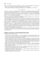
7.7 Plasma Arc Welding (PAW)
Process description
.
A plasma column is created by constricting an ionized gas through a water-cooled nozzle reaching
temperatures of around 20 000
C. The plasma column flows around a non-consumable tungsten
electrode, which provides the electrical current for the arc. The plasma provides the energy for
melting and fusion of the base materials and filler rod (when used) (see 7.7F).
Materials
.
Most electrically conductive materials.
.
Commonly and stainless steels, aluminum, copper and nickel alloys, refractory and precious metals.
.
Not cast iron, magnesium, lead or zinc alloys.
Process variations
.
Portable manual or automated a.c. or d.c. systems: d.c. system most common.
.
Two modes of operation used for welding:
.
Melt-in fusion for reduced distortion uses low currents
.
Key hole fusion at higher currents for full penetration on thick materials.
.
Choice of gas and their proportions important for two modes of operation:
.
Plasma gas: argon or argon–hydrogen mix
.
Shielding gas: argon or argon–hydrogen mix. Also helium or helium–argon mix used.
.
Plasma arc cutting: for cutting, slotting and profiling materials up to about 40 mm thickness using the
key-holing mode of operation.
7.7F Plasma arc welding process.
208 Selecting candidate processes
//SYS21///INTEGRAS/B&H/PRS/FINALS_07-05-03/0750654376-CH002-1.3D – 209 – [35–248/214] 9.5.2003 2:05PM
.
Plasma arc spraying: melting of solid feedstock (e.g. powder, wire or rod) and propelling the molten
material onto a substrate to alter its surface properties, such as wear resistance or oxidation
protection.
.
Filler rod sizes between 11.6 and 13.2 mm typically.
Economic considerations
.
Weld rates vary from 0.4 m/min for manual welding to 3 m/min for automated systems.
.
Alternative to TIG for high automation potential using key hole mode.
.
Welding circuit and system more complex than TIG. Additional controls needed for plasma arc and
filters and deionizers for cooling water mean more frequent maintenance and additional costs.
.
Economical for low production runs. Can be used for one-offs.
.
Tooling costs low to moderate.
.
Equipment costs generally high.
.
Direct labor costs moderate.
.
Finishing costs low.
Typical applications
.
Engine components
.
Sheet-metal fabrication
.
Domestic appliances
.
Instrumentation devices
.
Pipes
Design aspects
.
Design complexity high.
.
Typical joint designs possible using PAW: butt, lap, fillet and edge (see Appendix B – Weld Joint
Configurations).
.
Design joints using minimum amount of weld, i.e. intermittent runs and simple or straight contours
wherever possible.
.
Balance the welds around the fabrication’s neutral axis.
.
Distortion can be reduced by designing symmetry in parts to be welded along weld lines.
.
The fabrication sequence should be examined with respect to the above.
.
Design parts to give access to the joint area, for vision, filler rods, cleaning, etc.
.
Sufficient edge distances should be designed for. Avoid welds meeting at end of runs.
.
Mostly for horizontal welding, but can also perform vertical welding using higher shielding gas flow
rates.
.
Filler can be added to the leading edge of the weld pool using a rod, but not necessary for thin s ections.
.
Minimum sheet thickness ¼ 0.05 mm.
.
Maximum thickness, commonly:
.
Aluminum ¼ 3mm
.
Copper and refractory metals ¼ 6mm
.
Steels ¼ 10 mm
.
Titanium alloys ¼ 13 mm
.
Nickel ¼ 15 mm.
.
Multiple weld runs required on sheet thickness !10 mm.
.
Unequal thicknesses difficult.
Plasma Arc Welding (PAW) 209
//SYS21///INTEGRAS/B&H/PRS/FINALS_07-05-03/0750654376-CH002-1.3D – 210 – [35–248/214] 9.5.2003 2:05PM
Quality issues
.
High quality welds possible with little or no distortion.
.
Provides good penetration control and arc stability.
.
Access for weld inspection important, e.g. NDT.
.
Tungsten inclusions from electrode not present in welds, unlike TIG.
.
Joint edge and surface preparation important. Contaminates must be removed from the weld area to
avoid porosity and inclusions.
.
A heat affected zone always present. Some stress relieving may be required for restoration of
materials original physical properties.
.
Not recommended for site work in wind where the shielding gas may be gusted.
.
Need for jigs and fixtures to keep joints rigid during welding and subsequent cooling to reduce
distortion on large fabrications.
.
Care needed to keep filler rod within the shielding gas to prevent oxidation.
.
Tungsten inclusions can contaminate finished welds.
.
Nozzle used to increase the temperature gradient in the arc, concentrating the heat and making the
arc less sensitive to arc length changes in manual welding.
.
Plasma arc very delicate and orifice alignment with tungsten electrode crucial for correct
operation.
.
Important process variables for consistency in manual welding: welding speed, plasma gas flow
rate, current and torch angle.
.
‘Weldability’ of the material important and combines many of the basic properties that govern the
ease with which a material can be welded and the quality of the finished weld, i.e. porosity and
cracking. Material composition (alloying elements, grain structure and impurities) and physical
properties (thermal conductivity, specific heat and thermal expansion) are some important attributes
which determine weldability.
.
Surface finish of weld excellent.
.
Fabrication tolerances a function of the accuracy of the component parts and the assembly/jigging
method, but typically Æ 0.25 mm.
210 Selecting candidate processes
//SYS21///INTEGRAS/B&H/PRS/FINALS_07-05-03/0750654376-CH002-1.3D – 211 – [35–248/214] 9.5.2003 2:05PM
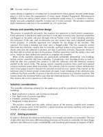
7.8 Resistance welding
Process description
.
Covers a range of welding processes that use the resistance to electrical current between two
materials to generate sufficient heat for fusion. A number of processes use a timed or continuous
passage of electric current at the contacting surfaces of the two parts to be joined to generate heat
locally, fusing them together and creating the weld with the addition of pressure, provided by current
supplying electrodes or platens (see 7.8F).
Materials
.
Low carbon steels commonly, however, almost any material combination can be welded using
conventional resistance welding techniques. Not recommended for cast iron, low melting point
metals and high carbon steels.
.
Electroslag Welding (ESW) is used to weld carbon and low alloy steels typically. Nickel, copper and
stainless steel less common.
7.8F Resistance welding process.
Resistance welding 211
//SYS21///INTEGRAS/B&H/PRS/FINALS_07-05-03/0750654376-CH002-1.3D – 212 – [35–248/214] 9.5.2003 2:05PM
Process variations
.
Resistance Spot Welding (RSW): uses two water-cooled copper alloy electrodes of various shapes
to form a joint on lapped sheet-metal. Can be manual portable (gun), single or multi-spot semi-
automatic, automatic floor standing (rocker arm or press) or robot mounted as an end effector.
.
Resistance Seam Welding (RSEW): uses two driven copper alloy wheels. Current is supplied in
rapid pulses creating a series of overlapping spot welds which is pressure tight. Usually floor
standing equipment, either circular, longitudinal or universal types.
.
Resistance Projection Welding (RPW): a component and sheet-metal are clamped between current
carrying platens. Localized welding takes place at the projections on the component(s) at the
contact area. Usually floor standing equipment, either single or multi-projection press type.
.
Upset resistance welding: electrical resistance between two abutting surfaces and additional pres-
sure used to create butt welds on small pipe assemblies, rings and strips.
.
Percussion resistance welding: rapid discharge of electrical current and then percussion pressure
for welding rods or tubes to sheet-metal.
.
Flash Welding (FW): parts are accurately aligned at their ends and clamped by the electrodes. The
current is applied and the ends brought together removing the high spots at the contact area
deoxidizing the joint (known as flashing). Second part is the application of pressure effectively
forging the weld.
.
ESW: the joint is effectively ‘cast’ between joint edges between a gap of about 20 to 50 mm. An
electric arc is used initially to heat a flux within water-cooled copper molding shoes spanning the
joint area. Resistance between the consumable electrode and the base material is then used to
generate the heat for fusion. The weld pool is shielded by the molten flux as welding progresses up
the joint.
.
A variant of ESW is Electrogas Welding (EGW). However, the process doesn’t use electrical
resistance as a heat source, but a gas shielded arc, therefore the molten flux pool above the weld
is not necessary. Used for thick sections of carbon steel.
Economic considerations
.
Full automation and integration with component assembly relatively easy.
.
High production rates possible due to short weld times, e.g. RSW ¼ 20 spots/min, RSEW ¼ 30 m/min,
FW ¼ 3 s/10 mm
2
area.
.
Automation readily achievable using all processes.
.
No filler metals or fluxes required (except ESW).
.
Little or no post-welding heat treatment required.
.
Minimal joint preparation needed.
.
Economical for low production runs. Can be used for one-offs.
.
Tooling costs low to moderate.
.
Equipment costs low to moderate.
.
Direct labor costs low. Skilled operators are not required.
.
Finishing costs very low. Cleaning of welds is not necessary typically, except with Flash Welding
(FW), which requires machining or grinding to remove excess material.
.
High deposition rates for ESW, but can still be slow.
Typical applications
.
RSW: car bodies, aircraft structures, light structural fabrications and domestic appliances
.
RSEW: fuel tanks, cans and radiators
212 Selecting candidate processes
//SYS21///INTEGRAS/B&H/PRS/FINALS_07-05-03/0750654376-CH002-1.3D – 213 – [35–248/214] 9.5.2003 2:05PM
.
RPW: reinforcing rings, captive nuts, pins and studs to sheet-metal, wire mesh
.
FW: for joining parts of uniform cross section, such as bar, rods and tubes, and occasionally sheet-
metal
.
ESW: joining structural sections of buildings and bridges such as columns, machine frames and
on-site fabrication
Design aspects
.
Typical joint designs: lap (RSW and RSEW), edge (RSEW), butt (FW and ESW), attachments (PW).
.
Access to joint area important.
.
Can be used for joints inaccessible by other methods or where welded components are closely
situated.
.
Spot weld should have a diameter between four and eight times the material thickness.
.
Can process some coated sheet-metals (except ESW).
.
Same end cross sections are required for FW.
.
For RSW, RSEW and PW:
.
Minimum sheet thickness ¼ 0.3 mm
.
Maximum sheet thickness, commonly ¼ 6mm
.
Mild steel sheet up to 20 mm thick has been spot- and seam-welded, but requires high currents
and expensive equipment.
.
For FW, sizes ranging 0.2 mm thick sheet to sections up to 0.1 m
2
in area.
.
Unequal thicknesses possible with RSW and RSEW (up to 3:1 thickness ratio).
.
ESW applied to sheet thicknesses of same order from 25 up to 500 mm using several guide tubes
and electrodes in one pass, but down to 75 mm for a single set. Vertical welds can restrict design
freedom in ESW.
Quality issues
.
Clean, high quality welds with very low distortion can be produced. Although a heat affected zone
always created, can be small.
.
Coarse grain structures may be created in ESW due to high heat input and slow cooling.
.
Surface preparation important to remove any contaminates from the weld area such as oxide layers,
paint and thick films of grease and oil. Resistance welding of aluminum requires special surface
preparation.
.
Welding variables for spot, seam and projection welding should be pre-set and controlled during
production, these include: current, timing and pressure (where necessary).
.
Electrodes or platens must efficiently transfer pressure to the weld, conduct and concentrate the
current and remove heat away from the weld area, therefore, maintenance should be performed at
regular intervals.
.
Spot, seam and projection welds can act as corrosion traps.
.
RSW, RSEW and PW welds can be difficult to inspect. Destructive testing should be intermittently
performed to monitor weld quality.
.
Depression left behind in RSW and RSEW serves to prevent cavities or cracks due to contraction of
the cooling metal.
.
Possibility of galvanic corrosion when resistance welding some dissimilar metals.
.
High strength welds are produced by FW. Always leaves a ridge at the joint area which must be
removed.
Resistance welding 213
//SYS21///INTEGRAS/B&H/PRS/FINALS_07-05-03/0750654376-CH002-1.3D – 214 – [35–248/214] 9.5.2003 2:05PM
.
‘Weldability’ of the material important and combines many of the basic properties that govern the
ease with which a material can be welded and the quality of the finished weld, i.e. porosity and
cracking. Material composition (alloying elements, grain structure and impurities) and physical
properties (thermal conductivity, specific heat and thermal expansion) are some important attributes
which determine weldability.
.
Surface finish of the welds fair to good for RSW, RSEW, FW and PW. Excellent for ESW.
.
No weld spatter and no arc flash (except ESW initially).
.
Alignment of parts to give good contact at the joint area important for consistent weld quality.
.
Repeatability typically Æ 0.5–Æ1 mm for robot RSW.
.
Axes alignment total tolerance for FW between 0.1 and 0.25 mm.
214 Selecting candidate processes
//SYS21///INTEGRAS/B&H/PRS/FINALS_07-05-03/0750654376-CH002-1.3D – 215 – [35–248/214] 9.5.2003 2:05PM
7.9 Solid state welding
Process description
.
A range of methods utilizing heat, pressure and/or high energy to plastically deform the material at
the joint area in order to create a solid phase mechanical bond (see 7.9F).
Materials
.
Cold Welding (CW): Ductile metals such as carbon steels, aluminum, copper and precious metals.
.
Friction Welding (FRW): can weld many material types and dissimilar metals effectively, including
aluminum to steel. Also thermoplastics and refractory metals.
7.9F Solid state welding process.
Solid state welding 215
//SYS21///INTEGRAS/B&H/PRS/FINALS_07-05-03/0750654376-CH002-1.3D – 216 – [35–248/214] 9.5.2003 2:05PM
.
Ultrasonic Welding (USW): can be used for most ductile metals, such as aluminum and copper
alloys, carbon steels and precious metals, and some thermoplastics. Can bond dissimilar materials
readily.
.
Explosive Welding (EXW): carbon steels, aluminum, copper and titanium alloys. Welds dissimilar
metals effectively.
.
Diffusion bonding (DFW): stainless steel, aluminum, low alloy steels, titanium and precious metals.
Occasionally copper and magnesium alloys are bonded.
Process variations
.
CW: process is performed at room temperature using high forces to create substantial deformation
(up to 95 per cent) in the parts to be joined. Surfaces require degreasing and scratch-brushing for
good bonding characteristics.
.
Cold pressure spot welding: for sheet-metal fabrication using suitably shaped indenting tools.
.
Forge welding: the material is heated in a forge or oxyacetylene ring burners. Hand tools and anvil
used to hammer together the hot material to form a solid state weld. Commonly associated with the
blacksmith’s trade and used for decorative and architectural work.
.
Thermocompression bonding: performed at low temperatures and pressures for bonding wires to
electrical circuit boards.
.
USW: hardened probe introduces a small static pressure and oscillating vibrations at the joint face
disrupting surface oxides and raising the temperature through friction and pressure to create a bond.
Can also perform spot welding using similar equipment.
.
Ultrasonic Seam Welding (USEW): ultrasonic vibrations imparted through a roller traversing the joint
line.
.
Ultrasonic soldering: uses an ultrasonic probe to provide localized heating through high frequency
oscillations. Eliminates the need for a flux, but requires pre-tinning of surfaces.
.
Ultrasonic insertion: for introducing metal inserts into plastic parts for subsequent fastening operations.
.
Ultrasonic staking: for light assembly work in plastics.
.
FRW: the two parts to be welded, one stationary and one rotating at high speed (up to 3000 rpm),
have their joint surfaces brought into contact. Axial pressure and frictional heat at the interface
create a solid state weld on discontinuation of rotation and on cooling.
.
Friction stir welding: uses the frictional heat to soften the material at the joint area using a wear
resistant rotating tool.
.
EXW: uses explosive charge to supply energy for a cladding sheet-metal to strike the base sheet-
metal causing plastic flow and a solid state bond. Bond strength is obtained from the characteristic
wavy interlocking at the joint face. Can also be used for tube applications.
.
DFW: The surfaces of the parts to be joined are brought together under moderate loads and
temperatures in a controlled inert atmosphere or vacuum. Localized plastic deformation and atomic
interdiffusion occurs at the joint interface, creating the bond after a period of time.
.
Superplastic diffusion bonding: can integrate DFW with superplastic forming to produce complex
fabrications (see 3.7).
Economic considerations
.
Production rates varying: high for CW and FW (30 s cycle time), moderate for USW and low for EXW
and DFW.
.
Lead times low typically.
.
Material utilization excellent. No scrap generated.
.
High degree of automation possible with many processes (except EXW).
.
No filler materials needed.
216 Selecting candidate processes
//SYS21///INTEGRAS/B&H/PRS/FINALS_07-05-03/0750654376-CH002-1.3D – 217 – [35–248/214] 9.5.2003 2:05PM
.
Economical for low production runs. Can be used for one-offs.
.
Tooling costs low to moderate.
.
Equipment costs low (CW, EXW) to high (USW, FRW, DFW).
.
Direct labor costs low to moderate. Some skilled labor maybe required.
.
Finishing costs low. Cleaning of welds not necessary typically, except with FRW, which requires
machining or grinding to remove excess material.
Typical applications
.
CW: welding caps to tubes, electrical terminations and cable joining
.
USW: for sheet-metal fabrication, joining plastics, electrical equipment and light assembly work
.
FRW: for welding hub-ends to axle casings, welding valve stems to heads and gear assemblies
.
EXW: used mainly for cladding, or bonding one plate to another, to improve corrosion resistance in
the process industry, for marine parts and joining large pipes in the petrochemical industry
.
DFW: for joining high strength materials in the aerospace and nuclear industries, biomedical
implants and metal laminates for electrical devices.
Design aspects
.
Typical joint designs: lap (CW, USW, USEW, EXW, DFW), edge (USEW), butt (CW, FRW, ESW),
T-joint (DFW), flange (EXW).
.
Access to joint area important.
.
Unequal thicknesses possible with CW, USW, EXW, DFW.
.
CW: thicknesses ranging 5–20 mm.
.
USW: thicknesses ranging 0.1–3 mm.
.
EXW: thicknesses ranging 20–500 mm and maximum surface area ¼ 20 m
2
.
.
FRW: diameters ranging between 12 and 1150 mm and maximum surface area ¼ 0.02 m
2
. Parts
must have rotational symmetry.
.
DFW: thicknesses ranging 0.5–20 mm.
Quality issues
.
Little or no deformation takes place (except EXW).
.
No weld spatter and no arc flash.
.
Alignment of parts crucial for consistent weld quality.
.
Parts must be able to withstand high forces and torques to create bond over long period of
times.
.
Safety concerns for EXW include explosives handling, noise and provision for controlled explosion.
.
Welds as strong as base material in many cases.
.
Surface preparation important to remove any contaminates from the weld area such as oxide layers,
paint and thick films of grease and oil.
.
Possibility of galvanic corrosion when welding some material combinations.
.
Surface finish of the welds good.
.
Fabrication tolerances vary from close for DFW, moderate for FRW, CW, USW and low dimensional
accuracy for EXW.
Solid state welding 217
//SYS21///INTEGRAS/B&H/PRS/FINALS_07-05-03/0750654376-CH002-1.3D – 218 – [35–248/214] 9.5.2003 2:05PM
7.10 Thermit Welding (TW)
Process description
.
A charge of iron oxide and aluminum powder is ignited in a crucible. The alumino-thermic reaction
produces molten steel and alumina slag. On reaching the required temperature, a magnesite
thimble melts and allows the molten steel to be tapped off to the mold surrounding the pre-heated
joint area. On cooling, a cast joint is created (see 7.10F).
Materials
.
Carbon and low alloy steels, and cast iron only.
Process variations
.
Molds can be refractory sand or carbon.
.
Can be used to repair broken areas of structural sections using special molds.
Economic considerations
.
Production rates very low. Cycle times typically 1 h.
.
Lead time a few days.
.
20 per cent of welding metal lost in runners and risers.
.
Scrap material cannot be recycled directly.
.
Economical for low production runs. Can be used for one-offs.
.
Manual operation only.
.
Tooling costs low to moderate.
.
Equipment costs low to moderate.
7.10F Thermit welding process.
218 Selecting candidate processes
//SYS21///INTEGRAS/B&H/PRS/FINALS_07-05-03/0750654376-CH002-1.3D – 219 – [35–248/214] 9.5.2003 2:05PM
.
Direct labor costs moderate to high. Some labor involved.
.
Finishing costs moderate. Excess metal around joint not always removed, but gates and risers must
be ground off.
Typical applications
.
Site welding of rails to form continuous lengths
.
Joining heavy structural sections and low-loaded structural joints
.
Machine frame fabrication
.
Shipbuilding
.
Joining thick cables
.
Concrete reinforcement steel bars
.
Repair work
Design aspects
.
The cross section of the parts to be joined can be complex, otherwise limited design freedom.
.
Joint gaps typically 20–80 mm.
.
Butt joint design possible only (see Appendix B – Weld Joint Configurations).
.
Minimum sheet thickness ¼ 10 mm.
.
Maximum thickness ¼ 1000 mm.
Quality issues
.
Weld quality fair.
.
The cast joint has inferior properties than that of the base material.
.
Pre-heating times ranging 1–7 min depending on section thickness. Small section thicknesses may
not require pre-heating.
.
Joint area must be cleaned thoroughly.
.
Joint edges must be aligned with a suitable gap dependent on section size.
.
Alloying elements can be added to the charge to match physical properties of materials to be joined.
.
Exothermic chemical reaction has safety concerns and proper precautions and ventilation necessary.
.
Surface finish poor to fair.
.
Fabrication tolerances a function of the accuracy of the component parts (hot-rolled sections usually
which have poor dimensional accuracy) and the clamping/jigging method used, but typically
Æ1.5 mm.
Thermit Welding (TW) 219
//SYS21///INTEGRAS/B&H/PRS/FINALS_07-05-03/0750654376-CH002-1.3D – 220 – [35–248/214] 9.5.2003 2:05PM
7.11 Gas Welding (GW)
Process description
.
High pressure gaseous fuel and oxygen are supplied by a torch through a nozzle where combustion
takes place, providing a controllable flame. The high temperature generated (greater than 3000
C)
is sufficient to melt the base metal at the joint area. Shielding from the atmosphere is performed by
the outer flame. Filler metal can be supplied to the weld pool if needed (see 7.11F).
Materials
.
Commonly ferrous alloys: low carbon, low alloy and stainless steels and cast iron.
.
Also, nickel, copper and aluminum alloys, and some low melting point metals (zinc, lead and
precious metals).
.
Refractory metals cannot be welded.
Process variations
.
Commonly manually operated, portable and self-contained welding sets.
.
Can use forehand or backhand welding procedures.
.
Gas fuel commonly used is acetylene for most welding applications and materials, known as
oxyacetylene welding.
.
Hydrogen, propane, butane and natural gas used for low temperature brazing and welding small and
thin parts.
.
Air can be used instead of oxygen for brazing, soldering and welding lead sheet.
.
Flux may be necessary for welding metals other than ferrous alloys.
7.11F Gas welding proce ss.
220 Selecting candidate processes
//SYS21///INTEGRAS/B&H/PRS/FINALS_07-05-03/0750654376-CH002-1.3D – 221 – [35–248/214] 9.5.2003 2:05PM
.
By regulating the oxygen flow, three types of flame can be produced:
.
Carburizing: for flame hardening, brazing, welding nickel alloys and high carbon steels
.
Neutral: for most welding operations
.
Oxidizing: used for welding copper, brass and bronze.
.
Braze welding: base metal is pre-heated with an oxyacetylene or oxypropane gas torch at the joint
area. Brazing filler metal, usually supplied in rod form, and a flux is applied to joint area, where the
filler becomes molten and fills the joint gap through capillary action. Although no fusion takes place,
very high temperatures are required, typically 700
C. Some finishing may be necessary to clean flux
residue and excess braze.
.
Pressure gas welding: heat from oxyacetylene burner is used to melt ends of the parts to be joined
and then applied pressure creates the weld.
.
Gas cutting: an oxyacetylene or oxypropane flame from a specially designed nozzle is used to
preheat the parent metal and an additional high pressure oxygen supply effectively cuts the metal by
oxidizing it. Can perform straight cuts or profiles (when automated) in plate over 500 mm thickness.
Economic considerations
.
Weld rates very low, typically 0.1 m/min.
.
Lead times very short.
.
Very flexible process. Same equipment can be used for welding, cutting and several heat treatment
processes.
.
Economical for very low production runs. Can be used for one-offs.
.
Automation not practical for most situations.
.
Tooling costs low to moderate. Little tooling required and jigs and fixtures are simple for manual
operation.
.
Equipment costs low to moderate.
.
Direct labor costs moderate. Skilled operators may be required.
.
Finishing costs low to moderate. No slag produced, but cleaning may be required.
Typical applications
.
Sheet-metal fabrication
.
Ventilation ducts
.
Small diameter pipe welding
.
Repair work
Design aspects
.
Moderate levels of complexity possible. Capability to weld parts with large size and shape
variations.
.
Typical joint designs possible using gas welding: butt, fillet, lap and edge, in thin sheet.
.
All welding positions possible.
.
Design joints using minimum amount of weld, i.e. intermittent runs and simple or straight contours
wherever possible.
.
Balance the welds around the fabrication’s neutral axis.
.
Distortion can be reduced by designing symmetry in parts to be welded along weld lines.
.
The fabrication sequence should be examined with respect to the above.
.
Sufficient edge distances should be designed for and avoid welds meeting at the end of runs.
Gas Welding (GW) 221
//SYS21///INTEGRAS/B&H/PRS/FINALS_07-05-03/0750654376-CH002-1.3D – 222 – [35–248/214] 9.5.2003 2:05PM
.
Minimum sheet thickness, commonly:
.
Carbon steel ¼ 0.5 mm
.
Cast iron ¼ 3 mm.
.
Maximum sheet thickness, commonly:
.
Carbon steel and cast iron ¼ 30 mm
.
Low alloy steel, stainless steel, nickel and aluminum alloys ¼ 3 mm.
.
Multiple weld runs required on sheet thicknesses !4 mm.
.
Unequal thicknesses possible.
Quality issues
.
Good quality welds with moderate but acceptable levels of distortion can be produced. Repeatability
can be a problem.
.
Access for weld inspection important.
.
Attention to adequate jigs and fixtures when welding thin sheet recommended to avoid excessive
distortion of parts by providing good fit-up and to take heat away from the surrounding metal.
.
Heat affected zone always created. Some stress relieving may be required for restoration of
materials original physical properties.
.
Surface preparation important to remove any contaminates from the weld area such as oxide layers,
paint and thick films of grease and oil.
.
Gas flow rates should be pre-set and regulated during production. Even gas mix gives the neutral
flame most commonly used for welding. Even heating of joint area required for consistent results.
.
Shielding integrity at the weld area not as high as arc welding methods and some oxidation and
atmospheric attack may occur.
.
‘Weldability’ of the material important and combines many of the basic properties that govern the
ease with which a material can be welded and the quality of the finished weld, i.e. porosity and
cracking. Material composition (alloying elements, grain structure and impurities) and physical
properties (thermal conductivity, specific heat and thermal expansion) are some important attributes
which determine weldability.
.
Surface finish of weld fair to good.
.
Fabrication tolerances typically Æ1 mm.
222 Selecting candidate processes
//SYS21///INTEGRAS/B&H/PRS/FINALS_07-05-03/0750654376-CH002-1.3D – 223 – [35–248/214] 9.5.2003 2:05PM
7.12 Brazing
Process description
.
Heat is applied to the parts to be joined which melts a manually fed or pre-placed filler braze metal
(which has a melting temperature !450
C) into the joint by capillary action. A flux is usually applied
to facilitate ‘wetting’ of the joint, prevent oxidation, remove oxides and reduce fuming (see 7.12F).
Materials
.
Almost any metal and combination of metals can be brazed. Aluminum difficult due to oxide layer.
Process variations
.
Gas brazing: neutral or carburizing oxy-fuel flame is used to heat the parts. Can be manual Torch
Brazing (TB) for small production runs or automated with a fixed burner (ATB).
.
Induction Brazing (IB): components are placed in a magnetic field surrounding an inductor carrying a
high-frequency current giving uniform heating.
.
Resistance Brazing (RB): high electric resistance at joint surfaces causes heating for brazing. Not
recommended for brazing dissimilar metals.
.
Dip Brazing (DB): parts immersed to a certain depth in a bath of molten chemical or brazing alloy
covered with molten flux. Commonly used for brazing aluminum.
.
Furnace Brazing (FB): heating takes place in carburizing/inert atmosphere or a vacuum. The filler
metal is preplaced at the joint and no additional flux is needed. Large batches of parts of varying
sizes and joint types can be brazed simultaneously. Good for parts that may distort using localized
heating methods and dissimilar metals.
7.12F Brazing process.
Brazing 223