Process Selection - From Design to Manufacture Episode 2 Part 2 pot
Bạn đang xem bản rút gọn của tài liệu. Xem và tải ngay bản đầy đủ của tài liệu tại đây (1.76 MB, 20 trang )
//SYS21///INTEGRAS/B&H/PRS/FINALS_07-05-03/0750654376-CH002-1.3D – 184 – [35–248/214] 9.5.2003 2:05PM
completed assemblies from workstation to workstation is required. In general, the various types of
station/transfer system for flexible assembly are:
.
Single-/multi-station: assembly at one or more workstations where a specific or more commonly,
a variety of operations are performed. Typically, greater than six components to be assembled
requires a multi-station arrangement.
.
Synchronous/indexing: moved with a fixed cycle time using in-line, rotary dial or carousel systems.
Economic considerations
.
Only moderate flexibility, despite name.
.
Systems can be adapted for the assembly of several different products/variants.
.
Production rates moderate.
.
Lead time weeks to months.
.
Economical for moderate to high production volumes.
.
Tooling costs high.
.
Equipment costs moderate to very high.
.
Direct labor costs low.
.
Programming/teaching of robot operations and movements is complex and lengthy.
Typical applications
.
General assembly, materials handling and transfer of parts and assemblies
.
For hazardous environments (to humans), e.g. radioactive, toxic, dusty and high temperatures
.
Part loading and/or unloading for manufacturing processes, e.g. machining centers, pressure die
casting machines and injection molding machines
.
Spot and MIG welding
.
Abrasive jet machining
.
Surface finishing, grinding, buffing and spray painting operations
Design aspects
.
Use DFA techniques in order to develop assemblies with optimum part-count, improved component
geometry for feeding, handling, fitting and checking, and reduce overall assembly costs.
.
Develop an assembly sequence diagram to optimize the assembly line.
.
Assess overall assembly tolerance against component tolerances in stack up.
Quality issues
.
In general, assembly problems are caused by a number of factors:
.
Components exceeding or being lower than the specified tolerances
.
Component misalignment and adjustment error
.
Gross defects (malformed, missing features, wrong lengths, damage in transit, etc.)
.
Foreign matter causing contamination and blockages
.
Absence of a component due to inefficient feeding or exhausted supply
.
Incorrect components caused by wrong supply or instructions
.
Inadequate joining technology.
.
Approximately 50 per cent of all problems found in automated systems (product defects and down-
time) are due to the incoming component quality.
184 Selecting candidate processes
//SYS21///INTEGRAS/B&H/PRS/FINALS_07-05-03/0750654376-CH002-1.3D – 185 – [35–248/214] 9.5.2003 2:05PM
.
Robot working envelope must be securely guarded.
.
Automated or mechanized systems must be chosen in certain situations, particularly where operator
safety is paramount, for example, hazardous or toxic environments, heavy component parts or a
high repeatability requirement causing operator fatigue.
.
It can use dedicated systems for sterile or clean environment assembly of products.
.
Repeatable accuracy of component alignment is high, typically Æ0.1 mm.
Flexible assembly 185
//SYS21///INTEGRAS/B&H/PRS/FINALS_07-05-03/0750654376-CH002-1.3D – 186 – [35–248/214] 9.5.2003 2:05PM
6.3 Dedicated assembly
Process description
.
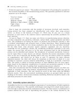
Dedicated assembly systems are special purpose, fully mechanized or automated systems for
composing previously manufactured components and/or sub-assemblies into a complete product
of unit of a product. Typically, a number of workstations comprising automatic part-feeders and fixed
work-heads are arranged on an automatically controlled transfer system to compose the product
sequentially (see 6.3F).
Process variations
.
Feeding: presentation of a component to the robot arm end effector in the correct orientation.
Orientation can be achieved by vibratory/centrifugal bowl feeders, by receiving parts
already orientated by the supplier in pallet, magazine or by escapement mechanisms for part-
feeding.
.
Handling: bringing components and/or sub-assemblies together such that later composition can
occur using fixed work-heads and/or pick and place units.
.
Fitting: various part placement/location configurations or fastening/joining methods can be utilized,
e.g. ‘peg in hole’, adhesive bonding, staking and screwing.
.
Checking: identification of missing, incorrect, misshapen or wrongly orientated components. Also
detection of foreign bodies, part-failure and machine in-operation. Common technologies include
vision systems, tactile/pressure sensors, proximity sensors and ‘bed of nails’.
.
Transfer: typically, the various assembly operations required are carried out at separate stations,
usually built up on a work carrier, pallet or holder. Therefore, a system for transferring the partly
6.3F Dedicated assembly process.
186 Selecting candidate processes
//SYS21///INTEGRAS/B&H/PRS/FINALS_07-05-03/0750654376-CH002-1.3D – 187 – [35–248/214] 9.5.2003 2:05PM
completed assemblies from workstation to workstation is required. In general, transfer systems for
dedicated assembly are either:
.
Synchronous/indexing: moved with a fixed cycle time.
.
Non-synchronous/free-transfer: moved as required or when operation/assembly completed using
in-line or rotary systems. Can set up a buffer system using this configuration. Typically, greater
than ten components to be assembled requires a free-transfer arrangement.
Economic considerations
.
Almost totally inflexible. Fixed assembly system for one product type typically, except where
variants are based on parts missing from original design.
.
Production rates high.
.
Lead time typically months.
.
Economical for high production volumes.
.
Tooling costs high.
.
Equipment costs high.
.
Direct labor costs very low.
Typical applications
.
Electronic and electrical components and devices
.
Printed circuit boards
.
Small domestic appliances
.
Medical products
.
Automotive sub-assemblies, e.g. valves, solenoids, relays
.
Office equipment
Design aspects
.
Use DFA techniques in order to develop assemblies with optimum part-count, improved component
geometry for feeding, handling, fitting and checking, and reduce overall assembly costs.
.
Develop an assembly sequence diagram to optimize the assembly line.
.
Assess overall assembly tolerance against component tolerances in stack up.
Quality issues
.
In general, assembly problems are caused by a number of factors:
.
Components exceeding or being lower than the specified tolerances causing interference or
location stability problems
.
Component misalignment and adjustment error
.
Gross defects (malformed, missing features, wrong lengths, damage in transit, etc.)
.
Foreign matter causing contamination and blockages
.
Absence of a component due to inefficient feeding or exhausted supply
.
Incorrect components caused by wrong supply or instructions
.
Inadequate joining technology.
.
Approximately 50 per cent of all problems found in automated systems (product defects and down-
time) are due to the incoming component quality.
Dedicated assembly 187
//SYS21///INTEGRAS/B&H/PRS/FINALS_07-05-03/0750654376-CH002-1.3D – 188 – [35–248/214] 9.5.2003 2:05PM
.
It is difficult and expensive to incorporate insensitivity to component variation and faults in assembly
systems to reduce this problem. Sensing capabilities are limited in this capacity.
.
Automated or mechanized systems must be chosen in certain situations, particularly where operator
safety is paramount, for example, hazardous or toxic environments, heavy component parts or a
high repeatability requirement, causing operator fatigue.
.
It can use dedicated systems for sterile or clean environment assembly of products.
.
Repeatable accuracy of component alignment is high, typically Æ0.1 mm.
188 Selecting candidate processes
//SYS21///INTEGRAS/B&H/PRS/FINALS_07-05-03/0750654376-CH002-1.3D – 189 – [35–248/214] 9.5.2003 2:05PM
7 Joining processes
//SYS21///INTEGRAS/B&H/PRS/FINALS_07-05-03/0750654376-CH002-1.3D – 190 – [35–248/214] 9.5.2003 2:05PM
7.1 Tungsten Inert-Gas Welding (TIG)
Process description
.
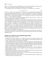
An electric arc is automatically generated between the workpiece and a non-consumable tungsten
electrode at the joint line. The parent metal is melted and the weld created with or without the
addition of a filler rod. Temperatures at the arc can reach 12 000
C. The weld area is shielded with a
stable stream of inert gas, usually argon, to prevent oxidation and contamination (see 7.1F).
Materials
.
Most non-ferrous metals (except zinc), commonly, aluminum, nickel, magnesium and titanium
alloys, copper and stainless steel. Carbon steels, low alloy steels, precious metals and refractory
alloys can also be welded. Dissimilar metals are difficult to weld.
Process variations
.
Portable manual or automated a.c. or d.c. systems. a.c commonly used for welding aluminum and
magnesium alloys.
.
Pure helium or more commonly, a helium/argon mix is used as the shielding gas for metals with high
thermal conductivity, for example copper, or material thickness greater than 6 mm giving increased
weld rates and penetration.
.
Pulsed TIG: excellent for thin sheet or parts with dissimilar thickness (low heat input).
.
TIG spot welding: used on lap joints in thin sheets.
7.1F Tungsten inert-gas welding process.
190 Selecting candidate processes
//SYS21///INTEGRAS/B&H/PRS/FINALS_07-05-03/0750654376-CH002-1.3D – 191 – [35–248/214] 9.5.2003 2:05PM
Economic considerations
.
Weld rates vary from 0.2 m/min for manual welding to 1.5 m/min for automated systems.
.
Automation is suited to long lengths of continuous weld in the same plane.
.
Automation is relatively inexpensive if no filler is required, i.e. use of close fitting parts.
.
Process is suited to sheet thickness less than 4 mm, heavier gauges become more expensive due to
argon cost and decreased production rate. Helium/argon gas is expensive but may be viable due to
increased production rate.
.
It is economical for low production runs. Can be used for one-offs.
.
Tooling costs are low to moderate.
.
Equipment costs are moderate.
.
Direct labor costs are moderate to high. Highly skilled labor required for manual welding. Setup
costs can be high for fabrications using automated welding.
.
Finishing costs are low generally. There is no slag produced at the weld area, however, some
grinding back of the weld may be required.
Typical applications
.
Chemical plant pipe work
.
Nuclear plant fabrications
.
Aerospace structures
.
Sheet-metal fabrication
Design aspects
.
Design complexity is high.
.
Typical joint designs possible using TIG are: butt, lap, fillet and edge (see Appendix B – Weld Joint
Configurations).
.
Design joints using minimum amount of weld, i.e. intermittent runs and simple or straight contours,
although TIG is suited to automated contour following.
.
Design parts to give access to the joint area, for vision, electrodes, filler rods, cleaning, etc.
.
Wherever possible horizontal welding should be designed for, however, TIG welding is suited to
most welding positions.
.
Sufficient edge distances should be designed for. Avoid welds meeting at end of runs.
.
Balance the welds around the fabrication’s neutral axis where possible.
.
Distortion can be reduced by designing symmetry in parts to be welded along weld lines.
.
The fabrication sequence should be examined with respect to the above.
.
Provision for the escape of gases and vapors in the design is important.
.
Minimum sheet thickness ¼ 0.2 mm.
.
Maximum thickness, commonly:
.
Copper and refractory alloys ¼ 3mm
.
Carbon, low alloy and stainless steels; magnesium and nickel alloys ¼ 6mm
.
Aluminum and titanium alloys ¼ 15 mm.
.
Multiple weld runs required on sheet thickness !5 mm.
.
Unequal thicknesses are difficult.
Tungsten Inert-Gas Welding (TIG) 191
//SYS21///INTEGRAS/B&H/PRS/FINALS_07-05-03/0750654376-CH002-1.3D – 192 – [35–248/214] 9.5.2003 2:05PM
Quality issues
.
Clean, high quality welds with low distortion can be produced.
.
Access for weld inspection important, e.g. Non-Destructive Testing (NDT).
.
Joint edge and surface preparation important. Contaminates must be removed from the weld area to
avoid porosity and inclusions.
.
A heat affected zone always present. Some stress relieving may be required for restoration of
materials’ original physical properties.
.
Not recommended for site work in wind where the shielding gas may be gusted.
.
Control of arc length important for uniform weld properties and penetration.
.
Need for jigs and fixtures to keep joints rigid during welding and subsequent cooling to reduce
distortion on large fabrications.
.
Backing strips can be used for avoiding excess penetration, but at added cost and increased setup
times.
.
Selection of correct filler rod important (where required).
.
Care needed to keep filler rod within the shielding gas to prevent oxidation.
.
Workpiece and filler rod must be away from the tungsten electrode to prevent contamination which
can cause an unstable arc.
.
Shielding gas must be kept on for a second or two to allow tungsten electrode to cool and prevent
oxidation.
.
Tungsten inclusions can contaminate finished welds.
.
Welding variables should be preset and controlled during production.
.
Automation reduces the ability to weld mating parts with inherent size and shape variations; reduced
by automation however, it does reduce distortion, improve reproduction and produces fewer welding
defects.
.
‘Weldability’ of the material important and combines many of the basic properties that govern the
ease with which a material can be welded and the quality of the finished weld, i.e. porosity and
cracking. Material composition (alloying elements, grain structure and impurities) and physical
properties (thermal conductivity, specific heat and thermal expansion) are some important attributes
which determine weldability.
.
Surface finish of weld excellent.
.
Fabrication tolerances typically Æ0.5 mm.
192 Selecting candidate processes
//SYS21///INTEGRAS/B&H/PRS/FINALS_07-05-03/0750654376-CH002-1.3D – 193 – [35–248/214] 9.5.2003 2:05PM
7.2 Metal Inert-Gas Welding (MIG)
Process description
.
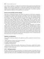
An electric arc is manually created between the workpiece and a consumable wire electrode at the
joint line. The parent metal is melted and the weld created with the continuous feed of the wire which
acts as the filler metal. The weld area is shielded with a stable stream of argon or CO
2
to prevent
oxidation and contamination (see 7.2F).
Materials
.
Carbon, low alloy and stainless steels. Most non-ferrous metals (except zinc) are also weldable;
aluminum, nickel, magnesium and titanium alloys and copper. Refractory alloys and cast iron can
also be welded. Dissimilar metals are difficult to weld.
Process variations
.
Portable semi-automatic (manually operated) or fully automated d.c. systems and robot mounted.
.
Three types of metal transfer to the weld area: dip and pulsed transfer use low current for positional
welding (vertical, overhead) and thin sheet; spray transfer uses high currents for thick sheet and
high deposition rates, typically for horizontal welding.
.
Shielding gases: pure CO
2
or argon/CO
2
mix commonly used for carbon and low alloy steels, or a
mix of argon/helium, also used for nickel alloys and copper. Pure argon is used for aluminum alloys.
High chromium steels use an argon/O
2
mix.
.
MIG spot welding: used on lap joints.
.
Flux Cored Arc Welding (FCAW): uses a wire containing a flux and gas generating compounds for
self-shielding, although flux-cored wire is preferred with additional shielding gas for certain con-
ditions. Limited to carbon steels and lower welding rates.
7.2F Metal inert-gas welding process.
Metal Inert-Gas Welding (MIG) 193
//SYS21///INTEGRAS/B&H/PRS/FINALS_07-05-03/0750654376-CH002-1.3D – 194 – [35–248/214] 9.5.2003 2:05PM
Economic considerations
.
Weld rates from 0.2 m/min for manual welding to 15 m/min for automated setups.
.
Production costs reduced by high weld deposition rates with continuous operation.
.
Well suited to traversing automated and robotic systems.
.
Choice of electrode wire (10.5–11.5 mm) and shielding gas important cost considerations.
.
Economical for low production runs. Can be used for one-offs.
.
Tooling costs low to moderate.
.
Equipment costs low to moderate, depending on degree of automation.
.
Direct labor costs moderate to high. Skill level required is less than TIG.
.
Finishing costs low generally. There is no slag produced at the weld area, however, some grinding
back of the weld may be required.
Typical applications
.
General fabrication
.
Structural steelwork
.
Automobile bodywork
Design aspects
.
All levels of complexity possible.
.
Typical joint designs possible using MIG: butt, lap, fillet and edge. MIG excellent for vertical and
overhead welding (see Appendix B – Weld Joint Configurations).
.
Design joints using minimum amount of weld, i.e. intermittent runs and simple or straight contours
wherever possible.
.
Welds should be balanced around the fabrication’s neutral axis where possible.
.
Design parts to give access to the joint area, for vision, electrodes, filler rods, cleaning, etc. MIG
good for welds inaccessible by other methods.
.
Sufficient edge distances should be designed for and avoid welds meeting at the end of runs.
.
Provision for the escape of gases and vapors in the design important.
.
Distortion can be reduced by designing symmetry in parts to be welded along weld lines.
.
The fabrication sequence should be examined with respect to the above.
.
Minimum sheet thickness ¼ 0.5 mm (6 mm for cast iron).
.
Maximum thickness, commonly:
.
Carbon, low alloy and stainless steels; cast iron, aluminum, magnesium, nickel, titanium alloys
and copper ¼ 80 mm
.
Refractory alloys ¼ 6 mm.
.
Multiple weld runs required on sheet thicknesses !5 mm.
.
Unequal thicknesses possible.
Quality issues
.
Clean, high quality welds with low distortion can be produced.
.
Access for weld inspection important, e.g. Non-Destructive Testing (NDT).
.
Joint edge and surface preparation important. Contaminates must be removed from the weld area to
avoid porosity and inclusions.
194 Selecting candidate processes
//SYS21///INTEGRAS/B&H/PRS/FINALS_07-05-03/0750654376-CH002-1.3D – 195 – [35–248/214] 9.5.2003 2:05PM
.
Shielding gas chosen to suit parent metal, i.e. it must not react when welding.
.
Wire electrode must closely match the composition of the metals being welded.
.
Slag created when using a flux-cored wire may aid the control of the weld profile and commonly
used for site work (windy conditions where the shielding gas may be gusted or positional welding)
and large fillet welds.
.
A heat affected zone always present. Some stress relieving may be required for restoration of
materials original physical properties.
.
Cracking may be experienced when welding high alloy steels.
.
Self-adjusting arc length reduces skill level required and increases weld uniformity.
.
Backing strips can be used for avoiding excess penetration, but at added cost and increased setup times.
.
Need for jigs and fixtures to keep joints rigid during welding and subsequent cooling to reduce
distortion on large fabrications.
.
Welding variables should be preset and controlled during production.
.
Automation can limit the ability to weld mating parts with large size and shape variations, however,
the use of dedicated tooling does reduce distortion, improve reproduction and produces fewer
welding defects.
.
‘Weldability’ of the material important and combines many of the basic properties that govern the
ease with which a material can be welded and the quality of the finished weld, i.e. porosity and
cracking. Material composition (alloying elements, grain structure and impurities) and physical
properties (thermal conductivity, specific heat and thermal expansion) are some important attributes
which determine weldability.
.
Surface finish of weld good.
.
Fabrication tolerances typically Æ0.5 mm.
Metal Inert-Gas Welding (MIG) 195
//SYS21///INTEGRAS/B&H/PRS/FINALS_07-05-03/0750654376-CH002-1.3D – 196 – [35–248/214] 9.5.2003 2:05PM
7.3 Manual Metal Arc Welding (MMA)
Process description
.
An electric arc is created between a consumable electrode and the workpiece at the joint line. The
parent metal is melted and the weld created with the manual feed of the electrode along the weld
and downwards as the electrode is being consumed. Simultaneously, a flux on the outside of the
electrode melts covering the weld pool and generates a gas shielding it from the atmosphere and
preventing oxidation (see 7.3F).
Materials
.
Carbon, low alloy and stainless steels; nickel alloys and cast iron typically. Welding of non-ferrous
metals is not recommended, but occasionally performed. Dissimilar metals are difficult to weld.
Process variations
.
Manual d.c. and a.c. sets. Only a few fluxes give stable operation with a.c.
.
Large selection of electrode materials with a variety of flux types for the welding of different metals
and properties required. Core sizes are between 11.6 and 19.5 mm and the electrode length is
usually 460 mm.
.
Stud Arc Welding (SW): for welding pins and stud bolts to structures for subsequent fastening
operations. Uses the pin or stud as a consumable electrode to join to the workpiece at one end.
Portable semi-automatic or static automated equipment available.
Economic considerations
.
Weld rates up to 0.2 m/min.
.
Most flexible of all welding processes.
7.3F Manual metal arc welding process.
196 Selecting candidate processes
//SYS21///INTEGRAS/B&H/PRS/FINALS_07-05-03/0750654376-CH002-1.3D – 197 – [35–248/214] 9.5.2003 2:05PM
.
Manually performed typically, although some automation possible.
.
Can weld a variety of metals by simply changing the electrode.
.
More power required for a.c. welding than d.c. welding.
.
Suitable for site work. Welding can be performed up to 20 m away from power supply.
.
Non-continuous process. Frequent changes of electrode are required.
.
Economical for low production runs. Can be used for one-offs.
.
Tooling costs low. Need for jigs and fixtures not as important as other methods and less accuracy
required in setting up.
.
Equipment costs low.
.
Direct labor costs high. Skill level required is higher than MIG.
.
Finishing costs high relative to other welding processes. Slag produced at the weld area, which must
be removed during runs and some grinding back of the weld, may be required. Weld spatter often
covers the surface which may need cleaning.
Typical applications
.
Pressure vessels
.
Structural steelwork
.
Shipbuilding
.
Pipework
.
Machine frame fabrication
.
Maintenance
Design aspects
.
All levels of complexity possible.
.
Typical joint designs possible using MMA: butt, lap, fillet and edge in heavier sections (see Appendix
B – Weld Joint Configurations).
.
Suitable for all welding positions.
.
Design joints using minimum amount of weld, i.e. intermittent runs and simple or straight contours
wherever possible.
.
Balance the welds around the fabrication’s neutral axis.
.
Distortion can be reduced by designing symmetry in parts to be welded along weld lines.
.
Design parts to give access to the joint area, for vision, electrodes, filler rods, cleaning, etc. MMA
excellent for welds inaccessible by other methods.
.
Sufficient edge distances should be designed for. Avoid welds meeting at end of runs.
.
Provision for the escape of gases and vapors in the design important.
.
The fabrication sequence should be examined with respect to the above.
.
Minimum thickness ¼ 1.5 mm (6 mm for cast iron).
.
Maximum sheet thickness, commonly for carbon, low alloy and stainless steels, nickel alloys and
cast iron ¼ 200 mm.
.
Multiple weld runs required on sheet thicknesses !10 mm.
.
Unequal thicknesses difficult.
Quality issues
.
Moderate to high quality welds with moderate, but acceptable levels of distortion can be produced.
.
Quality and consistency of weld related to skill of welder to maintain correct arc length and burn-off
rate.
Manual Metal Arc Welding (MMA) 197
//SYS21///INTEGRAS/B&H/PRS/FINALS_07-05-03/0750654376-CH002-1.3D – 198 – [35–248/214] 9.5.2003 2:05PM
.
Access for weld inspection important, e.g. NDT.
.
Joint edge and surface preparation important. Contaminates must be removed from the weld area to
avoid porosity and inclusions after each pass.
.
A heat affected zone always present. Some stress relieving may be required for restoration of
materials original physical properties.
.
Need for jigs and fixtures to keep joints rigid during welding and subsequent cooling to reduce
distortion on large fabrications.
.
Backing strips can be used for avoiding excess penetration, but at added cost and increased setup
times.
.
Can alter composition of weld by addition of alloying elements in the electrode. Addition of deoxi-
dants in the flux minimizes carbon loss, which reduces weld strength.
.
Electrodes must be dry and free from oil and grease to prevent weld contamination.
.
Low hydrogen electrodes should be used when welding high carbon steels to reduce chance of
hydrogen cracking.
.
The protective slag can help the weld to keep its shape during positional welding.
.
Weld ideally left to cool to room temperature before the slag removed.
.
When the electrode’s length reduced to approximately 50 mm it should be replaced.
.
Welding current should be maintained during welding with a stable power supply.
.
Arc deflection can sometimes occur with d.c. supplies, especially in magnetized metals. The work-
piece may need demagnetizing or the return cable repositioned.
.
Pre-heating of workpiece can reduce porosity and hydrogen cracking.
.
‘Weldability’ of the material important and combines many of the basic properties that govern the
ease with which a material can be welded and the quality of the finished weld, i.e. porosity and
cracking. Material composition (alloying elements, grain structure and impurities) and physical
properties (thermal conductivity, specific heat and thermal expansion) are some important attributes
which determine weldability.
.
Surface finish of weld fair to good. Weld spatter often covers the surface.
.
Fabrication tolerances typically Æ1 mm.
198 Selecting candidate processes
//SYS21///INTEGRAS/B&H/PRS/FINALS_07-05-03/0750654376-CH002-1.3D – 199 – [35–248/214] 9.5.2003 2:05PM
7.4 Submerged Arc Welding (SAW)
Process description
.
A blanket of flux is fed from a hopper in advance of an electric arc created between a consumable
electrode wire and the workpiece at the joint line. The arc melts the parent metal and the wire
creates the weld as it is automatically fed downwards and traversed along the weld, or the work is
moved under welding head. The flux shields the weld pool from the atmosphere preventing oxida-
tion. Any flux that is not used is recycled (see 7.4F).
Materials
.
Carbon, low alloy and stainless steels, and some nickel alloys.
.
Dissimilar metals are difficult to weld.
Process variations
.
Self-contained, mainly automated a.c. or d.c. systems with up to three welding heads.
.
Can have portable traversing welding unit using a wheeled buggy (for long welds on ship’s
deck plates for example), self-propelled traversing unit on a gantry or moving head type (for
shorter weld lengths) and fixed head where the work rotates under the welding unit (for pressure
vessels).
.
Copper-coated electrode wire can be solid or tubular. Tubular is used to supply the weld with
additional alloying elements. Wire sizes range from 10.8 to 19.5 mm.
.
Can use a strip electrode for surfacing to improve corrosion resistance (pressure vessels) or for
hardfacing parts subject to wear (bulk materials handling chute).
7.4F Submerged arc welding process.
Submerged Arc Welding (SAW) 199
//SYS21///INTEGRAS/B&H/PRS/FINALS_07-05-03/0750654376-CH002-1.3D – 200 – [35–248/214] 9.5.2003 2:05PM
.
Fluxes available in powdered or granulated form, either neutral or basic. Neutral fluxes used for low
carbon steel and basic fluxes for higher carbon steels.
.
Bulk welding: uses an iron powder placed in the joint gap in advance of the flux and electrode to
increase deposition rates.
.
For thin sections can use a flux-coated electrode wire.
Economic considerations
.
Highest weld deposition rate of all arc welding processes.
.
Speeds ranging 0.1 to 5 m/min.
.
Economic for straight, continuous welds on thick plate using single or multiple runs.
.
High power consumption offset by high productivity.
.
Economical for low production runs. Can be used for one-offs.
.
Tooling costs low to moderate. Need for jigs and fixtures important for accurate joint align-
ment.
.
Equipment costs moderate to high.
.
Direct labor costs low to moderate. Skill level required low to moderate.
.
Flux handling costs can be high.
.
Finishing costs moderate to high. Slag produced at the weld area needs to be removed.
Typical applications
.
Ships
.
Bridges
.
Pressure vessels
.
Structural steelwork
.
Pipework
Design aspects
.
Design complexity limited.
.
Typical joint designs possible using SAW: butt and fillet in heavier sections (see Appendix B – Weld
Joint Configurations).
.
Suitable for horizontal welding, but can perform vertical welding with special copper side plates to
retain flux and mold the weld pool.
.
Welds should be designed with straight runs.
.
Minimum sheet thickness ¼ 5 mm (6 mm for nickel alloys).
.
Maximum sheet thickness, commonly:
.
Carbon, low alloy and stainless steels ¼ 300 mm
.
Nickel alloys ¼ 20 mm.
.
Multiple weld runs required on sheet thicknesses !40 mm.
.
Unequal thicknesses very difficult.
Quality issues
.
High quality welds can be produced with low levels of distortion due to fast welding rates.
.
Good weld uniformity and properties, although on large deposit welds a coarse grain structure is
formed giving inferior weld toughness.
200 Selecting candidate processes
//SYS21///INTEGRAS/B&H/PRS/FINALS_07-05-03/0750654376-CH002-1.3D – 201 – [35–248/214] 9.5.2003 2:05PM
.
Access for weld inspection important, e.g. NDT.
.
Large weld beads can cause cracking. Weld penetration can be controlled by using a backing strip
when using high currents.
.
Joint edge and surface preparation important. Contaminates must be removed from the weld area to
avoid porosity and inclusions on each pass.
.
A heat affected zone always present. Some stress relieving may be required for restoration of
materials original physical properties.
.
Can alter composition of weld by addition of alloying elements in the electrode.
.
Flux must be clean and free from moisture to prevent weld contamination.
.
Weld ideally left to cool to room temperature to allow the slag to peel off.
.
Welding variables automatically controlled. Monitoring of welding voltage is used to control arc
length through varying the wire feed rate, and thereby improving weld quality.
.
Pre-heating of workpiece can reduce porosity and hydrogen cracking, especially on high carbon
steels.
.
‘Weldability’ of the material important and combines many of the basic properties that govern the
ease with which a material can be welded and the quality of the finished weld, i.e. porosity and
cracking. Material composition (alloying elements, grain structure and impurities) and physical
properties (thermal conductivity, specific heat and thermal expansion) are some important attributes
which determine weldability.
.
Surface finish of weld good.
.
Fabrication tolerances typically Æ2 mm.
Submerged Arc Welding (SAW) 201
//SYS21///INTEGRAS/B&H/PRS/FINALS_07-05-03/0750654376-CH002-1.3D – 202 – [35–248/214] 9.5.2003 2:05PM
7.5 Electron Beam Welding (EBW)
Process description
.
A controlled high intensity beam of electrons (10.5–11 mm) is directed to the joint area of the work
(anode) by an electron gun (cathode), where fusion of the base material takes place. The operation
takes place in a vacuum, and the work is traversed under the electron beam typically (see 7.5F).
Materials
.
Most metals and combination of metals weldable, including low to high carbon and alloy steels,
aluminum, titanium, copper, refractory and precious metals.
.
Copper alloys and stainless steel difficult to weld. Cast iron, lead or zinc alloys are not weldable.
.
Metals that experience gas evolution or vaporization on welding difficult.
Process variations
.
High-vacuum (most common), semi-vacuum and atmospheric (out-of-vacuum) equipment
available, depending on type of work, size and location.
.
Semi-vacuum setup used for transportable equipment. Only the area to be welded is surrounded by
a vacuum using suction cups.
.
Joint advanced under beam for high-vacuum EBW, but for short weld lengths, the beam can be moved
along the joint using magnetic coils, rather than the work under the beam on a traversing system.
.
EBM (see 5.3): an electron gun is used to generate heat and evaporating the workpiece surface for
fusion.
.
The electron beam process can also be used for cutting, profiling, slotting and surface hardening,
using the same equipment by varying process parameters.
7.5F Electron beam welding process.
202 Selecting candidate processes
//SYS21///INTEGRAS/B&H/PRS/FINALS_07-05-03/0750654376-CH002-1.3D – 203 – [35–248/214] 9.5.2003 2:05PM
Economic considerations
.
Weld rates ranging 0.2–2.5 m/min.
.
Production rates range from 10–100/h using high-vacuum equipment.
.
Lead times can be several weeks.
.
Setup times can be short, but the time to create a vacuum in the chamber at each loading cycle an
important consideration.
.
High flexibility. Possible t o perform many operations on same machine b y varying process parameters.
.
Full automation of process possible and gives best results.
.
Economical for low to moderate production runs.
.
Material utilization excellent.
.
High power consumption.
.
Tooling costs very high.
.
Equipment costs very high.
.
Direct labor varies depending on level of automation.
.
No finishing needed typically.
Typical applications
.
Aerospace assemblies (turbine vanes, filters, high pressure pump bodies)
.
Automotive assemblies (crankshaft, gears, valves, bearings)
.
Machine parts
.
Instrumentation devices
.
Pipes
.
Reactor shells
.
Hermetic sealing of assemblies
.
Medical implants
.
Bimetallic saw blades
.
Repair work
Design aspects
.
Typical joint designs possible using EBW: butt, fillet and lap (see Appendix B – Weld Joint Config-
urations). Horizontal welding position is the most suitable.
.
Path to joint area from the electron beam gun must be a straight line.
.
Beam and joint must be aligned precisely.
.
Depth to width ratio can exceed 20:1.
.
Balance the welds around the fabrication’s neutral axis.
.
Size limited by vacuum chamber dimensions unless semi-vacuum equipment used. Maximum
height of work in a chamber is 1.2 m typically.
.
Possible to weld thin and delicate sections due to no mechanical processing forces.
.
Maximum thickness (dependent on vacuum integrity):
.
Aluminum and magnesium alloys ¼ 450 mm
.
Carbon, low alloy and stainless steels ¼ 300 mm
.
Copper alloys ¼ 100 mm.
.
Minimum thickness ¼ 0.05 mm.
.
Single pass maximum ¼ 75 mm.
.
Highly dissimilar thicknesses commonly welded.
Electron Beam Welding (EBW) 203