Process Selection - From Design to Manufacture Episode 2 Part 1 ppsx
Bạn đang xem bản rút gọn của tài liệu. Xem và tải ngay bản đầy đủ của tài liệu tại đây (1.34 MB, 20 trang )
//SYS21///INTEGRAS/B&H/PRS/FINALS_07-05-03/0750654376-CH002-1.3D – 164 – [35–248/214] 9.5.2003 2:05PM
.
Removal rate can be increased with the expense of a poorer surface finish.
.
Surface detail good.
.
Surface roughness values ranging 0.4–25 mm Ra. Dependent on current density, material being
machined and rate of removal.
.
Achievable tolerances ranging Æ0.01–Æ0.125 mm. (Process capability charts have not been
included. Capability is not primarily driven by characteristic dimension but by the material being
processed.)
164 Selecting candidate processes
//SYS21///INTEGRAS/B&H/PRS/FINALS_07-05-03/0750654376-CH002-1.3D – 165 – [35–248/214] 9.5.2003 2:05PM
5.2 Electrochemical Machining (ECM)
Process description
.
Workpiece material is removed by electrolysis. A tool, usually copper (Àve electrode), of the desired
shape is kept a fixed distance away from the electrically conductive workpiece ( þve electrode),
which is immersed in a bath containing a fast flowing electrolyte and connected to a power supply.
The workpiece is then dissolved by an electrochemical reaction to the shape of the tool. The
electrolyte also removes the ‘sludge’ produced at the workpiece surface (see 5.2F).
Materials
.
Any electrically conductive material irrespective of material hardness, commonly, tool steels, nickel
alloys and titanium alloys. Ceramics and copper alloys are also processed occasionally.
Process variations
.
Electrochemical Grinding (ECG): combination of electrochemical reaction and abrasive machining
of workpiece.
.
Electrochemical drilling: for the production of deep, small diameter holes.
.
Electrochemical polishing: for deburring and honing.
Economic considerations
.
Production rates moderate.
.
Material removal rates typically 50–250 mm
3
/s.
.
Linear penetration rates up to 0.15 mm/s.
5.2F Electrochemical machining process.
Electrochemical Machining (ECM) 165
//SYS21///INTEGRAS/B&H/PRS/FINALS_07-05-03/0750654376-CH002-1.3D – 166 – [35–248/214] 9.5.2003 2:05PM
.
Dependent on current density, electrolyte and gap between tool and workpiece.
.
High power consumption.
.
Lead time can be several weeks. Tools are very complex.
.
Setup times can be short.
.
Material utilization very poor. Scrap material cannot be recycled.
.
Disposal of sludge and chemicals used can be costly and hazardous.
.
High degree of automation possible.
.
Economical for moderate to high production runs.
.
Tooling costs very high. Dedicated tooling.
.
Equipment costs generally high.
.
Direct labor costs low to moderate.
Typical applications
.
Hole (circular and non-circular) production, profiling and contouring of components
.
Engine casting features
.
Turbine blade shaping
.
Dies for forging
.
Gun barrel rifling
.
Honeycomb structures and irregular shapes
.
Burr free parts
.
Deep holes
Design aspects
.
High degree of shape complexity possible, limited only by ability to produce tool shape.
.
Can be used for material susceptible to heat damage.
.
Suitable for small diameter, deep holes with length to diameter ratios up to 50:1.
.
Suitable for parts affected by thermal processes.
.
Undercuts possible with specialized tooling.
.
Possible to machine thin and delicate sections due to no processing forces.
.
Cannot produce perfectly sharp corners.
.
Minimum radius ¼ 0.05 mm.
.
Minimum hole size ¼ 10.1 mm.
Quality issues
.
Burr free part production.
.
Produces slightly tapered holes, especially if deep, and some overcut possible.
.
Finishing cuts are made at low material removal rates.
.
Deep holes will have tapered walls.
.
No stresses introduced, either, thermal or mechanical.
.
Virtually no tool wear.
.
Arcing may cause tool damage.
.
Some electrolyte solutions can be corrosive to tool, workpiece and equipment.
.
Surface detail good.
.
Surface roughness values ranging 0.2–12.5 mm Ra. Dependent on current density and material
being machined.
.
Achievable tolerances ranging Æ 0.013–Æ0.5 mm. (Process capability charts have not been included.
Capability is not primarily driven by characteristic dimension but by the material being processed.)
166 Selecting candidate processes
//SYS21///INTEGRAS/B&H/PRS/FINALS_07-05-03/0750654376-CH002-1.3D – 167 – [35–248/214] 9.5.2003 2:05PM
5.3 Electron Beam Machining (EBM)
Process description
.
An electron gun bombards the workpiece with electrons up to 80 per cent the speed of light
generating localized heat and evaporating the workpiece surface. Magnetic lenses focus the
electron beam, and electromagnetic coils control its position. The workpiece is contained within a
vacuum chamber typically (see 5.3F).
Materials
.
Any material regardless of its type, electrical conductivity and hardness.
Process variations
.
Electron Beam Welding (EBW) (see 7.5): used to weld a range of material of varying thicknesses
giving a small weld area and heat affected zone, with no flux or filler.
.
The electron beam process can also be used for cutting, profiling, slotting and surface hardening,
using the same equipment by varying process parameters.
Economic considerations
.
Production rates dependent on size of vacuum chamber and by the ability to process a number of
parts in batches at each loading cycle (less than 1 s per hole cycle time on thin workpieces).
.
Parts should closely match size of chamber.
.
Material removal rates low, typically 10 mm
3
/min. Penetration speeds up to 600 mm/min possible.
.
Lead times can be several weeks.
5.3F Electron beam machining process.
Electron Beam Machining (EBM) 167
//SYS21///INTEGRAS/B&H/PRS/FINALS_07-05-03/0750654376-CH002-1.3D – 168 – [35–248/214] 9.5.2003 2:05PM
.
Setup times can be short, but the time to create a vacuum in the chamber at each loading cycle is an
important consideration.
.
Material utilization good.
.
High degree of automation possible.
.
High energy consumption process.
.
Economical with low to moderate production runs for thin parts requiring small cuts.
.
Tooling costs very high.
.
Equipment costs very high.
.
Direct labor costs high. Skilled labor required.
.
Finishing costs very low.
Typical applications
.
Multiple small diameter holes in very thin and thick materials
.
Injector nozzle holes
.
Small extrusion die holes
.
Irregular shaped holes and slots
.
Engraving
.
Features in silicon wafers for the electronics industry
Design aspects
.
Electron beam path can be programmed to produce the desired pattern.
.
Suitable for small diameter, deep holes with length to diameter ratios up to 100:1.
.
Possible to machine thin and delicate sections due to no mechanical processing forces.
.
Sharp corners difficult to produce.
.
Better to have more small holes requiring less heat than a few large holes requiring considerable
heat.
.
Maximum thickness ¼ 150 mm.
.
Minimum hole size ¼ 10.01 mm.
Quality issues
.
Localized thermal stresses giving very small heat affected zones, small recast layers and low
distortion of thin parts possible.
.
Integrity of vacuum important. Beam dispersion occurs due to electron collision with air molecules.
.
The reflectivity of the workpiece surface important. Dull and unpolished surfaces are preferred.
.
Hazardous X-rays produced during processing which require lead shielding.
.
Produces slightly tapered holes, especially if deep holes are required.
.
Critical parameters to control during process: voltage, beam current, beam diameter and work
speed.
.
The melting temperature of the material may also have a bearing on quality of surface finish.
.
Surface roughness values ranging 0.4–6.3 mm Ra.
.
Achievable tolerances ranging Æ0.013–Æ0.125 mm. (Process capability charts have not been
included. Capability is not primarily driven by characteristic dimension.)
168 Selecting candidate processes
//SYS21///INTEGRAS/B&H/PRS/FINALS_07-05-03/0750654376-CH002-1.3D – 169 – [35–248/214] 9.5.2003 2:05PM
5.4 Laser Beam Machining (LBM)
Process description
.
A pulsed beam of coherent monochromatic light of high power density, commonly known as a laser
(Light Amplification by Stimulated Emission of Radiation), is focused on to the workpiece surface
causing it to vaporize locally. The material then leaves the surface in the vaporized or liquid state at
high velocity (see 5.4F).
Materials
.
Most materials, but dependent on thermal diffusivity and to a lesser extent the optical characteristics
of material, rather than chemical composition, electrical conductivity or hardness.
Process variations
.
Many types of laser are available, used for different applications. Common laser types available are:
CO
2
, Nd:YAG, Nd:glass, ruby and excimer. Depending on economics of process, pulsed and
continuous wave modes are used.
.
High pressure gas streams are used to enhance the process by aiding the exothermic reaction
process, keeping the surrounding material cool and blowing the vaporized or molten material and
slag away from the workpiece surface.
.
Laser beam machines can also be used for cutting, surface hardening, welding (LBW) (see 7.6),
drilling, blanking, honing, engraving and trimming, by varying the power density.
Economic considerations
.
Production rates are moderate to high; 100 holes/s possible for drilling.
.
Higher material removal rate than conventional machining.
.
Material removal rates typically 5 mm
3
/s and cutting speeds 70 mm/s.
.
High power consumption.
5.4F Laser beam machining process.
Laser Beam Machining (LBM) 169
//SYS21///INTEGRAS/B&H/PRS/FINALS_07-05-03/0750654376-CH002-1.3D – 170 – [35–248/214] 9.5.2003 2:05PM
.
Lead times can be short, typically weeks.
.
Setup times short.
.
Material utilization good.
.
High degree of automation possible.
.
High flexibility. Integration with CNC punching machines is popular giving greater design freedom.
.
Possible to perform many operations on same machine by varying process parameters.
.
Economical for low to moderate production runs.
.
Tooling costs very high.
.
Equipment costs very high.
.
Direct labor costs medium to high. Some skilled labor required.
Typical applications
.
For holes, profiling, scribing, engraving and trimming
.
Non-standard shaped holes, slots and profiling
.
Prototype parts
.
Small diameter lubrication holes
.
Features in silicon wafers in the electronics industry
Design aspects
.
Laser can be directed, shaped and focused by reflective optics permitting high spatial freedom in
2-dimensions and 3-dimensions with special equipment.
.
Suitable for small diameter, deep holes with length to diameter ratios up to 50:1.
.
Special techniques required to drill blind and stepped holes, but not accurate.
.
Minimal work holding fixtures required.
.
Sharp corners possible, but radii should be provided for in the design.
.
Maximum thicknesses: mild steel ¼ 25 mm, stainless steel ¼ 13 mm, aluminum ¼ 10 mm.
.
Maximum hole size (not profiled) ¼ 1.3 mm.
.
Minimum hole size ¼ 10.005 mm.
Quality issues
.
Difficulty of material processing is dictated by how close the material’s boiling and vaporization
points are.
.
Localized thermal stresses, heat affected zones, recast layers and distortion of very thin parts may
be produced. Recast layers can be removed if undesirable.
.
No cutting forces, so simple fixtures can be used.
.
It is possible to machine thin and delicate sections due to no mechanical contact.
.
The cutting of flammable materials is usually inert gas assisted. Metals are usually oxygen
assisted.
.
Control of the pulse duration is important to minimize the heat-affected zone, depth and size of
molten metal pool surrounding the cut.
.
The reflectivity of the workpiece surface is important. Dull and unpolished surfaces are preferred.
.
Hole wall geometry can be irregular. Deep holes can cause beam divergence.
.
Surface detail is fair.
.
Surface roughness values ranging 0.4–6.3 mm Ra.
.
Achievable tolerances ranging Æ0.015–Æ0.125 mm. (Process capability charts have not been
included. Capability is not primarily driven by characteristic dimension.)
170 Selecting candidate processes
//SYS21///INTEGRAS/B&H/PRS/FINALS_07-05-03/0750654376-CH002-1.3D – 171 – [35–248/214] 9.5.2003 2:05PM
5.5 Chemical Machining (CM)
Process description
.
Selective chemical dissolution of the workpiece material by immersion in a bath containing an
etchant (usually acid or alkali solution). The areas that are not required to be etched are masked
with ‘cut and peel’ tapes, paints or polymeric materials (see 5.5F).
Materials
.
Most materials can be chemically machined with the correct chemical etchant selection, commonly:
ferrous, nickel, titanium, magnesium and copper alloys, and silicon.
Process variations
.
Chemical milling: chemical removal of material to a specified depth on large areas.
.
Chemical blanking: used for thin parts requiring penetration through thickness.
.
Photochemical blanking: uses photographic techniques to blank very thin sheets of metal, primarily
for the production of printed circuit boards.
.
Thermochemical machining: uses a hot corrosive gas.
.
Electropolishing: for removal of residual stresses in surfaces.
.
Chemical jet machining: uses a single jet of etchant.
Economic considerations
.
Production rates low to moderate. Can be improved by machining a large sheet before cutting out
the individual parts. Parts can also be etched on both sides simultaneously.
.
Linear penetration rate very slow, typically 0.0025–0.1 mm/min, but dependent on material.
5.5F Chemical machining process.
Chemical Machining (CM) 171
//SYS21///INTEGRAS/B&H/PRS/FINALS_07-05-03/0750654376-CH002-1.3D – 172 – [35–248/214] 9.5.2003 2:05PM
.
Lead times short.
.
Setup times short.
.
Material utilization poor. Scrap material cannot be recycled.
.
Disposal of chemicals used can be costly.
.
Economical for low production runs. Least economical quantity is 1.
.
Tooling costs low.
.
Equipment costs generally low.
.
Direct labor costs low.
Typical applications
.
Primarily used for weight reduction in aerospace components, panels, extrusions and forgings by
producing shallow cavities
.
Printed circuit board tracks
.
Features in silicon wafers for the electronics industry
.
Decorative panels
.
Printing plates
.
Honeycomb structures
.
Irregular contours and stepped cavities
.
Burr free parts
Design aspects
.
High degree of shape complexity possible in two-dimensions.
.
Suitable for parts affected by thermal processes.
.
Undercuts always present. The etch factor for a material is the ratio of the etched depth to the size of
undercut.
.
Controlling the size of small holes in thin sheet difficult.
.
Compensation for the undercut should be taken into account when designing the masking
template.
.
Inside edges always have radii. Outside edges have sharp corners.
.
Possible to machine thin and delicate sections due to no processing forces.
.
Minimum thickness ¼ 0.013 mm.
.
Maximum depth of cut ¼ 13 mm.
.
Maximum size ¼ 3.7 m  15 m, but dependent on bath size.
Quality issues
.
Residual stresses in the part should be removed before processing to prevent distortion.
.
Surfaces need to be clean and free from grease and scale to allow good masking adhesion and
uniform material removal.
.
Masking material should not react with the chemical etchant.
.
Parts should be washed thoroughly after processing to prevent further chemical reactions.
.
Porosity in castings/welds and intergranular defects are preferentially attacked by the etchant. This
causes surface irregularities and non-uniformities.
.
Room temperature and humidity, bath temperature and stirring need to be controlled to obtain
uniform material removal.
.
Surface detail is good.
172 Selecting candidate processes
//SYS21///INTEGRAS/B&H/PRS/FINALS_07-05-03/0750654376-CH002-1.3D – 173 – [35–248/214] 9.5.2003 2:05PM
.
Surface roughness values ranging 0.4–6.3 mm Ra and are dependent on the material being pro-
cessed.
.
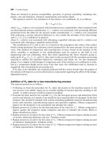
Achievable dimensional tolerances for selected process and material combinations are provided
(see 5.5CC).
5.5CC Chemical machining process capability chart.
Chemical Machining (CM) 173
//SYS21///INTEGRAS/B&H/PRS/FINALS_07-05-03/0750654376-CH002-1.3D – 174 – [35–248/214] 9.5.2003 2:05PM
5.6 Ultrasonic Machining (USM)
Process description
.
The tool, which is negative of the workpiece, is vibrated at around 20 kHz with an amplitude between
0.013 mm and 0.1 mm in an abrasive grit slurry at the workpiece surface. The workpiece material is
removed by essentially three mechanisms: hammering of the grit against the surface by the tool,
impact of free abrasive grit particles (erosion) and micro-cavitation. The slurry also removes debris
away from the surface. The tool is gradually moved down maintaining a constant gap of approxi-
mately between the tool and workpiece surface (see 5.6F).
Materials
.
Any material, however, brittle hard materials are preferred to ductile, for example, ceramics,
precious stones, tool steels, titanium and glass.
Process variations
.
Vibrations are either piezo-electric or magnetostrictive-transducer generated.
.
Tool materials vary with application and allowable tool wear during machining. Common tool
materials are: mild steel, stainless steel, tool steel, aluminum, brass and carbides (higher wear
rates are experienced with aluminum and brass).
.
Abrasive grit is available in many grades and material types. Materials commonly used are: boron
carbide, aluminum oxide, diamond and silicon carbide.
.
Liquid medium can be w ater, benzine o r oil. Higher viscosity mediums decrease material removal rates.
.
Rotary USM: a rotating diamond coated tool is used for drilling and threading, but with no abrasive
involved.
.
Ultrasonic cleaning: uses high-frequency sound waves in a liquid causing cavitation, which cleans
the surface of the component, similar to a scrubbing action. Used to remove scale, rust, etc.
5.6F Ultrasonic machining process.
174 Selecting candidate processes
//SYS21///INTEGRAS/B&H/PRS/FINALS_07-05-03/0750654376-CH002-1.3D – 175 – [35–248/214] 9.5.2003 2:05PM
Economic considerations
.
Production rates very low.
.
Material removal rates low, typically 13 mm
3
/s.
.
Linear penetration rates up to 0.4 mm/s.
.
Lead time typically days depending on complexity of tool. Special tooling required for each job.
.
Material utilization poor. Scrap material cannot be recycled.
.
High degree of automation possible.
.
Economical for low production runs. Can be used for one-offs.
.
Tooling costs high.
.
Equipment costs generally moderate.
.
Direct labor costs low to moderate.
Typical applications
.
Burr free holes and slots in hard, brittle materials
.
Complex cavities
.
Coining operations
Design aspects
.
Limited to shape of tool and control in 2-dimensions.
.
Tool and tool holder designed with mass, shape and mechanical property considerations.
.
Sharp profiles, corners and radii should be avoided as abrasive slurry erodes them away.
.
Overcut will be produced which is approximately twice the grit size.
.
Suitable for small diameter holes with length to diameter ratios typcially 3:1. Up to 4:1 using special
equipment.
.
Waste removal limits hole depths.
.
Maximum hole size ¼ 90 mm.
.
Minimum hole size ¼ 0.08 mm.
Quality issues
.
Tapering of slots and holes occurs.
.
Through holes in brittle materials should have a backing plate.
.
Amplitude and frequency of vibration, tool material, impact force, abrasive grit grade and slurry
viscosity and concentration all impact on accuracy, surface roughness and material removal rate.
.
Finishing cuts made at lower material removal rates.
.
Tool wear problematic. Tool changes can be frequent.
.
Part is burr free with no residual stresses, distortion or thermal effects.
.
Difference in wear rate between the tool and workpiece materials should be as high as possible.
.
Surface detail good.
.
Surface roughness values ranging 0.2–1.6 mm Ra.
.
Finer surface roughness values obtained with finer grit grades.
.
Achievable tolerances ranging Æ0.005–Æ0.05 mm. (Process capability charts have not been
included. Capability is not primarily driven by characteristic dimension.)
Ultrasonic Machining (USM) 175
//SYS21///INTEGRAS/B&H/PRS/FINALS_07-05-03/0750654376-CH002-1.3D – 176 – [35–248/214] 9.5.2003 2:05PM
5.7 Abrasive Jet Machining (AJM)
Process description
.
Erosive action of an abrasive in a fluid is focused to a high velocity (150–300 m/s) jet through a
sapphire nozzle. The abrasive and fractured particles are carried away from the cutting area by the
jet (see 5.7F).
Materials
.
Suitable for brittle and/or fragile materials.
.
Refractory metals, titanium alloys, ceramics, metallic honeycomb structural materials, acrylic,
composites, glass, silicon and graphite.
Process variations
.
Two systems for introducing the abrasive to the jet stream:
.
Entrainment system: pressurized water jet pulls in abrasive particles into the stream, they are
mixed in a tube and exit the nozzle.
.
Abrasive slurry system: mixing of fluid medium and abrasive particles takes place prior to
pressurization in a separate chamber to create the slurry. Higher wear rates throughout the
equipment experienced using this system, but less expensive.
.
Fluid medium: either water or a gas (air or CO
2
).
.
Abrasive types: aluminum oxide and silicon carbide use.
.
Tungsten can also be used for the nozzle, but has a higher wear rate than sapphire.
.
Nozzle orifice can be round or square.
.
Water jet machining: very high pressure focused jet of water used for cutting food, leather, paper
and foamed plastics.
.
Chemical jet machining: uses a single jet of etchant for deburring.
5.7F Abrasive jet machining process.
176 Selecting candidate processes
//SYS21///INTEGRAS/B&H/PRS/FINALS_07-05-03/0750654376-CH002-1.3D – 177 – [35–248/214] 9.5.2003 2:05PM
Economic considerations
.
Production rates moderate.
.
Material removal rates low, typically 15 mm
3
/min.
.
Penetration rate ranging from 10 to 1200 mm/min.
.
Removal rate depends on the hardness of material and process parameters.
.
Material utilization poor. Scrap material cannot be recycled.
.
Can be fully automated using robots. Added flexibility.
.
Small power requirements needed.
.
Economical for low production runs.
.
Tooling costs high.
.
Equipment costs generally high.
.
Direct labor costs low to moderate, depending on degree of automation.
Typical applications
.
Through-holes, slots and profiles in hard, brittle materials
.
For cutting, slitting, drilling, contouring, etching, cleaning, deburring and polishing
.
Electronic component etching
.
Etching and cutting glass
.
Cutting metal foils
Design aspects
.
Features limited to profiles, holes and slots.
.
Depth of cut can be increased with jet pressure.
.
Blind holes not possible.
.
Long holes have tapered walls.
.
Slot widths ranging from 0.12 to 0.25 mm.
Quality issues
.
No heat and therefore no heat affected zone. Part free from metallurgical effects and residual
stresses.
.
Minimal dust, toxicity and fire hazard, but high noise levels.
.
Less than 1 mm focus length from work should be maintained so no loss of definition and stray
abrasion occurs.
.
Minimal tool dulling.
.
Inclination of jet angle to work can be less than 90
, but at increased jet divergence on work, and
therefore less control over material being cut.
.
Abrasive size, slurry composition and flow-rate important control variables of the process for
consistency.
.
Abrasive slurry cannot be recycled due to abrasive grit blunting reducing effectiveness.
.
Abrasive can become embedded in work surface.
.
Surface detail good to excellent.
.
Surface roughness values ranging 0.1–1.6 mm Ra.
.
Surface roughness depends on abrasive particle size.
.
Achievable tolerances ranging Æ0.001–Æ0.013 mm. (Process capability charts have not been
included. Capability is not primarily driven by characteristic dimension.)
Abrasive Jet Machining (AJM) 177
//SYS21///INTEGRAS/B&H/PRS/FINALS_07-05-03/0750654376-CH002-1.3D – 178 – [35–248/214] 9.5.2003 2:05PM
//SYS21///INTEGRAS/B&H/PRS/FINALS_07-05-03/0750654376-CH002-1.3D – 179 – [35–248/214] 9.5.2003 2:05PM
6 Assembly systems
//SYS21///INTEGRAS/B&H/PRS/FINALS_07-05-03/0750654376-CH002-1.3D – 180 – [35–248/214] 9.5.2003 2:05PM
6.1 Manual assembly
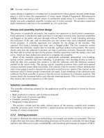
Process description
.
Manual assembly involves the composing of previously manufactured components and/or sub-
assemblies into a complete product of unit of a product, primarily performed by human operators
using their inherent dexterity, skill and judgment. The operator may be at a workstation (bench) or be
part of a transfer system that moves the product as it is being assembled. Manual assembly can be
further assisted by mechanized or automated systems for feeding, handling, fitting and checking
operations (see 6.1F).
Process variations
.
Feeding: presentation of a component to the handling equipment in the correct orientation by a
variety of methods. Parts manually taken from storage bins and then orientated by operator.
Orientation can be achieved by vibratory/centrifugal bowl feeders, parts already orientated in
pallet/magazine/strip form or use of part-feeding escapement mechanisms.
.
Handling: bringing components and/or sub-assemblies together such that later composition can
occur. Use of hands, simple lifting aids and jigs and fixtures.
.
Fitting: various part placement/location configurations or fastening/joining methods can be utilized,
e.g. ‘peg in hole’, press fit, welding, riveting, adhesive bonding, staking and screwing, using a variety
of hand operated or mechanized/electrical tools.
.
Checking: detection of missing, incorrect, misshapen or wrongly orientated components by high-
level sensing and checking capabilities of operators and mechanical/electrical aids. Also detection
of foreign bodies, part-failure and machine in-operation.
.
Transfer: typically, the various assembly operations required are carried out at separate stations,
usually built up on a work carrier, pallet or holder. Therefore, a system for transferring the partly
6.1F Manual assembly process.
180 Selecting candidate processes
//SYS21///INTEGRAS/B&H/PRS/FINALS_07-05-03/0750654376-CH002-1.3D – 181 – [35–248/214] 9.5.2003 2:05PM
completed assemblies from workstation to workstation is required. In general, the various types of
workstation/transfer system for manual assembly are:
.
Single-station: assembly at one workstation or bench where a specific or a variety of operations
are performed.
.
Continuous: work carrier flows without stopping, using conveyors (in-line, rotary dial or carousel),
overhead rail or towline.
.
Intermittent: synchronous/indexing (moved with a fixed cycle time) or non-synchronous/free-
transfer (moved as required or when operation/assembly completed by operator) using in-line or
rotary systems.
Economic considerations
.
Production rates low to moderate, depending on complexity, number and size of component parts.
These factors also dictate the degree of mechanized assistance needed.
.
Extremely flexible assembly system (many product variants) and therefore most common.
.
Lead time typically days, higher if mechanized assistance devices used.
.
Economical for low to moderate production runs. Can be used for one-offs.
.
Tooling costs low to moderate.
.
Equipment costs generally low, except where full-mechanized assistance exists.
.
Direct labor costs moderate to high. Relatively easy to train operators.
Typical applications
.
Car assembly lines
.
Internal combustion engines
.
Domestic appliances and office equipment
.
Electronic and electrical equipment
.
Machine tools
.
General fabrication
.
Toys, furniture, footwear and clothing
Design aspects
.
Use DFA techniques in order to develop assemblies with optimum part-count, improved component
geometry for feeding, handling, fitting and checking, and reduce overall assembly costs.
.
Use Poka-Yoke (mistake-proofing) techniques to help reduce operator assembly errors by prescrib-
ing component features and/or assembly procedures to aid correct assembly.
.
Develop an assembly sequence diagram to optimize the assembly line.
.
Assess overall assembly tolerance against component tolerances in stack up.
Quality issues
.
In general, assembly problems are caused by a number of factors:
.
Components exceeding or being lower than the specified tolerances
.
Component misalignment and adjustment error
.
Gross defects (malformed, missing features, wrong lengths, damage in transit, etc.)
.
Foreign matter causing contamination and blockages
.
Absence of a component due to inefficient feeding or exhausted supply
Manual assembly 181
//SYS21///INTEGRAS/B&H/PRS/FINALS_07-05-03/0750654376-CH002-1.3D – 182 – [35–248/214] 9.5.2003 2:05PM
.
Incorrect components caused by wrong supply or instructions
.
Inadequate joining technology
.
Skill of labor used.
.
Manual assembly is not suitable for harsh environments. Also, size and weight of parts to be
assembled must be considered for safety handling.
.
Operator fatigue, health and relaxation time must be considered, especially for highly repetitive
operations.
.
Assembly errors increase if components/sub-assemblies are complex, difficult to align, insert or if
there is restricted access for insertion.
.
Poor quality components can generally be sorted out during the assembly task without difficulty or
high loss through the advanced checking capabilities of human operators.
.
Repeatable accuracy of component alignment is low to moderate depending on part complexity,
typically Æ0.5 mm.
182 Selecting candidate processes
//SYS21///INTEGRAS/B&H/PRS/FINALS_07-05-03/0750654376-CH002-1.3D – 183 – [35–248/214] 9.5.2003 2:05PM
6.2 Flexible assembly
Process description
.
Flexible assembly systems use programmable, robotic devices to compose previously manufac-
tured components and/or sub-assemblies into a complete product of unit of a product. A number of
transfer mechanisms, feeding devices, robot types and end effectors can be utlilized in order to
achieve a general assembly system (see 6.2F).
Process variations
.
Robot types: variety of configurations, loading carrying capacity, working envelope, wrist degrees of
freedom and accuracy/repeatability, e.g. revolute, polar, gantry and pendulum.
.
End effectors: variety of arrangements depending on part geometry and feeding direction, flexibility,
fragility and overall part size and weight. Either pneumatic, vacuum, electromechanical or electro-
magnetic actuation of holding/gripping mechanism.
.
Feeding: presentation of a component to the robot arm end effector in the correct orientation.
Orientation can be achieved by vibratory/centrifugal bowl feeders, by receiving parts already
orientated by the supplier in pallet, magazine or by escapement mechanisms for part feeding.
.
Handling: bringing components and/or sub-assemblies together such that later composition can
occur using robot arm end effectors.
.
Fitting: various part placement/location configurations or fastening/joining methods can be utilized,
e.g. ‘peg in hole’, adhesive bonding, staking and screwing.
.
Checking: detection of missing, incorrect, misshapen or wrongly orientated components by electro-
nic vision systems, tactile/pressure sensors and proximity sensors.
.
Transfer: typically, the various assembly operations required are carried out at separate stations,
usually built up on a work carrier, pallet or holder. Therefore, a system for transferring the partly
6.2F Flexible assembly process.
Flexible assembly 183