Process Selection - From Design to Manufacture Episode 1 Part 8 doc
Bạn đang xem bản rút gọn của tài liệu. Xem và tải ngay bản đầy đủ của tài liệu tại đây (804.28 KB, 20 trang )
//SYS21///INTEGRAS/B&H/PRS/FINALS_07-05-03/0750654376-CH002-1.3D – 124 – [35–248/214] 9.5.2003 2:05PM
3.11 Powder metallurgy
Process description
.
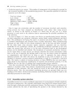
Die compaction of a blended powdered material into a ‘green’ compact which is then sintered with
heat to increase the bond strength. Usually secondary operations are performed to improve dimen-
sional accuracy, surface roughness, strength and/or porosity (see 3.11F).
Materials
.
All materials, typically metals and ceramics. Iron, copper alloys and refractory metals most common.
.
Can process materials not formable by other methods.
.
Powder production: atomization, electrolysis and chemical reduction methods.
Process variations
.
Cold die compaction: performed at room temperature. Gives high porosity and low strength.
.
Hot forging: deformation of reheated sintered compact to final density and shape.
.
Continuous compaction: for strip or sheet product. Slower than conventional rolling.
.
Isostatic compaction (hot or cold): compaction of powder in a membrane using pressurized fluid
(oil, water) or gas. Permits more uniform compaction and near-net shapes. Undercuts and reverse
tapers possible, but not transverse holes. Used for ceramics mainly.
.
Extrusion: high pressure ram forces powder through an orifice determining the section profile.
.
Injection molding: fine powder coated with thermoplastic injected into dies. Relatively complex
shapes with thin walls achievable.
.
Spark sintering: gives magnetic and electrical properties.
3.11F Powder metallurgy process.
124 Selecting candidate processes
//SYS21///INTEGRAS/B&H/PRS/FINALS_07-05-03/0750654376-CH002-1.3D – 125 – [35–248/214] 9.5.2003 2:05PM
.
Pressureless compaction: for porous components.
.
Secondary operations include: repressing, sizing and machining.
Economic considerations
.
High production rates, small parts up to 1800 pieces/hour.
.
Cycle times dictated by sintering mechanisms.
.
Lead times several weeks. Dies must be carefully designed and made.
.
Production quantities of 20 000þ preferred, but may be economic for 5000 for simple parts.
.
Material utilization very high. Less than 5 per cent lost in scrap.
.
Powders expensive to produce.
.
Automation of process common.
.
New set of die and punches required for each new product, i.e. flexibility low.
.
Tooling costs very high. Dedicated tooling.
.
Equipment costs high. Sintering equipment not dedicated though.
.
Labor costs low to moderate. Some skilled labor may be required.
.
Finishing costs generally low.
.
Final grinding may be more economical than sizing for very close tolerances.
Typical applications
.
Cutting tools
.
Small arms parts
.
Bearings
.
Filters (porous)
.
Lock components (keys, barrels)
.
Machine parts (ratchets, pawls, cams, gears)
Design aspects
.
Complexity and part size limited by powder flow through die space (powders do not follow hydro-
dynamic laws) and pressing action.
.
Near-net shapes generated.
.
Concentric, cylindrical shapes with uniform, parallel walls preferred.
.
Multiple-action tooling can be used to create complex parts.
.
Complex profiles on one side only.
.
Parts can be quenched, annealed and surface treated like wrought products to alter mechanical
properties.
.
Inert plastics can be impregnated for pressure sealing or a low melting point metal for powder
forging.
.
Densities typically between 90 per cent and 95 per cent of original material.
.
Density can be controlled for special functional properties, e.g. porosity for filters.
.
Spheres approximated. Complicated radial contours possible.
.
Marked changes in section thickness should be avoided.
.
Narrow slots, splines, long thin section, knife-edges and sharp corners should be avoided. Use
secondary processing operations.
.
Threads not possible.
.
Tapered, blind and non-circular holes, vertical knurls possible in direction of powder compaction.
.
Grooves, cutouts and off-axis holes perpendicular to the pressing direction can not be produced directly.
Powder metallurgy 125
//SYS21///INTEGRAS/B&H/PRS/FINALS_07-05-03/0750654376-CH002-1.3D – 126 – [35–248/214] 9.5.2003 2:05PM
.
Undercuts perpendicular to compaction direction not possible. Better to secondary process.
.
Radii should be as generous as possible.
.
Chamfers preferred to radii on part edges.
.
Maximum length to diameter ratio ¼ 4:1.
.
Maximum length to wall thickness ratio ¼ 8:1.
.
Inserts possible at extra cost.
.
Draft angles can be zero.
.
Minimum section can be as low as 0.4 mm, but 1.5 mm typically.
.
Sizes ranging 10 g–15 kg in weight or 4 mm
2
–0.016 m
2
in projected area.
Quality issues
.
Density and strength variations in product can occur with asymmetric shapes. Can be minimized by
die design.
.
High densities required for subsequent welding of sintered parts.
.
Porosity in sintered parts means excessive absorption of braze and solder fillers.
.
Product strength determinable by powder size, compacting pressure, sintering time and tempera-
ture, but generally, lower mechanical properties than wrought materials.
.
Can give a highly porous structure, but can be controlled and used to advantage, e.g. filters and
bearing lubricant impregnation (10–30 per cent oil by volume). Also, resin impregnation can greatly
improve machinability of sintered products.
.
Generally, lower mechanical properties than wrought materials.
.
Sharp edges on tools should be avoided. Causes excessive tool wear.
.
Remnants of contaminates at grain boundaries may act as crack initiators.
.
Oxide film may impair properties of finished part, for example: chromium and high temperature
superalloys.
.
Surface detail good.
.
Surface roughness in the range 0.2–3.2 mm Ra.
.
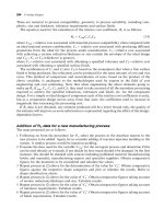
Process capability charts showing the achievable dimensional tolerances are provided (see 3.11CC).
.
Repressing, coining and sizing improves surface finish, density and dimensional accuracy. Also for
embossing.
126 Selecting candidate processes
//SYS21///INTEGRAS/B&H/PRS/FINALS_07-05-03/0750654376-CH002-1.3D – 127 – [35–248/214] 9.5.2003 2:05PM
3.11CC Powder metallurgy process capability chart.
Powder metallurgy 127
//SYS21///INTEGRAS/B&H/PRS/FINALS_07-05-03/0750654376-CH002-1.3D – 128 – [35–248/214] 9.5.2003 2:05PM
3.12 Continuous extrusion (metals)
Process description
.
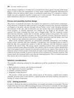
A billet of the raw material, either hot or cold, is placed into a chamber and forced through a die of
the required profile with a ram (see 3.12F).
Materials
.
Most ductile metals, for example: aluminum, copper and magnesium alloys. To a lesser degree:
zinc, lead, tin, nickel and titanium alloys, refractory metals, and carbon, low alloy and stainless
steels are processed.
Process variations
.
Forward extrusion: billet extruded by ram from behind.
.
Backward extrusion: billet displaced by advancing ram with die attached to front and extrudate
travels through the center of the ram. Limited to short lengths only. Similar to Hooker process.
.
Cold extrusion: increases friction and therefore processing energy/forces, but increases dimen-
sional accuracy. May be performed warm. Viable for materials possessing adequate cold-working
ability.
Economic considerations
.
Production rates high but are dependent on size and complexity. Continuous lengths up to 12 m/min.
.
Cut extruded length up to 1000/h is possible.
3.12F Continuous extrusion (metals) process.
128 Selecting candidate processes
//SYS21///INTEGRAS/B&H/PRS/FINALS_07-05-03/0750654376-CH002-1.3D – 129 – [35–248/214] 9.5.2003 2:05PM
.
Extruders often run below their maximum speed for trouble-free production.
.
Can have multiple holes in die for increased production rates and lower wear rates.
.
Extruder costs increasing steeply at the higher range of output.
.
Lead times dependent on the complexity of the 2-dimensional die, but normally weeks.
.
Material utilization high (less than 1.5 per cent scrap). Waste is only produced when cutting
continuous section to length.
.
Process flexibility is moderate: tooling is dedicated, but changeover and setup times are short.
.
Short production runs viable if section designed with part consolidation and integral fastening in mind.
.
Minimum billet size ¼ 250 kg (equivalent to 500 m).
.
Tooling costs moderate.
.
Equipment costs high.
.
Direct labor costs low.
.
Finishing costs low. Deburring cost can be high for small cut lengths.
Typical applications
.
Profiles cut to required length, e.g. gear blanks
.
Wrought bar and sections for other processing methods
.
Window frames
.
Structural sections, corner and edge members
.
Decorative trim
.
Railings
Design aspects
.
Dedicated to long products with uniform, symmetrical or varying cross section.
.
Cross section may be fairly complex (round, tube, square, T-section, L-section).
.
Difficult to control internal dimensions of hollow sections which use complex mandrels or spiders
held in the die.
.
Can eliminate or minimize secondary processing operations. Section profile designed to decrease
amount of machining required and/or increase assembly efficiency by integrating part consolidation
features.
.
Solid forms including re-entrant angles.
.
Grooves and holes not parallel to the axis of extrusion must be produced by a secondary operation.
.
Too greater variation in adjacent section thicknesses (less than 2:1 if possible) should be avoided.
.
Very small holes through the profile should be avoided.
.
Use of materials other than aluminum and copper alloys can cause shape restrictions.
.
Radii should be as generous as possible. Concave radii greater than 0.5 mm.
.
No draft angle required.
.
Maximum extrusion ratios: 40:1 for aluminum alloys, 5:1 for carbon steel.
.
Section thickness should be greater than 1.5 per cent of the maximum dimension.
.
Maximum diameter ¼ 1250 mm.
.
Minimum section ¼ 1 mm for aluminum and magnesium alloys; 3 mm for steel.
.
Sizes ranging 8–500 mm sections, but dependent on complexity and material used.
Quality issues
.
Cold extrusion eliminates oxidation and gives a better surface finish.
.
Knife-edges and long, thin sections should be avoided.
Continuous extrusion (metals) 129
//SYS21///INTEGRAS/B&H/PRS/FINALS_07-05-03/0750654376-CH002-1.3D – 130 – [35–248/214] 9.5.2003 2:05PM
.
Warp and twist can be troublesome.
.
Plastic working in cold extrusion produces favorable grain structure and directional properties
(anisotropy).
.
The rate and uniformity of cooling are important for dimension control because of shrinkage and
distortion in hot extrusion.
.
Die swell, where the extruded product increases in size as it leaves the die, may be compensated for
by:
.
Increasing haul-off rate compared with extrusion rate
.
Decreasing extrusion rate
.
Increasing the length of the die land
.
Decreasing the melt temperature.
.
High die wear is reduced by selection of appropriate lubricant to reduce friction.
.
Stretching post extrusion eliminates bowing and twisting (2
/m not untypical).
.
Surface detail is good to excellent. Surface roughness is in the range 0.4–12.5 mm Ra.
.
Process capability charts showing the achievable dimensional tolerances are provided (see 3.12CC).
.
Wall thickness tolerances are between Æ0.15 and Æ0.25 mm.
.
Straightness tolerance is 0.3 mm/m, typically.
3.12CC Continuous extrusion (metals) process capability chart.
130 Selecting candidate processes
//SYS21///INTEGRAS/B&H/PRS/FINALS_07-05-03/0750654376-CH002-1.3D – 131 – [35–248/214] 9.5.2003 2:05PM
4 Machining processes
//SYS21///INTEGRAS/B&H/PRS/FINALS_07-05-03/0750654376-CH002-1.3D – 132 – [35–248/214] 9.5.2003 2:05PM
4.1 Automatic and manual turning and boring
Process description
.
The removal of material by chip processes using sequenced or simultaneous machining operations
on cut to length bar or coiled bar stock. The stock can be automatically or manually fed into the
machine (see 4.1F).
4.1F Automatic and manual turning and boring process.
132 Selecting candidate processes
//SYS21///INTEGRAS/B&H/PRS/FINALS_07-05-03/0750654376-CH002-1.3D – 133 – [35–248/214] 9.5.2003 2:05PM
Materials
.
All metals (mostly free machining), some plastics, elastomers and ceramics.
Process variations
.
Manually operated machines include: bench lathes (can machine non-standard shape parts) and
turret lathes (limited to standard stock material).
.
Automatic machines: fully or semi-automated. Follow operations activated by mechanisms on the
machine.
.
Automatic bar machines: used mainly for the production of screws and similar parts. Single spindle,
multiple spindle and Swiss-types are available.
.
CNC machines: movement and control of tool, headstock and saddle are performed by a computer
program via stepper motors.
.
Machining centers: fully automated, integrated turning, boring, drilling and milling machines capable
of performing a wide range of operations.
.
Extensive range of cutting tool geometries and materials available.
Economic considerations
.
Production rates ranging 1–60/h for manual machining, 10 to 1000/h for automatic machining.
.
Lead times vary from short to moderate.
.
Material utilization is poor to moderate depending on specific operation (10–60 per cent scrap
generated typically). Large quantities of chips generated which can be recycled.
.
Flexibility is low to moderate for automatic machines: changeover and setup times can be many
hours. Manual machines very flexible.
.
Economical quantities are 1000þ for automatic machines. Production volumes of 100000þ are
common. Manual and CNC machining commonly used for small production runs, but can also be
economic for one-offs.
.
Tooling costs are moderate to high for automatic machines, low for manual.
.
Equipment costs are high for automatic/CNC machines. Moderate for manual machining.
.
Direct labor costs are high for manual machining, low to moderate for automatic/CNC machining.
.
Finishing costs are low. Only cleaning and deburring required.
Typical applications
.
Any component with rotational symmetrical elements requiring close tolerances
.
Non-standard shapes requiring secondary operations
.
Shafts
.
Screws and fasteners
.
Transmission components
.
Engine parts
Design aspects
.
Complexity limited to elements with rotational symmetry.
.
Little opportunity for part consolidation.
.
Can perform many different operations in a logical sequence on the same machine.
.
Potential for linking with CAD very high.
Automatic and manual turning and boring 133
//SYS21///INTEGRAS/B&H/PRS/FINALS_07-05-03/0750654376-CH002-1.3D – 134 – [35–248/214] 9.5.2003 2:05PM
.
Machining operations should be reduced to a minimum (for simplicity and lower cycle time).
.
Fillet corners and chamfer edges where possible to increase tool life.
.
Holes should be drilled with a standard drill point at the bottom for economy.
.
Required number of full threads should always be specified.
.
Leading threads on both male and female work should be chamfered to assure efficient assembly.
.
Auxiliary operations made possible by special attachments, for example, drilling and milling perpen-
dicular to the length of the work.
.
Some special machines allow larger pieces but then operations restricted.
.
Sizes ranging 10.5 mm–12mþ for manual and CNC machining. Automatic machines usually have
a capacity of less than 160 mm.
Quality issues
.
Machinability of the material to be processed is an important issue with regard to: surface rough-
ness, surface integrity, tool life, cutting forces and power requirements. Machinability is expressed in
terms of a ‘machinability index’* for the material.
.
Multiple setups can be a source of variability.
.
Selection of appropriate cutting tool, coolant/lubricant, feed rate, depth of cut and cutting speed with
respect to material to be machined is important.
.
Coolant also helps flush swarf from cutting area.
.
Regular inspection of cutting tool condition and material specification is important for minimum
variability.
.
Surface detail is good to excellent.
.
Surface roughness values ranging 0.05–25 mm Ra are obtainable.
.
Process capability charts showing the achievable dimensional tolerances for turning/boring (using
conventional and diamond tipped cutting tools) are provided (see 4.1CC). Note, the tolerances on
these charts are greatly influenced by the machinability index for the material used and the part
geometry.
* Machinability index for a material is expressed as a percentage based on the relative ease of machining a material
with respect to free cutting mild steel which is 100 per cent and taken as the standard.
134 Selecting candidate processes
//SYS21///INTEGRAS/B&H/PRS/FINALS_07-05-03/0750654376-CH002-1.3D – 135 – [35–248/214] 9.5.2003 2:05PM
4.1CC Automatic and manual turning and boring process capability chart.
Automatic and manual turning and boring 135
//SYS21///INTEGRAS/B&H/PRS/FINALS_07-05-03/0750654376-CH002-1.3D – 136 – [35–248/214] 9.5.2003 2:05PM
4.2 Milling
Process description
.
The removal of material by chip processes using multiple-point cutting tools of various shapes to
generate flat surfaces or profiles on a workpiece of regular or irregular section (see 4.2F).
4.2F Milling process.
136 Selecting candidate processes
//SYS21///INTEGRAS/B&H/PRS/FINALS_07-05-03/0750654376-CH002-1.3D – 137 – [35–248/214] 9.5.2003 2:05PM
Materials
.
All metals (mostly free machining) and some plastics and ceramics.
Process variations
.
Horizontal milling: axis of cutter rotation is parallel to surface of workpiece. Includes slab milling,
form milling, slotting, gang milling and slitting. Can be either up-cut or down-cut milling.
.
Vertical milling: axis of cutter rotation is perpendicular to surface of workpiece. Includes face milling,
slotting, dovetail and woodruff milling.
.
CNC machines: movement and control of tool, headstock and bed are performed by a computer
program via stepper motors.
.
Extensive range of cutting tool geometries and tool materials available.
Economic considerations
.
Production rates ranging 1–100/h.
.
Lead times vary from short to moderate. Reduced by CNC.
.
Material utilization is poor. Large quantities of chips generated.
.
Recycling of waste material is possible but difficult.
.
Flexibility is high. Little dedicated tooling.
.
Production volumes are usually low. Can be used for one-offs.
.
Tooling costs are moderate to high depending on degree of automation (tool carousels, mechanized
tool loading, automatic fixturing, etc.).
.
Equipment costs are moderate to high.
.
Direct labor costs are moderate to high. Skilled labor required.
.
Finishing costs are low. Cleaning and deburring required.
Typical applications
.
Any standard or non-standard shapes requiring secondary operations
.
Aircraft wing spars
.
Engine blocks
.
Pump components
.
Machine components
.
Gears
Design aspects
.
Complexity limited by cutter profiles and workpiece orientation.
.
Potential for linking with CAD very high.
.
Chamfered edges preferred to radii.
.
Standard sizes and shapes for milling cutter used wherever possible.
.
Auxiliary operations made possible by special attachments, for example gear cutting using an
indexing head.
.
Minimum section less than 1 mm, but see below.
.
Minimum size limited by ability to clamp workpiece to milling machine bed, typically 1.5 m
2
, but
length 5 m have been milled on special machines.
Milling 137
//SYS21///INTEGRAS/B&H/PRS/FINALS_07-05-03/0750654376-CH002-1.3D – 138 – [35–248/214] 9.5.2003 2:05PM
Quality issues
.
Machinability of the material to be processed is an important issue with regard to: surface rough-
ness, surface integrity, tool life, cutting forces and power requirements. Machinability is expressed in
terms of a ‘machinability index’* for the material.
.
Rigidity of milling cutter, workpiece and milling machine is important in preventing deflections during
machining.
.
Selection of appropriate cutting tool, coolant/lubricant, depth of cut, feed rate and cutting speed with
respect to material to be machined is important.
.
Coolant also helps flush swarf from cutting area.
.
Regular inspection of cutting tool condition and material specification is important for minimum
variability.
.
Surface detail is good.
.
Surface roughness values ranging 0.2–25 mm Ra are obtainable.
.
A process capability chart showing the achievable dimensional tolerances for milling and a chart for
positional to leran ce c apability of CNC millin g c enters are provided ( see 4.2CC). Note, t he t oleran ces o n
the milling process capability chart are greatly influence d by the machinability index for the material used.
4.2CC Milling process capability chart.
* Machinability index for a material is expressed as a percentage based on the relative ease of machining a material
with respect to free cutting mild steel which is 100 per cent and taken as the standard.
138 Selecting candidate processes
//SYS21///INTEGRAS/B&H/PRS/FINALS_07-05-03/0750654376-CH002-1.3D – 139 – [35–248/214] 9.5.2003 2:05PM
4.3 Planing and shaping
Process description
.
The removal of material by chip processes using single-point cutting tools that move in a straight line
parallel to the workpiece surface with either the workpiece reciprocating, as in planing, or the tool
reciprocating, as in shaping. Simplest of all machining processes (see 4.3F).
Materials
.
All metals (mostly free machining).
Process variations
.
Double housing planer: closed gantry carrying several tool heads.
.
Open side planer: open gantry to accommodate large workpieces carrying usually one tool-head.
.
Horizontal shaping: includes push-cut and pull-cut.
.
Vertical shaping: includes slotters and key-seaters.
.
Wide range of cutting tool geometries and tool materials available.
Economic considerations
.
Production rates ranging 1–50/h.
.
Lead times vary from short to moderate.
.
Material utilization is poor. Large quantities of chips are generated, which can be recycled.
.
Flexibility is high. Little dedicated tooling and setup times are generally short.
4.3F Planing and shaping process.
Planing and shaping 139
//SYS21///INTEGRAS/B&H/PRS/FINALS_07-05-03/0750654376-CH002-1.3D – 140 – [35–248/214] 9.5.2003 2:05PM
.
On larger parts, the elapsed time between cutting strokes can be long making the process ineffi-
cient. Can be improved by having the cutting stroke in both directions, using several cutting tools
and/or machining several parts at once.
.
Other processes, for example, milling or broaching, may be more economical for larger production
runs of smaller parts.
.
Planing machines are usually integrated with milling machines to make them more flexible.
.
Least economical quantity is one. Production volumes are usually very low.
.
Tooling costs are low.
.
Equipment costs are moderate to high, depending on machine size and requirements.
.
Direct labor costs are high to moderate. Skilled labor may be required.
.
Finishing costs are moderate. Normally requires some other machining operations for finishing.
Typical applications
.
Machine tool beds
.
Large castings
.
Die blocks
.
Key-seats, slots and notches
.
Large gear teeth
Design aspects
.
Complexity limited by nature of process, i.e. straight profiles, slots and flat surfaces along length of
workpiece.
.
As many surfaces as possible should lie in the same plane for machining.
.
Rigidity of workpiece design important in preventing vibration.
.
Minimum section less than 2 mm, but see below.
.
Minimum size limited by ability to clamp workpiece to machine bed.
.
Maximum size approximately 25 m long in planing; 2 m long in shaping.
Quality issues
.
Machinability of the material to be processed is an important issue with regards to: surface rough-
ness, surface integrity, tool life, cutting forces and power requirements. Machinability is expressed in
terms of a ‘machinability index’* for the material.
.
Adequate clearance should be provided for to prevent rubbing and chipping of the cutting tool on
return strokes.
.
Cutting tools require chip breakers for ductile materials, because the strokes can be long during
machining and the swarf may tangle and pose a safety hazard.
.
Selection of appropriate cutting tool, coolant/lubricant, depth of cut, feed rate and cutting speed with
respect to material to be machined is important.
.
Coolant also helps flush swarf from cutting area.
.
It can produce large, accurate, distortion free surfaces due to low cutting forces and low local heat
generation.
.
Surface detail is fair.
* Machinability index for a material is expressed as a percentage based on the relative ease of machining a material
with respect to free cutting mild steel which is 100 per cent and taken as the standard.
140 Selecting candidate processes
//SYS21///INTEGRAS/B&H/PRS/FINALS_07-05-03/0750654376-CH002-1.3D – 141 – [35–248/214] 9.5.2003 2:05PM
.
Surface roughness values ranging 0.4–25 mm Ra are obtainable.
.
A process capability chart showing the achievable dimensional tolerances is provided (see 4.3CC).
Note, the tolerances on this chart are greatly influenced by the machinability index for the material
used.
4.3CC Planing and shaping process capability chart.
Planing and shaping 141
//SYS21///INTEGRAS/B&H/PRS/FINALS_07-05-03/0750654376-CH002-1.3D – 142 – [35–248/214] 9.5.2003 2:05PM
4.4 Drilling
Process description
.
The removal of material by chip processes using rotating tools of various types with two or more
cutting edges to produce cylindrical holes in a workpiece (see 4.4F).
Materials
.
All metals (mostly free machining) and some plastics and ceramics.
Process variations
.
Variations on the basic drilling machine include: bench, column, radial arm, gang, multiple spindle,
turret and CNC controlled turret.
.
Variations on the basic drill types include: twist drill (either three flute, taper shank, bit shank and
straight flute), gun drills, spade drill, indexable insert drill, ejector drill, hole saw, trepanning and solid
boring drill.
.
Variations on conventional drill point geometry are aimed at reducing cutting forces and self-
centering capability and include: four facet, helical, Racon, Bickford and split point.
.
Wide range of cutting tool materials are available. Titanium nitride coatings are also used to
increase tool life.
.
Drilling can also be performed on lathes, milling machines and machining centers.
.
Spot facing, counterboring and countersinking are related drilling processes.
4.4F Drilling process.
142 Selecting candidate processes
//SYS21///INTEGRAS/B&H/PRS/FINALS_07-05-03/0750654376-CH002-1.3D – 143 – [35–248/214] 9.5.2003 2:05PM
Economic considerations
.
Production rates ranging 10–500/h.
.
Lead times vary from short to moderate. Reduced by automation.
.
Material utilization is very poor. Large quantities of chips generated which can be recycled.
.
Flexibility is high. Little dedicated tooling and generally short setup times.
.
Drill jigs facilitate the reproduction of accurate holes on large production runs.
.
Production volumes are usually low to moderate. Can be used for one-offs.
.
Production costs are significantly reduced with multiple spindle machines when used on large
production runs.
.
Tooling costs are low.
.
Equipment costs are low to moderate, depending on degree of automation and simultaneous drilling
heads.
.
Direct labor costs are low to moderate. Low operator skill required.
.
Finishing costs are low. Cleaning and deburring required.
Typical applications
.
Any component requiring cylindrical holes, either blind or through
.
Engine blocks
.
Pump components
.
Machine components
Design aspects
.
Complexity limited to cylindrical blind or through hole.
.
Standard sizes used wherever possible.
.
Faces to be drilled usually required to be perpendicular to the drilling direction unless spot faced,
and adequate clearance should be provided for.
.
Exit surfaces should be perpendicular to hole.
.
Through holes preferred to blind holes.
.
Allowances should be made for drill point depths in blind holes.
.
Flat-bottomed holes should be avoided.
.
Center drilling usually required before drilling unless special drill point geometry used.
.
Holes with a length to diameter ratio of greater than 70 have been produced, but problems with hole
straightness, coolant supply and chip removal may cause drill breakage.
.
Sizes ranging from 10.1 mm for twist drills to 1250 mm for trepanning.
Quality issues
.
Machinability of the material to be processed is an important issue with regards to: surface rough-
ness, surface integrity, tool life, cutting forces and power requirements. Machinability is expressed in
terms of a ‘machinability index’* for the material.
.
Hard spots, oxide layers and poor surfaces can cause drill point to blunt or break.
* Machinability index for a material is expressed as a percentage based on the relative ease of machining a material
with respect to free cutting mild steel which is 100 per cent and taken as the standard.
Drilling 143