Process Selection - From Design to Manufacture Episode 1 Part 6 docx
Bạn đang xem bản rút gọn của tài liệu. Xem và tải ngay bản đầy đủ của tài liệu tại đây (568.81 KB, 20 trang )
//SYS21///INTEGRAS/B&H/PRS/FINALS_07-05-03/0750654376-CH002-1.3D – 84 – [35–248/214] 9.5.2003 2:05PM
.
Spray lay-up: use of an air spray gun incorporating a cutter that chops continuous rovings to a
controlled length before being blown into the mold simultaneously with the resin.
.
Molds can be made of wood, plaster, concrete, metal or glass fiber reinforced plastic.
.
Cutting of composites can be performed using knives, disc cutters, lasers and water jets.
Economic considerations
.
Production rates low. Long curing cycle typically.
.
Production rates increased using SMC materials.
.
Lead times usually short, depending on size and material used for the mold.
.
Mold life approximately 1000 parts.
.
Multiple molds incorporating heating elements should be used for higher production rates.
.
Material utilization moderate. Scrap material cannot be recycled.
.
Limited amount of automation possible.
.
Economical for low production runs, 10–1000. Can be used for one-offs.
.
Tooling costs low.
.
Equipment costs generally low.
.
Direct labor costs high. Can be very labor intensive, but not skilled.
.
Finishing costs moderate. Some part trim is required.
Typical applications
.
Hulls for boats and dinghies
.
Large containers
.
Swimming pools and garden pond moldings
.
Bath tubs
.
Small cabins and buildings
.
Machine covers
.
Car body panels
.
Sports equipment
.
Wind turbine blades
.
Prototypes and mock-ups
.
Architectural work
Design aspects
.
High degree of shape complexity possible, limited only by ability to produce mold.
.
Produces only one finished surface.
.
Fibers should be placed i n the expected direction of loading, if any. Random layering gives less strength.
.
Avoid compressive stresses and buckling loads.
.
Used for parts with a high surface area to thickness ratio.
.
Molded-in inserts, ribs, holes, lettering and bosses are possible.
.
Draft angles are not required.
.
Undercuts are possible with flexible molds.
.
Minimum inside radius ¼ 6mm.
.
Minimum section ¼ 1.5 mm.
.
Maximum economic section ¼ 30 mm, but can be unlimited.
.
Sizes ranging 0.01–500 m
2
in area.
.
Maximum size depends on ability to produce the mold and the transport difficulties of finished part.
84 Selecting candidate processes
//SYS21///INTEGRAS/B&H/PRS/FINALS_07-05-03/0750654376-CH002-1.3D – 85 – [35–248/214] 9.5.2003 2:05PM
Quality issues
.
Air entrapment and gas evolution can create a weak matrix and low strength parts.
.
Non-reinforcing gel coat helps to create smoother mold surface and protects the molding from
moisture.
.
Resin and catalyst should be accurately metered and thoroughly mixed for correct cure times.
.
Excessive thickness variation can be eliminated by sufficient clamping and adequate lay-up pro-
cedures.
.
Toxicity and flammability of resin is an important safety issue, especially because of high degree of
manually handling and application.
.
Surface roughness and surface detail can be good on molded surface, but poor on opposite surface.
.
Shrinkage increases with higher resin volume fraction.
.
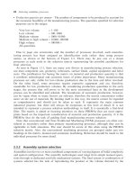
A process capability chart showing the achievable dimensional tolerances for hand/spray lay-up is
provided (see 2.8CC). Wall thickness tolerances are typically Æ0.5 mm.
2.8CC Contact molding process capability chart.
Contact molding 85
//SYS21///INTEGRAS/B&H/PRS/FINALS_07-05-03/0750654376-CH002-1.3D – 86 – [35–248/214] 9.5.2003 2:05PM
2.9 Continuous extrusion (plastics)
Process description
.
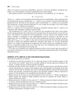
The raw material is fed from a hopper into a heated barrel and pushed along a screw-type feeder
where it is compressed and melts. The melt is then forced through a die of the required profile where
it cools on exiting the die (see 2.9F).
Materials
.
Most plastics, especially thermoplastics, but also some thermosets and elastomers.
.
Raw material in pellet, granular or powder form.
Process variations
.
Most extruders are equipped with a single screw, but two-screw or more extruders are available.
These are able to produce coaxial fibers or tubes and multi-component sheets.
.
Metal wire, strips and sections can be combined with the extrusion process using an offset die to
produce plastic coatings.
.
Pultrusion: for fiber-reinforced rods, tubes and sections.
Economic considerations
.
Production rates are high but are dependent on size. Continuous lengths up to 60 m/min for some
tube sections and profiles, up to 5 m/min for sheet and rod sections.
.
Extruders are often run below their maximum speed for trouble free production.
.
It can have multiple holes in die for increased production rates.
.
Extruder costs increase steeply at the higher range of output.
.
Lead times are dependent on the complexity of the 2-dimensional die, but normally weeks.
.
Material utilization is good. Waste is only produced when cutting continuous section to length.
.
Process flexibility is moderate. Tooling is dedicated, but changeover and setup times are short.
2.9F Continuous extrusion (plastics) process.
86 Selecting candidate processes
//SYS21///INTEGRAS/B&H/PRS/FINALS_07-05-03/0750654376-CH002-1.3D – 87 – [35–248/214] 9.5.2003 2:05PM
.
Production of 1000 kg of profile extrusion is economical, 5000 kg for sheet extrusions (equates to
about 10 000 items).
.
Tooling costs are generally moderate.
.
Equipment costs are high.
.
Some materials give off toxic or volatile gases during extrusion. Possible need for air extraction and
washing plant which adds to equipment cost.
.
Direct labor costs are low.
.
Finishing costs are low. Cutting to length only real cost.
Typical applications
.
Complex profiles. All types of thin walled, open or closed profiles
.
Rods, bar, tubing and sheet
.
Small diameter extruded bar which is cut into pellets and used for other plastic processing methods
.
Fibers for carpets, tyre reinforcement, clothes and ropes
.
Cling-film
.
Plastic pipe for plumbing
.
Plastic-coated wire, cable or strips for electrical applications
.
Window frames
.
Trim and sections for decorative work
Design aspects
.
Dedicated to long products with uniform cross-sections.
.
Cross-sections may be extremely intricate.
.
Solid forms including re-entrant angles, closed or open sections.
.
Section profile designed to increase assembly efficiency by integrating part consolidation features.
.
Grooves, holes and inserts not parallel to the axis of extrusion must be produced by secondary
operations.
.
No draft angle required.
.
Maximum section ¼ 150 mm.
.
Minimum section ¼ 0.4 mm for profiles (0.02 mm for sheet).
.
Sizes ranging 6 mm
2
–1800 mm wide sheet, and 11–1150 mm for tubes and rods.
Quality issues
.
The rate and uniformity of cooling are important for dimensional control because of shrinkage and
distortion.
.
Extrusion causes the alignment of molecules in solids.
.
Die swell, where the extruded product increases in size as it leaves the die, may be compensated for by:
.
Increasing haul-off rate compared with extrusion rate
.
Decreasing extrusion rate
.
Increasing the length of the die land
.
Decreasing the melt temperature.
.
There is a tendency for powdered materials to carry air into the extruder barrel: trapped gases have
a detrimental effect on both the output and the quality of the extrusion.
.
Surface roughness is good to excellent.
.
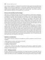
Process capability charts showing the achievable dimensional tolerances for various materials are
provided (see 2.9CC).
Continuous extrusion (plastics) 87
//SYS21///INTEGRAS/B&H/PRS/FINALS_07-05-03/0750654376-CH002-1.3D – 88 – [35–248/214] 9.5.2003 2:05PM
2.9CC Continuous extrusion (plastics) process capability chart.
88 Selecting candidate processes
//SYS21///INTEGRAS/B&H/PRS/FINALS_07-05-03/0750654376-CH002-1.3D – 89 – [35–248/214] 9.5.2003 2:05PM
3 Forming processes
//SYS21///INTEGRAS/B&H/PRS/FINALS_07-05-03/0750654376-CH002-1.3D – 90 – [35–248/214] 9.5.2003 2:05PM
3.1 Forging
Process description
.
Hot metal is formed into the required shape by the application of pressure or impact forces causing
plastic deformation using a press or hammer in a single or a series of dies (see 3.1F).
Materials
.
Mainly carbon, low alloy and stainless steels, aluminum, copper and magnesium alloys. Titanium
alloys, nickel alloys, high alloy steels and refractory metals can also be forged.
.
Forgeability of mater ials important; must be ductile at forging temperature. Relative forgeability is as
follows, with the easiest to forge first: aluminum alloys, magnesium alloys, copper alloys, c arbon steels,
low alloy steels, stainless steels, titanium alloys, high alloy steels, refractory metals and nickel alloys.
Process variations
.
Presses can be mechanical, hydraulic or drop hammer type.
.
Closed die forging: series of die impressions used to generate shape.
.
Open die forging: hot material deformed between a flat or shaped punch and die. Sections can be
flat, square, round or polygon. Shape and dimensions largely controlled by operator.
.
Roll forging: reduction of section thickness of a doughnut-shaped preform to increase its diameter.
Similar to ring rolling (see 3.2), but uses impact forces from hammers.
.
Upset forging: heated metal stock gripped by dies and end pressed into desired shape, i.e.
increasing the diameter by reducing height.
3.1F Forging process.
90 Selecting candidate processes
//SYS21///INTEGRAS/B&H/PRS/FINALS_07-05-03/0750654376-CH002-1.3D – 91 – [35–248/214] 9.5.2003 2:05PM
.
Hand forging: hot material reduced, upset and shaped using hand tools and an anvil. Commonly
associated with the blacksmith’s trade, used for decorative and architectural work.
.
Precision forging: near-net shape generation through the use of precision dies. Reduces waste and
minimizes or eliminates machining.
Economic considerations
.
Production rates from 1 to 300/h, depending on size.
.
Production most economic in the production of symmetrical rough forged blanks using flat dies.
Increased machining is justified by increased die life.
.
Lead times typically weeks.
.
Material utilization moderate (20–25 per cent scrap generated in flash typically).
.
Economically viable quantities greater than 10 000, but can be as low as 100 for large parts.
.
In the case of open die forging: lower material utilization, machining of the final shape necessary,
slow production rate, low lead times, commonly used for one-offs and high usage of skilled labor.
.
Tooling costs high.
.
Equipment costs generally high.
.
Direct labor costs moderate. Some skilled operations may be required.
.
Finishing costs moderate. Removal of flash, cleaning and fettling important for subsequent opera-
tions.
Typical applications
.
Engine components (connecting rods, crankshafts, camshafts)
.
Transmission components (gears, shafts, hubs, axles)
.
Aircraft components (landing gear, airframe parts)
.
Tool bodies
.
Levers
.
Upset forging: for bolt heads, valve stems
.
Open die forging: for die blocks, large shafts, pressure vessels
Design aspects
.
Complexity is limited by material flow through dies.
.
Deep holes with small diameters are better drilled.
.
Drill spots caused by die impressions can be used to aid drill centralization for subsequent machin-
ing operations.
.
Locating points for machining should be away from parting line due to die wear.
.
Markings are possible at little expense on adequate areas that are not to be subsequently
machined.
.
Care should be taken with design of die geometry, since cracking, mismatch, internal rupture and
irregular grain flow can occur.
.
It is good practice to have approximately equal volumes of material both above and below the
parting line.
.
Inserts and undercuts are not possible.
.
Placing of parting line is important, i.e. avoid placement across critical dimensions, keep along
simple plane, line of symmetry or follow the part profile.
.
Corner radii and fillets should be as large as possible to aid hot metal flow.
.
Maximum length to diameter ratio that can be upset is 3:1.
Forging 91
//SYS21///INTEGRAS/B&H/PRS/FINALS_07-05-03/0750654376-CH002-1.3D – 92 – [35–248/214] 9.5.2003 2:05PM
.
Avoid abrupt changes in section thickness. Causes stress concentrations on cooling.
.
Minimum corner radii ¼ 1.5 mm.
.
Machining allowances range from 0.8 to 6 mm, depending on size.
.
Drafts must be added to all surfaces perpendicular to the parting line.
.
Draft angles ranging 0–8
, depending on internal or external features, and section depth, but
typically 4
. Reduced by mechanical ejectors in dies.
.
Minimum section ¼ 3 mm.
.
Sizes ranging 10 g–250 kg in weight, but better for parts less than 20 kg.
Quality issues
.
Good strength, fatigue resistance and toughness in forged parts due to grain structure alignment
with die impression and principal stresses expected in service.
.
Low porosity, defects and voids encountered.
.
Forgeability of material important and maintenance of optimum forging temperature during proces-
sing.
.
Hot material in contact with the die too long will cause excessive wear, softening and breakage.
.
Variation in blank mass causes thickness variation. Reduced by allowing for flash generation, but
increases waste.
.
Residual stresses can be significant. Can be improved with heat treatment.
.
Die wear and mismatch may be significant.
.
Surface roughness and detail may be adequate, but secondary processing usually employed to
improve the surface properties.
.
Surface roughness ranging 1.6–25 mm Ra.
.
Process capability charts showing the achievable dimensional tolerances for closed die forging
using various materials are provided. Note, the total tolerance on Charts 1–4 is allocated þ2/3, À1/3.
Allowances of þ0.3–þ2.8 mm should be added for dimensions across the parting line and mismatch
tolerances ranging 0.3–2.4 mm, depending on part size (see 3.1CC).
.
Tolerances for open die forging ranging Æ2–Æ50 mm, depending on size of work and skill of the
operator.
92 Selecting candidate processes
//SYS21///INTEGRAS/B&H/PRS/FINALS_07-05-03/0750654376-CH002-1.3D – 93 – [35–248/214] 9.5.2003 2:05PM
3.1CC Forging process capability chart.
Forging 93
//SYS21///INTEGRAS/B&H/PRS/FINALS_07-05-03/0750654376-CH002-1.3D – 94 – [35–248/214] 9.5.2003 2:05PM
3.2 Rolling
Process description
.
Continuous forming of metal between a set of rotating rolls whose shape or height is adjusted
incrementally to produce desired section through imposing high pressures for plastic deformation. It
is the process of reducing thickness, increasing length without increasing the width markedly. Can
be performed with the material at a high temperature (hot) or initially at ambient temperature (cold)
(see 3.2F).
Materials
.
Most ductile metals such as low carbon, alloy and stainless steels, aluminum, copper and magne-
sium alloys.
.
Metal ingots called blooms, slabs or billets, used to load the mill. Blooms are used to produce
structural sections (beams, channels, rail sections), slabs are used to produce flat products such as
sheets and plate, and billets are rolled into rods and bars using shaped rolls.
.
Continuous casting also used for higher efficiency and lower cost.
Process variations
.
Variety of roll combinations exist (called mills):
.
Two high: commonly used for hot rolling of plate and flat product, either reversing or non-reversing
type.
.
Two high with vertical rolls: commonly used for hot rolling of structural sections. Vertical rolls
maintain uniform deformation of section and prevent cracking.
3.2F Rolling process.
94 Selecting candidate processes
//SYS21///INTEGRAS/B&H/PRS/FINALS_07-05-03/0750654376-CH002-1.3D – 95 – [35–248/214] 9.5.2003 2:05PM
.
Three high: for reversing one length above the other simultaneously.
.
Four high (tandem): backing rolls give more support to the rolls in contact with product for initial
reduction of ingots.
.
Cluster mills: very low roll deflection obtained due to many supporting rolls above the driven rolls
that are in contact with product. For cold rolling thin sheets and foil to close dimensional
tolerances.
.
Leveling rolls: used to improve flatness of strip product after main rolling operations.
.
Flat rolling: for long continuous lengths (long discontinuous lengths in reality) of flat product. The
height between the rolls is adjusted lower on each reversing cycle, or the product is passed through
a series of tandem rollers with decreasing roller gap and increasing speed, to reduce the product to
its final thickness. Tandem roll system has higher production rates.
.
Shape rolling: billet is passed through a series of shaped grooves on same roll or a set of rolls in
order to gradually form the final shape. Typically used for structural sections.
.
Transverse or cross rolling: wedge shaped forms in a pair of rolls create the final shape on short-
cropped bars in one revolution. For parts with axial symmetry such as spanners.
.
Ring rolling: an internal roller (idler) and external roller (driven) impart pressure on to the thickness of
a doughnut-shaped metal preform. As the thickness decreases, the diameter increases. For creat-
ing seamless rings used for pressure vessels, jet engine parts and bearing races. Rectangular cross
sections and contours are also possible. Can be readily automated.
.
Pack rolling: operation where two or more layers of metal are rolled together.
.
Thread rolling: wire or rod is passed between two flat plates, one moving and the other stationary,
with a thread form engraved on surfaces. Used to produce threaded fasteners with excellent
strength and surface integrity at high production rates and no waste.
.
Roll forming: forming of long lengths of sheet metal into complex profiles using a series of rolls
(see 3.9).
.
Calandering: thermoplastic raw material is passed between a series of heated rollers in order to
produce sheet product.
Economic considerations
.
Production rates high. Continuous process with speeds ranging 20–500 m/min.
.
Production rates for related processes: transverse rolling up to 100/h and thread rolling up to
30 000/h.
.
Lead times typically months due to number of mills required and complexity of profile.
.
Long set-up times for shaped rolls.
.
Hot rolling requires less energy than cold rolling.
.
Material utilization very good (rolling is a constant volume process). Less than 1 per cent scrap
generated, commonly through line stoppages or when cutting to lengths. Can be recycled.
.
High degree of automation possible.
.
Plane rolls flexible in the range of flat products they can produce. Shaped rolls dedicated and
therefore not flexible
.
Economical for very high production runs. Minimum quantity 50 000 m of rolled product (equivalent
to 100 000þ ).
.
Tooling costs high.
.
Equipment costs high.
.
Direct labor costs low to moderate.
.
Finishing costs very low.
Rolling 95
//SYS21///INTEGRAS/B&H/PRS/FINALS_07-05-03/0750654376-CH002-1.3D – 96 – [35–248/214] 9.5.2003 2:05PM
Typical applications
.
Rolling is an important process for producing the stock material for many other processes, e.g.
machining, cold forming and sheet metal work. Around 90 per cent of all stock product used is
produced by rolling for many industries:
.
Flat, square, rectangular and polygon sections
.
Structural sections, e.g. I-beams, H-beams, T-sections, channels, rails, angles and plate
.
Strip, foil and sheet
.
Sheet for shipbuilding
.
Structural fabrication
.
Sheet metal for shearing and forming operations
.
Tube forming
.
Automotive trim
Design aspects
.
Simple shapes using flat rolling, fairly complex 2-dimensional profiles using shape rolling and
3-dimensional shapes for transverse rolling.
.
Re-entrant angles possible on profile.
.
No draft angles required, except in transverse rolling.
.
Hot rolling:
Minimum section ¼ 1.6 mm.
Maximum section ¼ 1m.
.
Cold rolling:
Minimum section ¼ 0.0025 mm.
Maximum section ¼ 200 mm.
.
Maximum width ¼ 5m.
Quality issues
.
Coarse grain structure and porosity of hot ingot or continuous casting is gradually improved and
finer grain structure produced with little or no voids.
.
Hot rolling takes place above recrystallization temperature, and therefore sections are free from
residual stresses. No working hardening of material.
.
Anisotropy in cold-rolled sections are due to directionality of grains during rolling and work hard-
ening. Can be used to advantage, but does mean high compressive residual stresses that exist in
surface are balanced by high tensile residual stresses in section bulk. Can lead to surface delami-
nation.
.
High sulfur contents in steels can cause cracking and flaring of rolled section ends. Possibility of
jamming when introduced to a subsequent set of rolls. High scrap rates and downtime can be
experienced if this occurs.
.
Hot-rolled material is more difficult to handle than cold rolled. Cold-rolled strip product can be coiled
for subsequent processing, hot rolled cannot.
.
Rough surface finish of rolls is used in hot rolling to aid traction of metal through the rolls. Cold rolling
rolls have a high surface finish.
.
Lubrication can be used for ferrous alloys (graphite) and non-ferrous alloys (oil emulsion) to
minimize friction during rolling.
.
Cold rolling can be performed with low viscosity lubricants such as paraffin or oil emulsion.
96 Selecting candidate processes
//SYS21///INTEGRAS/B&H/PRS/FINALS_07-05-03/0750654376-CH002-1.3D – 97 – [35–248/214] 9.5.2003 2:05PM
.
Hot rolling requires the preparation of stock material to remove surface oxides before processing.
.
Maintenance of rolling temperature dictates quality. Too low and becomes difficult to deform. Too
high and surface quality is reduced.
.
Roll material must be highly wear resistant. Made to withstand 5 000 000 m of rolled section
production. Can be re-coated and ground back to size.
.
Surface defects may result from inclusions and impurities in the material (scale, rust, dirt, roll marks,
and other causes related to prior treatment of ingots).
.
Surface detail is poor in hot-rolled product (oxide layer called mill scale is always present). Oxide
layer can be removed by pickling in acid.
.
Surface detail is excellent for cold rolling.
.
Surface roughness values ranging 6.3–50 mmRaforhotrolling,0.2–6.3mm Ra for cold rolling.
.
Process capability charts showing the achievable dimensional tolerances for cold rolling various
materials are provided (see 3.2CC).
.
Achievable tolerances ranging Æ1–Æ2.5 per cent of the dimension for hot rolling. Dimensional
variations are greater than cold rolling due to non-uniformities in material properties such as
hardness, roll deflection and surface conditions.
Rolling 97
//SYS21///INTEGRAS/B&H/PRS/FINALS_07-05-03/0750654376-CH002-1.3D – 98 – [35–248/214] 9.5.2003 2:05PM
3.2CC Rolling process capability chart.
98 Selecting candidate processes
//SYS21///INTEGRAS/B&H/PRS/FINALS_07-05-03/0750654376-CH002-1.3D – 99 – [35–248/214] 9.5.2003 2:05PM
3.3 Drawing
Process description
.
A number of processes where long lengths of rod, tube or wire are pulled through dies to progres-
sively reduce the original cross-section through plastic deformation. The process is performed cold
(see 3.3F).
Materials
.
Any ductile metal at ambient temperatures.
Process variations
.
Rod or bar drawing: reduction of the diameter of rod or bar through a single die or progressive
reduction through a number of dies.
.
Wire drawing: performed on multiple wire drawing machine where the wire is wrapped around blocks
before being pulled through the next die to successively reduce diameter. Wire diameters that
cannot be wrapped around blocks are drawn out on long benches at low speeds, but give lower
production rates.
.
Tube drawing: reduction of either the diameter of a tube or simultaneous reduction of diameter and
thickness using mandrel.
.
Can use rollers in place of dies for plastic deformation.
.
Sizing is a low deformation operation sometimes used to finish the drawn section giving closer
dimensional accuracy and surface roughness.
3.3F Drawing process.
Drawing 99
//SYS21///INTEGRAS/B&H/PRS/FINALS_07-05-03/0750654376-CH002-1.3D – 100 – [35–248/214] 9.5.2003 2:05PM
Economic considerations
.
Production rates from 10 (rod, tube) to 2000 m/min (wire).
.
Lead time typically days.
.
Material utilization excellent. Some scrap may be generated when cutting to length.
.
High degree of automation possible.
.
Economical for high production runs (1000 mþ ).
.
Tooling costs low.
.
Equipment costs moderate.
.
Direct labor costs low to moderate.
.
Finishing costs very low. Cutting long lengths of rod, bar and tube to length only.
Typical applications
.
Drawing is an important process for producing the stock material for many other processes, e.g.
machining and cold heading.
.
Rod, bar, wire, tubes
.
Fabrication and machine construction
.
Spring wire, musical instrument wire
Design aspects
.
Simple shapes with rotational symmetry only.
.
No draft angles required.
.
Rod drawing:
Minimum diameter ¼ 10.1 mm.
Maximum diameter ¼ 150 mm.
.
Wire drawing:
Minimum diameter ¼ 10.1 mm.
Maximum diameter ¼ 120 mm.
.
Tube drawing:
Minimum diameter ¼ 16 mm.
Maximum diameter ¼ 1600 mm.
Minimum section ¼ 0.1 mm.
Maximum section ¼ 25 mm.
Quality issues
.
Strain hardening occurs in material during cold working, giving high strength.
.
High directionality (anisotropy) due to nature of plastic deformation and grain orientation in direction
of drawing.
.
High friction between work and die causes high temperatures which must be reduced through
external cooling.
.
Surface detail excellent.
.
Surface roughness ranging 0.2–6.3 mm Ra.
.
Finer surface roughness values obtained with finer grit grades.
.
Process capability charts showing the achievable dimensional tolerances for cold drawing various
materials are provided (see 3.3CC).
100 Selecting candidate processes
//SYS21///INTEGRAS/B&H/PRS/FINALS_07-05-03/0750654376-CH002-1.3D – 101 – [35–248/214] 9.5.2003 2:05PM
3.3CC Drawing process capability chart.
Drawing 101
//SYS21///INTEGRAS/B&H/PRS/FINALS_07-05-03/0750654376-CH002-1.3D – 102 – [35–248/214] 9.5.2003 2:05PM
3.4 Cold forming
Process description
.
Various processes under the heading of cold forming tend to combine forward and backward
extrusion to produce near-net shaped components by the application of high pressures and forces
(see 3.4F).
Materials
.
Any ductile material at ambient temperature, including: aluminum, copper, zinc, lead and tin alloys,
and low carbon steels. Also alloy and stainless steels, nickel and titanium alloys processed on a
more limited basis.
Process variations
.
Impact extrusion: similar to cold extrusion, but cold billet is plastically deformed by a single blow of
the tool. Can be forward or backward extrusion (Hooker process).
.
Cold forming: can be forward, backward or a combination of both.
.
Hydrostatic extrusion: metal forced through die by high fluid pressure. Used for high strength, brittle
and refractory alloys.
.
Can incorporate other processes such as: cold heading, drawing, swaging, sizing and coining to
produce complex parts at one station.
3.4F Cold forming process.
102 Selecting candidate processes
//SYS21///INTEGRAS/B&H/PRS/FINALS_07-05-03/0750654376-CH002-1.3D – 103 – [35–248/214] 9.5.2003 2:05PM
Economic considerations
.
Production rates up to 2000/h.
.
Lead times usually weeks.
.
High utilization of material (95 per cent). Possible material cost savings over machining can be high.
Near elimination of heat treatment and machining requirements.
.
Can be economical for quantities down to 10 000, depending on complexity of part. More suited for
high production volumes (100 000þ ).
.
Most applications in the formation of symmetrical parts with solid or hollow cross sections.
.
Tooling costs high.
.
Equipment costs high.
.
Direct labor costs low.
.
Finishing costs very low.
Typical applications
.
Fasteners
.
Tool sockets
.
Spark plug bodies
.
Gear blanks
.
Collapsible tubes
.
Valve seats
Design aspects
.
Complexity limited. Symmetry of the part is important: concentric, round or square cross-sections
typical. Limited asymmetry possible.
.
To avoid mismatch of dies, every effort should be made to balance the forces, especially on
unsymmetrical parts.
.
Length to diameter ratios of secondary formed back-extruded parts may approach 10:1; forward
extrusion unlimited.
.
Any parting lines should be kept in one plane and placement across critical dimensions should be
avoided.
.
Can be used to process two materials simultaneously to produce parts such as steel-coated copper
electrodes.
.
Inserts not recommended.
.
Undercuts not possible.
.
Draft angles not required.
.
Maximum section ranging 0.25–22 mm, depending on material for impact extrusion. No limit for cold
forming.
.
Minimum section ranging 0.09–0.25 mm, depending on material.
.
Sizes ranging 11.3–1150 mm, depending on cold formability of material being processed.
Quality issues
.
Inside shoulders require secondary processing to ensure flatness.
.
Cold working offers valuable increase in mechanical properties, including extended fatigue life.
.
Concentricity of blank and punch is important in providing uniform section thickness.
Cold forming 103