Process Selection - From Design to Manufacture Episode 1 Part 5 pot
Bạn đang xem bản rút gọn của tài liệu. Xem và tải ngay bản đầy đủ của tài liệu tại đây (555.13 KB, 20 trang )
//SYS21///INTEGRAS/B&H/PRS/FINALS_07-05-03/0750654376-CH002-1.3D – 64 – [35–248/214] 9.5.2003 2:05PM
2.1 Injection molding
Process description
.
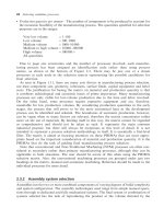
Granules of polymer material are heated and then forced under pressure using a screw into the die
cavity. On cooling, a rigid part or tree of parts is produced (see 2.1F).
Materials
.
Mostly thermoplastics, but thermosets, composites and elastomers can be processed.
Process variations
.
Injection blow molding: allows small hollow parts with intricate neck detail to be produced.
.
Co-injection: for products with rigid cores pre-placed in the die before injection or simultaneous
injection of different materials into same die.
Economic considerations
.
Production rates are high, 1–50/min, depending on size.
.
Thermoset parts usually have a longer cycle time.
.
Lead times can be several weeks due to manufacturing of complex dies.
.
Material utilization is good. Scrap generated in sprues and risers.
.
If material permits, gates and runners can be reused resulting in lower material losses.
.
Flexibility limited by dedicated dies, die changeover and machine setup times.
.
Economical for high production runs, typically 10 000þ.
.
Full automation achievable. Robot machine loading and unloading common.
2.1F Injection molding process.
64 Selecting candidate processes
//SYS21///INTEGRAS/B&H/PRS/FINALS_07-05-03/0750654376-CH002-1.3D – 65 – [35–248/214] 9.5.2003 2:05PM
.
Tooling costs are very high. Dies are usually made from hardened tool steel.
.
Equipment costs are very high.
.
Direct labor costs are low to moderate.
.
Finishing costs are low. Trimming is required to remove gates and runners.
Typical applications
.
High precision, complex components
.
Automotive and aerospace components
.
Electrical parts
.
Fittings
.
Containers
.
Cups
.
Bottle tops
.
Housings
.
Tool handles
Design aspects
.
Very complex shapes and intricate detail possible.
.
Holes, inserts, threads, lettering, color, bosses and minor undercuts possible.
.
Uniform section thickness should be maintained.
.
Unsuitable for the production of narrow necked containers.
.
Variation in thickness should not exceed 2:1.
.
Marked section changes should be tapered sufficiently.
.
Living hinges and snap features allow part consolidation.
.
Placing of parting line important, i.e. avoid placement across critical dimensions.
.
The clamping force required proportional to the projected area of the molded part.
.
Radii should be as generous as possible. Minimum inside radii ¼ 1.5 mm.
.
Draft angle ranging from less than 0.25 to 4
, depending on section depth.
.
Maximum section, typically ¼ 13 mm.
.
Minimum section ¼ 0.4 mm for thermoplastics, 0.9 mm for thermosets.
.
Sizes ranging 10 g–25 kg in weight for thermoplastics, 6 kg maximum for thermosets.
Quality issues
.
Thick sections can be problematic.
.
Care must be taken in the design of the running and gating system, where multiple cavities used to
ensure complete die fill.
.
Control of material and mold temperature critical, also injection pressure and speed, condition of
resin, dwell and cooling times.
.
Adequate clamping force necessary to prevent the mold creating flash.
.
Thermoplastic molded parts usually require n o de-fl ashing: thermoset parts often r equire this operation.
.
Excellent surface detail obtainable.
.
Surface roughness a function of the die condition. Typically, 0.2–0.8 mm Ra is obtainable.
.
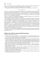
Process capability charts showing the achievable dimensional tolerances using various materials are
provided (see 2.1CC). Allowances of approximately Æ0.1 mm should be added for dimensions across
the parti ng line. Note, that cha rts 1, 2 and 3 are to be used for components t hat have a major di mension,
greater than 50 mm, and typically large production volumes. The chart titled ‘Light Engineering’ is used
for components with a major dimension, less than 150 mm, and for small production volumes.
Injection molding 65
//SYS21///INTEGRAS/B&H/PRS/FINALS_07-05-03/0750654376-CH002-1.3D – 66 – [35–248/214] 9.5.2003 2:05PM
2.1CC Injection molding capability chart.
66 Selecting candidate processes
//SYS21///INTEGRAS/B&H/PRS/FINALS_07-05-03/0750654376-CH002-1.3D – 67 – [35–248/214] 9.5.2003 2:05PM
2.2 Reaction injection molding
Process description
.
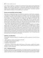
Two components of a thermosetting resin are injected into a mixing chamber and then injected into
the mold at high speed where polymerization and subsequent solidification takes place (see 2.2F).
Materials
.
Mostly thermosets.
.
Foamed materials possessing a solid skin can be created by setting up a pressure differential
between mixing chamber and mold.
.
Can add chopped fiber material (glass, carbon) for added stiffness to mixing to produce composites.
Process variations
.
Mold material is usually aluminum. Can also use resin for low production runs or hardened tool steel
for very high volumes.
.
Further heating of resin components before mixing is dependent on material used.
Economic considerations
.
Production rates from 1 to 10/h.
.
Lead times can be several weeks.
.
Material utilization good. Less than 1 per cent lost in scrap.
.
Scrap cannot be recycled.
2.2F Reaction injection molding process.
Reaction injection molding 67
//SYS21///INTEGRAS/B&H/PRS/FINALS_07-05-03/0750654376-CH002-1.3D – 68 – [35–248/214] 9.5.2003 2:05PM
.
Flexibility limited by dedicated dies, die changeover and machine setup times.
.
Economical for low to medium production volumes (10–10 000).
.
Can be used for one-offs, e.g. prototyping.
.
Tooling costs low.
.
Equipment costs high.
.
Direct labor costs moderate to high.
.
Finishing costs low. A little trimming required.
Typical applications
.
Car bumpers
.
Cups
.
Containers
.
Panels
.
Housings
.
Footwear
.
Garden furniture
Design aspects
.
Very complex shapes and intricate detail possible.
.
Ribs, holes, bosses and inserts possible.
.
Small re-entrant features possible.
.
Radii should be as generous as possible.
.
Uniform section thickness should be maintained.
.
Marked section changes should be tapered sufficiently.
.
Placing of parting line important, i.e. avoid placement across critical dimensions.
.
Draft angles ranging 0.5–3
, depending on section depth.
.
Maximum section ¼ 10 mm.
.
Minimum section ¼ 1.5 mm; foamed material ¼ 3 mm.
.
Maximum dimension ¼ 1.5 m.
.
Sizes ranging 100 g–10 kg in weight.
Quality issues
.
Thick sections can be problematic.
.
Care must be taken in the design of the running and gating system, where multiple cavities are used
to ensure complete die fill.
.
Problems can be created by premature reaction before complete filling of mold.
.
Excellent surface detail is obtainable.
.
Surface roughness is variable, but mainly dependent on mold finish.
.
Achievable dimensional tolerances are approximately Æ0.05 at 25 mm, Æ0.3 at 150 mm. Allowances
of approximately Æ0.2 mm should be added for dimensions across the parting line.
68 Selecting candidate processes
//SYS21///INTEGRAS/B&H/PRS/FINALS_07-05-03/0750654376-CH002-1.3D – 69 – [35–248/214] 9.5.2003 2:05PM
2.3 Compression molding
Process description
.
A measured quantity of raw, unpolymerized plastic material is introduced into a heated mold which
is subsequently closed under pressure, forcing the material into all areas of the cavity as it melts.
Analogous to closed die forging of metals (see 2.3F).
Materials
.
Mainly thermosets, but also some composites, elastomers and a limited number of thermoplastics.
.
Raw material supplied in either powder or liquid resin form.
Process variations
.
Flash-type: for shallow parts, but more material lost.
.
Semi-positive (partly positive, partly flash): used for closer tolerance work or when the design
involves marked changes in section thickness.
.
Positive: high density parts involving composite Sheet Molding Compounds (SMC), Bulk Molding
Compounds (BMC) or impact-thermosetting materials.
.
Cold-molding: powder or filler is mixed with a binder, compressed in a cold die and cured in an oven.
Strictly for thermosets.
Economic considerations
.
Production rates are from 20 to 140/h.
.
Cycle time is restricted by material handling. Each cavity must be loaded individually.
.
The greater the thickness of the part, the longer the curing time.
2.3F Compression molding process.
Compression molding 69
//SYS21///INTEGRAS/B&H/PRS/FINALS_07-05-03/0750654376-CH002-1.3D – 70 – [35–248/214] 9.5.2003 2:05PM
.
Multiple cavity mold increases production rate.
.
Mold maintenance is minimal.
.
Certain amount of automation is possible.
.
Time required for polymerization (curing) depends mainly on the largest cross section of the product
and the type of molding compound.
.
Lead times may be several weeks according to die complexity.
.
Material utilization is high. No sprues or runners.
.
Flexibility is low. Differences in shrinkage properties reduces the capability to change from one
material to another.
.
Production volumes are typically 1000þ, but can be as low as 100 for large parts.
.
Tooling costs are moderate to high.
.
Equipment costs are moderate.
.
Direct labor costs are low to moderate.
.
Finishing costs are generally low. Flash removal required.
Typical applications
.
Dishes
.
Housings
.
Automotive parts
.
Panels
.
Handles
.
Container caps
.
Electrical components and fittings
Design aspects
.
Shape complexity limited to relatively simple forms. Molding in one plane only.
.
Threads, ribs, inserts, lettering, holes and bosses possible.
.
When molding materials with reinforcing fibers, directionality maintained enabling high strength to
be achieved.
.
Thin-walled parts with minimum warping and dimensional deviation may be molded.
.
Placing of parting line important, i.e. avoid placement across critical dimensions.
.
A draft angle of greater than 1
required.
.
Maximum section, typically ¼ 13 mm.
.
Minimum section ¼ 0.8 mm.
.
Maximum dimension, typically ¼ 450 mm.
.
Minimum area ¼ 3mm
2
.
.
Maximum area ¼ 1.5 m
2
.
.
Sizes ranging from several grams to 16 kg in weight.
Quality issues
.
Variation in raw material charge weight results in variation of part thickness and scrap.
.
Air entrapment is possible.
.
Internal stresses are minimal.
.
Dimensions in the direction of the mold opening and the product density will tend to vary more than
those perpendicular to the mold opening.
.
Flash molds do not require that the quantity of material is controlled.
70 Selecting candidate processes
//SYS21///INTEGRAS/B&H/PRS/FINALS_07-05-03/0750654376-CH002-1.3D – 71 – [35–248/214] 9.5.2003 2:05PM
.
Tumbling may be required as a finishing process to remove flash.
.
Surface detail is good.
.
Surface roughness is a function of the die condition. Typically, 0.8 mm Ra is obtained.
.
Process capability charts showing the achievable dimensional tolerances using various materials
are provided (see 2.3CC). Allowances of approximately Æ0.1 mm should be added for dimensions
across the parting line.
2.3CC Compression molding process capability chart.
Compression molding 71
//SYS21///INTEGRAS/B&H/PRS/FINALS_07-05-03/0750654376-CH002-1.3D – 72 – [35–248/214] 9.5.2003 2:05PM
2.4 Transfer molding
Process description
.
A heated mold is closed under low pressure and then a liquid resin and catalyst is loaded into an
adjacent mixing head and forced via a plunger into the cavity where curing takes place. Full name is
resin transfer molding (see 2.4F).
Materials
.
Limited to only several thermosetting plastics and elastomers, with or without fillers.
.
Can use pre-pressed fiber-packs to fit the mold, called preforms. Fibers can be glass or carbon.
Process variations
.
Powder material placed in a heated melting pot and forced under pressure into a heated mold.
.
Vacuum assisted resin injection: additional vacuum can be used in mold cavity to assist resin filling
of fiber preforms.
Economic considerations
.
Production rates 20–300/h. Fast curing speed.
.
Lead time typically days, depending on complexity of tool.
.
Material utilization very good. Less than 3 per cent scrap typically.
.
Scrap material cannot be recycled directly.
.
High degree of automation possible.
2.4F Transfer molding process.
72 Selecting candidate processes
//SYS21///INTEGRAS/B&H/PRS/FINALS_07-05-03/0750654376-CH002-1.3D – 73 – [35–248/214] 9.5.2003 2:05PM
.
Economical for production runs of 1000–10 000.
.
Tooling costs moderate to high.
.
Equipment costs generally moderate.
.
Direct labor costs low to moderate.
.
Some skilled labor required, but easily reduced with automation.
.
Finishing costs low, but no opportunity for in-mold trimming.
Typical applications
.
Electrical cabinets
.
Housings and panels
.
Car body panels
.
Wind turbine blades
.
Seating
.
Yacht hulls and decks
.
Plant growing trays
.
Garden ponds
Design aspects
.
Complex geometries possible and hollow shapes.
.
Cores possible for increased complexity.
.
Can mold around inserts and delicate cores easily.
.
Lettering, ribs, holes, inserts and threads possible.
.
Undercuts possible, but at added cost.
.
Thickness variation less than 2:1.
.
Draft angles ranging 2–3
preferred, but can be as low as 0.5
.
.
Minimum inside radius ¼ 6 mm.
.
Minimum section ranging 0.8–1.5 mm, depending on material used.
.
Maximum section ¼ 90 mm.
.
Maximum dimension ¼ 450 mm.
.
Minimum area ¼ 3mm
2
.
.
Maximum size 16 kg in weight, but suited to smaller parts.
Quality issues
.
Differential stress distribution may occur due to flow characteristics of mold resulting in minor
distortion.
.
High temperatures above resin melting temperatures must be maintained prior and during mold
filling.
.
Improperly placed fiber preforms can cause dry spots or pools of resin on surface of finished part.
.
Fiber preforms can also move during injection mold filling without proper fixing arrangements within
mold.
.
Variation in resin/fiber concentration is difficult to control in sharp corners.
.
It is not recommended for parts subjected to high loads in service.
.
Surface detail is excellent.
.
Surface roughness is a function of the die condition, with 0.8 mm Ra, readily obtainable.
.
Achievable dimensional tolerances are Æ0.05 at 25 mm, Æ0.15 at 150 mm. Wall thickness
tolerances are typically Æ0.25 mm.
Transfer molding 73
//SYS21///INTEGRAS/B&H/PRS/FINALS_07-05-03/0750654376-CH002-1.3D – 74 – [35–248/214] 9.5.2003 2:05PM
2.5 Vacuum forming
Process description
.
A plastic sheet is softened by heating elements and pulled under vacuum on to the surface form of a
cold mold and allowed to cool. The part is then removed (see 2.5F).
Materials
.
Several thermoplastics that can be produced in sheet form.
.
The material to be processed should exhibit high uniform elongation.
.
Can also introduce some fiber reinforcing material to improve strength and rigidity.
Process variations
.
Molds are usually made of cast aluminum or aluminum filled epoxy.
.
Sheets can be heated by infrared heaters or in ovens.
.
Can have top and bottom heating elements, or top heating element only.
.
For thick sheets, a top enclosure and compressed air is used.
.
Sheet is drawn over mold with additional force, other than provided by the vacuum, until cooled.
.
Thermoforming: for thin-walled parts such as packaging.
Economic considerations
.
Production rates from 60 to 360/h commonly. Cups can be produced at 3600/h.
.
Lead times of a few days typically.
2.5F Vacuum forming process.
74 Selecting candidate processes
//SYS21///INTEGRAS/B&H/PRS/FINALS_07-05-03/0750654376-CH002-1.3D – 75 – [35–248/214] 9.5.2003 2:05PM
.
Material utilization moderate to low. Unformed parts of the sheet are lost and cannot be directly
recycled.
.
Full automation achievable.
.
Multiple molds may be used.
.
Setup times and changeover times low.
.
Sheet material much more expensive than raw pellet material.
.
Production volumes economical in small batches of 10–1000.
.
Tooling costs low to moderate, depending on complexity.
.
Equipment costs low to moderate, but can be high if automated.
.
Labor costs low to moderate.
.
Finishing costs low. Some trimming of unformed material after molding.
Typical applications
.
Open plastic containers and panels
.
Pages of Braille text
.
Vending cups
.
Food packaging and containers
.
Automotive parts
.
Electrical cabinets and enclosures
.
Bath tubs, sink units and shower panels
.
Dinghy hulls
.
Signs
Design aspects
.
Shape complexity limited to moldings in one plane.
.
Open forms of constant thickness.
.
Undercuts possible with a split mold.
.
Cannot produce parts with large surface areas.
.
Bosses, ribs and lettering possible, but at large added cost.
.
Parts with molded-in holes not possible.
.
Corner radii should be large compared to thickness of material.
.
Sharp corners should be avoided.
.
No parting lines.
.
Draft angles of 1
or greater recommended.
.
Maximum section ¼ 3 mm.
.
Minimum section ¼ 0.05–0.5 mm, depending on material used.
.
Sizes ranging from 25 mm
2
to 2.5 Â 7.5 m in area.
Quality issues
.
Control of temperature, clamping force and vacuum pressure important if variability is to be minimized.
.
Thermoplastic material must possess a high uniform elongation otherwise tearing at critical points in
the mold may occur.
.
Sheet material will have a plastic memory and so at high temperatures the formed part will revert
back to original sheet profile. Operating temperature therefore important.
.
Uniform temperature control of sheet important.
Vacuum forming 75
//SYS21///INTEGRAS/B&H/PRS/FINALS_07-05-03/0750654376-CH002-1.3D – 76 – [35–248/214] 9.5.2003 2:05PM
.
If multiple molds used it is necessary that there is sufficient distance between cavities to avoid flow
interference.
.
Excessive thinning can occur, particularly at sharp corners.
.
Surface detail fair.
.
Surface finish good and related to the condition of mold surface.
.
Achievable tolerances ranging Æ0.25–Æ2 mm, and largely mold dependent. Wall thickness toler-
ances typically Æ20 per cent of the nominal.
76 Selecting candidate processes
//SYS21///INTEGRAS/B&H/PRS/FINALS_07-05-03/0750654376-CH002-1.3D – 77 – [35–248/214] 9.5.2003 2:05PM
2.6 Blow molding
Process description
.
A hot hollow tube of plastic, called a parison, is extruded or injection molded downwards and then
caught between two halves of a shaped mold which closes the top and bottom of the parison. Hot air
is blown into the parison, expanding it until it uniformly contacts the inside contours of the cold mold.
The part is allowed to cool and is then ejected (see 2.6F).
Materials
.
Most thermoplastics.
Process variations
.
Extrusion blow molding: more applicable to asymmetrical parts, integrated handles possible.
.
Injection blow molding: parison injection molded and then transferred to blow molding machine. For
small parts with intricate neck detail.
.
Multiple parisons: can create multi-layered parts. This requires close control since uneven parisons
produce waste.
.
Parisonless blowing: similar to dip-coating followed by expansion into the mold.
.
Stretch blow molding: the simultaneous axial and radial expansion of a parison, yielding a biaxially
orientated container.
Economic considerations
.
Production rates between 100 and 2500/h, depending on size.
.
Lead times a few days.
2.6F Blow molding process.
Blow molding 77
//SYS21///INTEGRAS/B&H/PRS/FINALS_07-05-03/0750654376-CH002-1.3D – 78 – [35–248/214] 9.5.2003 2:05PM
.
Integration with extrusion process to produce parison provides continuous operation.
.
There is generally little material waste, but can increase with some complex geometries using
extrusion blow molding.
.
Full automation readily achievable.
.
Flexibility limited since molds are dedicated.
.
Setup times and changeover times relatively short.
.
Production volumes of 1000, but better suited to very high volumes.
.
Tooling costs moderate to high.
.
Equipment costs moderate to high, especially for full automation.
.
Direct labor costs low. One operator can manage several machines.
.
Finishing costs low. Some trimming required.
Typical applications
.
Hollow plastic parts with relatively thin walls
.
Bottles
.
Bumpers
.
Ducting
Design aspects
.
Complexity limited to hollow, well rounded, thin walled parts with low degree of asymmetry.
.
Asymmetrical moldings, e.g. off-set necks possible with movable blowing spigots.
.
Undercuts, bosses, ribs, lettering, inserts and threads possible.
.
Corner radii should be as generous as possible (>3 mm).
.
Placing of parting line important, i.e. avoid placement across critical dimensions.
.
Holes cannot be molded-in.
.
Draft angles not required.
.
Maximum section ¼ 6 mm. Thick sections may need cooling aids (carbon dioxide or nitrogen gas).
.
Minimum section ¼ 0.25 mm.
.
Sizes ranging 12 mm in length to volumes up to 3 m
3
.
Quality issues
.
Poor control of wall thickness, typically Æ50 per cent of nominal.
.
Creep and chemical stability of product important considerations.
.
Residual stresses, e.g. non-uniform deformation, may relax in time causing distortion of the part.
.
Good surface detail and finish possible.
.
The higher the pressure the better the surface finish of the product.
.
A process capability chart showing the achievable dimensional tolerances is provided (see 2.6CC).
Allowances of approximately Æ0.1 mm should be added for dimensions across the parting line.
78 Selecting candidate processes
//SYS21///INTEGRAS/B&H/PRS/FINALS_07-05-03/0750654376-CH002-1.3D – 79 – [35–248/214] 9.5.2003 2:05PM
2.6CC Blow molding process capability chart.
Blow molding 79
//SYS21///INTEGRAS/B&H/PRS/FINALS_07-05-03/0750654376-CH002-1.3D – 80 – [35–248/214] 9.5.2003 2:05PM
2.7 Rotational molding
Process description
.
Raw material is placed in the mold and simultaneously heated and rotated forcing the particles to
deform and melt on the walls of a female mold without the application of external pressure or
centrifugal forces. The part is cooled whilst rotating. The mold is designed to rotate about two
perpendicular axes (see 2.7F).
Materials
.
Several common thermoplastics, including difficult fluoropolymers.
.
Raw material supplied as finely ground powder.
Process variations
.
Slush molding: uses liquid polymers (plastisols) for small hollow parts.
.
Air, water or mist can be used for mold cooling.
Economic considerations
.
Production rates of 3–50/h, but dependent on size.
.
To increase production rates, three-arm carousels often used with one mold each in the load-
unload, heat and cool positions.
.
Lead time several days.
.
Material utilization very high. Little waste material.
.
Production volumes in the range of 100–1000 typically.
2.7F Rotational molding process.
80 Selecting candidate processes
//SYS21///INTEGRAS/B&H/PRS/FINALS_07-05-03/0750654376-CH002-1.3D – 81 – [35–248/214] 9.5.2003 2:05PM
.
Tooling costs low.
.
Equipment costs low to moderate.
.
Labor costs moderate.
.
Finishing costs low. Little finishing required.
Typical applications
.
Water tanks
.
Storage vessels
.
Dust bins
.
Buckets
.
Housings
.
Drums
.
Prototypes
Design aspects
.
Complexity limited to large, hollow parts of uniform wall thickness.
.
Long, thin projections not possible.
.
Large flat surfaces should be avoided due to distortion and difficulty to form. Use stiffening ribs.
.
Internal walls need to be well spaced.
.
Molded-in holes, bosses, finishes and lettering all possible at added cost and limited accuracy.
.
With rotation speed variation, can build up thicker layers at key points in the mold.
.
Integral handles possible.
.
Large threads can be molded-in.
.
Undercuts should be avoided.
.
Sharp corners difficult to fill in the mold. Radii should be as generous as possible (greater than five
times the wall thickness) and tend to become thicker than the wall thickness on molding.
.
Metal or higher-melting point plastic inserts can be molded-in.
.
Can clad the inside of the finished part using another polymer.
.
Placing of parting line important, i.e. avoid placement across critical dimensions.
.
Holes cannot be molded although open-ended articles possible.
.
Thickness variation should be less than 2:1.
.
Draft angles generally greater than 1
, typically 3
.
.
Maximum section ¼ 13 mm.
.
Minimum section typically 2 mm, but can be as low as 0.5 mm for certain applications.
.
Sizes up to 4 m
3
.
Quality issues
.
The part is practically free from residual stresses.
.
Surface detail is fair.
.
Outer surface finish of the part is a replica of the inside finish of the mold walls.
.
Control of inside surface finish is not possible.
.
Wall thickness is determined by the close control of the amount of raw material used.
.
Dimensional variations can be large if sufficient setting time is not allowed before removal of the part.
.
A process capability chart showing the achievable dimensional tolerances is provided (see 2.7CC).
Allowances of approximately Æ0.5 mm should be added for dimensions across the parting line.
.
Wall thickness tolerances are generally between Æ5 and Æ20 per cent of the nominal.
Rotational molding 81
//SYS21///INTEGRAS/B&H/PRS/FINALS_07-05-03/0750654376-CH002-1.3D – 82 – [35–248/214] 9.5.2003 2:05PM
2.7CC Rotational molding process capability chart.
82 Selecting candidate processes
//SYS21///INTEGRAS/B&H/PRS/FINALS_07-05-03/0750654376-CH002-1.3D – 83 – [35–248/214] 9.5.2003 2:05PM
2.8 Contact molding
Process description
.
Glass fiber reinforced material (30–45 per cent by volume) and a liquid thermosetting resin are
simultaneously formed into a male or female mold and cured at room temperature or with the
application of heat to accelerate the process (see 2.8F).
Materials
.
Glass reinforced fiber in woven, continuous and chopped roving, mat and cloth forms.
.
Can use pre-impregnated sheets of uncured resin and fiber, called SMC.
.
Thermosetting liquid resin: commonly catalyzed polyester or epoxy.
Process variations
.
Hand lay-up: manual laying of fiber reinforced material and application of resin to mold to build up
the thickness. Hand or roller pressure removes any trapped air.
.
Variations on hand lay-up are:
.
Vacuum bag molding: uses a rubber bag clamped over the mold. A vacuum is applied between
the mold and the bag to squeeze the resin/reinforcement together removing any trapped air.
Curing performed in an oven.
.
Pressure bag molding: as vacuum bag molding, but pressure is applied above the bag. Can be
used for thicker section parts.
.
Hand lay-up using SMC: cured by heat and clamped if necessary to further reduce air pockets.
2.8F Contact molding process.
Contact molding 83