Process Selection - From Design to Manufacture Episode 1 Part 4 doc
Bạn đang xem bản rút gọn của tài liệu. Xem và tải ngay bản đầy đủ của tài liệu tại đây (550.51 KB, 20 trang )
//SYS21///INTEGRAS/B&H/PRS/FINALS_07-05-03/0750654376-CH002-1.3D – 44 – [35–248/214] 9.5.2003 2:05PM
1.3CC Gravity die casting process capability chart.
44 Selecting candidate processes
//SYS21///INTEGRAS/B&H/PRS/FINALS_07-05-03/0750654376-CH002-1.3D – 45 – [35–248/214] 9.5.2003 2:05PM
1.4 Pressure die casting
Process description
.
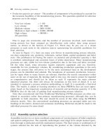
Molten metal is inserted into a metallic mold under very high pressures (100þ bar), where it
solidifies. The die is then opened and the casting ejected (see 1.4F).
Materials
.
Limited to non-ferrous metals, i.e. zinc, aluminum, magnesium, lead, tin and copper alloys.
.
Zinc and aluminum alloys tend to be the most popular materials.
.
High-temperature metals, such as copper alloys, reduce die life.
.
Iron-based materials for casting are under development.
Process variations
.
Dies and cores are made from hardened and tempered alloy steel.
.
Cold-chamber die casting: shot cylinder filled with a ladle for each cycle. Used for high melting
temperature metals.
.
Hot-chamber die casting: shot cylinder immersed in molten metal and then forced using a separate
ram. Used for low melting temperature metals due to erosive nature of molten metal. Can be either
plunger or goose-neck type.
.
Vacuum die casting: overcomes porosity for larger castings.
.
Injection metal assembly: variant of hot-chamber die casting for the assembly of parts such as tubes
and plates, cable terminations and to act as rivets by injecting zinc or lead alloys into a cavity in the
assembly.
1.4F Pressure die process.
Pressure die casting 45
//SYS21///INTEGRAS/B&H/PRS/FINALS_07-05-03/0750654376-CH002-1.3D – 46 – [35–248/214] 9.5.2003 2:05PM
Economic considerations
.
Very high production rates possible, up to 200/h.
.
Lead time very long, months possibly.
.
Material utilization high.
.
Gates, sprues, etc., can be re-melted.
.
High initial die costs due to high complexity and difficulty to manufacture.
.
Full automation achievable. Robot machine loading and unloading common.
.
Production quantities of up to 10 000 economically viable for copper alloys, but 100 000þ for
aluminum, zinc and lead alloys.
.
Tooling costs very high.
.
Equipment costs very high.
.
Direct labor costs low.
.
Finishing costs low. Trimming operations are required to remove flash, gates and sprues.
Typical applications
.
Transmission cases
.
Machine and engine parts
.
Pump components
.
Electrical boxes
.
Domestic appliance components
.
Toy bodies
.
Pump and impeller parts
Design aspects
.
Shape complexity can be high. Limited by design of movable cores.
.
Bosses, large threads, undercuts and inserts all possible with added cost.
.
Molded-in bearing shells possible.
.
Lettering possible.
.
Wall thickness should be as uniform as possible; transitions should be gradual.
.
Sharp corners should be avoided, but pressure die casting permits smaller radii, because metal flow
is aided.
.
Placing of parting line important, i.e. avoid placement across critical dimensions.
.
Holes perpendicular to the parting line can be cast.
.
Casting holes for subsequent tapping generally more economical than drilling.
.
Cored holes greater than 10.8 mm.
.
Machining allowance normally in the range 0.25–0.8 mm.
.
Draft angle ranging 0.25–3
, depending on section depth.
.
Maximum section ¼ 13 mm.
.
Minimum section ranging 0.4 mm for zinc alloys, 1.5 mm for copper alloys.
.
Sizes ranging 10 g–50 kg. Castings up to 100 kg made in zinc. Copper, tin and lead castings
normally less than 5 kg.
Quality issues
.
Low porosity in small castings typically, but can be a problem in castings with thick or long sections.
.
Particularly suited where casting requires high mechanical properties or absence of creep.
46 Selecting candidate processes
//SYS21///INTEGRAS/B&H/PRS/FINALS_07-05-03/0750654376-CH002-1.3D – 47 – [35–248/214] 9.5.2003 2:05PM
.
The high melting temperature of some metals can cause significant processing difficulties and die wear.
.
Ejector pins may leave small marks and should be positioned at points of strength on the casting.
.
Process variables need to be controlled. Variation in temperature, pressure and cycle time espe-
cially important for consistency.
.
Difficulty is experienced in obtaining sound castings in the larger capacities due to gas entrapment.
.
Close control of temperature, pressure and cooling times important in obtaining consistent quality
castings.
.
Mechanical properties are fair, but poorer than some other casting methods.
.
Surface detail excellent.
.
Surface roughness ranging 0.4–3.2 mm Ra.
.
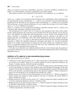
Process capability charts showing the achievable dimensional tolerances using various materials
are provided (see 1.4CC). Allowances of Æ0.05–Æ0.35 mm should be added for dimensions across
the parting line.
1.4CC Pressure die casting process capability chart.
Pressure die casting 47
//SYS21///INTEGRAS/B&H/PRS/FINALS_07-05-03/0750654376-CH002-1.3D – 48 – [35–248/214] 9.5.2003 2:05PM
1.5 Centrifugal casting
Process description
.
Molten metal is poured into a high-speed rotating mold (300–3000 rpm depending on diameter) until
solidification takes place. The axis of rotation is usually horizontal, but may be vertical for short work
pieces (see 1.5F).
Materials
.
Most metals suitable for static casting are suitable for centrifugal casting: all steels, iron, copper,
aluminum and nickel alloys.
.
Also, glass, thermoplastics, composites and ceramics (metal molds sprayed with a refractory
material) can be molded by this method.
Process variations
.
Semi-permanent or expendable molds.
.
Semi-centrifugal casting: used to cast parts with radial symmetry in a vertical axis of rotation at low
speeds.
.
Centrifuge casting: a number of molds are arranged radially around a central sprue. Molten metal is
poured into the sprue and is forced into the mold cavities by centrifugal force due to high-speed
rotation. Used for small gears mainly and parts of intricate detail.
Economic considerations
.
Production rates of up to 50/h possible, but dependent on size.
.
Lead time may be several weeks.
1.5F Centrifugal casting process.
48 Selecting candidate processes
//SYS21///INTEGRAS/B&H/PRS/FINALS_07-05-03/0750654376-CH002-1.3D – 49 – [35–248/214] 9.5.2003 2:05PM
.
Material utilization high (90–100 per cent). No runners or risers.
.
Economic when the mechanical properties of thick-walled tubes are important and high alloy grades
of steel are required.
.
In large quantities, production of other than circular external shapes becomes more economical.
.
Small diameter steel tubes made by this method not competitive with welded or rolled tubes.
.
Selection of mold type (permanent or sand) determined by shape of casting, quality and number to
be produced.
.
Production volumes low, typically 100þ. Can be used for one-offs.
.
Tooling costs moderate.
.
Equipment costs low to moderate.
.
Direct labor costs low to moderate.
.
Finishing costs low to moderate. Normally, machining of internal dimension necessary.
Typical applications
.
Pipes
.
Brake drums
.
Pulley wheels
.
Train wheels
.
Flywheels
.
Gun barrels
.
Gear blanks
.
Large bearing liners
.
Engine-cylinder liners
.
Pressure vessels
.
Nozzles
Design aspects
.
Shape complexity limited by nature of process, i.e. suited to parts with rotational symmetry.
.
Contoured surfaces possible.
.
Circular bore remains in the finished part.
.
Dual metal tubes that combine the properties of two metals in one application possible.
.
Inserts and bosses possible, but undercuts are not.
.
Placing of parting line important, i.e. avoid placement across critical dimensions.
.
Cored holes greater than 125 mm.
.
Machining allowances ranging 0.75–6 mm.
.
Draft angle approximately 1
.
.
Maximum section thickness approximately 125 mm.
.
Minimum section ranging 2.5–8 mm, depending on material cast.
.
Maximum length ¼15 m.
.
Sizes ranging 125 mm–12m.
.
Sizes up to 5 t in weight have been cast.
Quality issues
.
Properties of castings vary by distance from the axis of rotation.
.
Due to density differences in the molten material, dross, impurities and pieces of the refractory lining
tend to collect on the inner surface of the casting. This is usually machined away.
Centrifugal casting 49
//SYS21///INTEGRAS/B&H/PRS/FINALS_07-05-03/0750654376-CH002-1.3D – 50 – [35–248/214] 9.5.2003 2:05PM
.
Tubular castings have higher structural strengths and more distinct cast impressions than gravity die
cast or sand cast parts.
.
Castings are free of shrinkage due to one-directional cooling.
.
The mechanical properties of dense castings are comparable with that of forgings. Fine grain
castings and low porosity is an advantage.
.
Good mechanical properties and fine grain structure.
.
Surface detail is fair to good.
.
Surface roughness ranging 1.6–12.5 mm Ra.
.
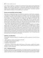
A process capability chart showing the achievable dimensional tolerances is provided (see 1.5CC).
Allowances of approximately Æ0.25–Æ0.75 mm should be added for dimensions across the parting
line. Note, the chart applies to outside dimensions only. Internal dimensions are approximately
50 per cent greater.
1.5CC Centrifugal casting process capability chart.
50 Selecting candidate processes
//SYS21///INTEGRAS/B&H/PRS/FINALS_07-05-03/0750654376-CH002-1.3D – 51 – [35–248/214] 9.5.2003 2:05PM
1.6 Investment casting
Process description
.
A mold is used to generate a wax pattern of the shape required. A refractory material zircon, then
a ceramic slurry and finally a binder is used to coat the pattern which is slow fired in an oven to cure.
The wax is melted out and the metal cast in the ceramic mold. The mold is then destroyed to remove
the casting. Process often known as the ‘Lost Wax’ process (see 1.6F).
Materials
.
All metals, including precious, refractory and reactive alloys (cast in vacuum).
Process variations
.
Blends of resin, filler and wax used.
.
Use of thermoplastic resin instead of wax.
.
Ceramic and water soluble cores can be used.
Economic considerations
.
Production rates of up to 1000/h, depending on size.
.
Lead times usually several weeks, but can be shorter.
.
Slow process due to many steps in production. Cure time can be as high as 48 h.
.
Wax or plastic patterns can be injection molded for high production volumes.
.
Best suited to metals having high melting temperatures, and/or which difficult to machine or which
have high cost.
1.6F Investment casting process.
Investment casting 51
//SYS21///INTEGRAS/B&H/PRS/FINALS_07-05-03/0750654376-CH002-1.3D – 52 – [35–248/214] 9.5.2003 2:05PM
.
Material utilization high.
.
Some automation possible.
.
Pattern costs can be high for low quantities.
.
Ceramic and wax cores allow complex internal configurations to be produced, but increase the cost
significantly.
.
A ‘tree’ of wax patterns enables many small castings to be handled together.
.
Most suitable for small batches (10–1000) using manual labor, but also high-volume production
with automation.
.
Sometimes used for one-offs, especially in decorative work.
.
Tooling costs low to moderate, but dependent on complexity.
.
Equipment costs low to moderate (high when processing reactive materials).
.
Labor costs very high. Can be labor intensive as many operations involved.
.
Finishing costs low to moderate. Gates and feeders are removed by machining or grinding. As cast
part typically cleaned by shot, bead or sand blasting.
Typical applications
.
Turbine blades
.
Machine tool parts
.
Aerospace components
.
Valve and pump casings
.
Pipe fittings
.
Automotive engine components
.
Decorative work, e.g. figurines
.
Optical instrument parts
.
Small arms parts
.
Gear blanks
.
Levers
.
Jewelry
Design aspects
.
Very complex castings with unusual internal configurations possible.
.
Wax pattern must be easily removable from its mold.
.
Complex shapes assembled from several simpler shapes.
.
Practical way of producing threads in hard to machine materials, or where thread design unusual.
.
Uniform sections preferred. Abrupt changes should be gradually blended in or designed out.
.
Avoid sharp corners.
.
Fillets should be as generous as possible.
.
Bosses and undercuts possible with added cost.
.
Inserts not possible, but integral rivets are.
.
Lettering possible, either in relief or inset.
.
Molded-in holes, both blind and through possible, but difficult.
.
Length to diameter ratio for blind holes typically 4:1.
.
Minimum hole ¼ 10.5 mm.
.
Machining allowance usually between 0.25 mm and 0.75 mm, depending on size.
.
Draft angle usually zero, but 0.5–1
desirable on long extended surfaces, or if mold cavity is deep.
.
Minimum section ranging from 1 mm for aluminum alloys and steels, 2 mm for copper alloys, but can
be as low as 0.6 mm for some applications.
.
Maximum section ¼ 75 mm.
52 Selecting candidate processes
//SYS21///INTEGRAS/B&H/PRS/FINALS_07-05-03/0750654376-CH002-1.3D – 53 – [35–248/214] 9.5.2003 2:05PM
.
Maximum dimension ¼ 1m.
.
Sizes ranging 0.5 g–100 kg in weight, but best for parts less than 5 kg.
Quality issues
.
Moderate porosity.
.
High strength castings can be produced.
.
Grain growth more pronounced in longer sections which may limit the toughness and fatigue life of
the part.
.
Quality of casting to a large degree dependent upon the characteristics of wax.
.
Very good to excellent surface detail possible.
.
Surface roughness ranging 0.4–6.3 mm Ra.
.
Flatness tolerances typically Æ0.13 mm per 25 mm, but dependent on surface area.
.
Minimum angular tolerance ¼Æ0.5
.
.
A process capability chart showing the achievable dimensional tolerances is provided (see 1.6CC).
.
No parting line on casting.
1.6CC Investment casting process capability chart.
Investment casting 53
//SYS21///INTEGRAS/B&H/PRS/FINALS_07-05-03/0750654376-CH002-1.3D – 54 – [35–248/214] 9.5.2003 2:05PM
1.7 Ceramic mold casting
Process description
.
A precision pattern generates the mold which is coated with a ceramic slurry. The mold is dried and
baked. The molten metal is then poured into the mold and allowed to solidify. The mold is broken to
remove the part (see 1.7F).
Materials
.
All metals, but to a lesser degree, aluminum, magnesium, zinc, tin and copper alloys.
Process variations
.
Variations on the composition of the ceramic slurry and curing mechanism.
.
Plaster, wood, metal or rubber are used for patterns.
Economic considerations
.
Production rates of up to 10/h typical.
.
Lead times can be several days.
.
Material utilization high.
.
Low scrap losses.
.
Best suited to metals having high melting temperatures and/or that are difficult to machine.
.
Can be combined with investment casting to produce parts with increased complexity with reduced
cost.
1.7F Ceramic mold casting process.
54 Selecting candidate processes
//SYS21///INTEGRAS/B&H/PRS/FINALS_07-05-03/0750654376-CH002-1.3D – 55 – [35–248/214] 9.5.2003 2:05PM
.
Suitable for small batches and medium-volume production.
.
Can be used for one-offs.
.
Tooling costs moderate.
.
Equipment costs moderate to high.
.
Direct labor costs moderate to high.
.
Finishing costs low. Usually no machining is required.
Typical applications
.
All types of dies and molds for other casting and forming processes
.
Cutting tool blanks
.
Components for food handling machines
.
Pump impellers
.
Aerospace and atomic reactor components
Design aspects
.
High complexity possible – almost any shape possible.
.
Use of cores increases complexity obtainable.
.
Inserts, bosses and undercuts possible.
.
Placing of parting line important, i.e. avoid placement across critical dimensions.
.
Cored holes greater than 10.5 mm.
.
Where machining required, allowances of up to 0.6 mm should be observed.
.
Draft angle usually zero, but 0.1–1
preferred.
.
Minimum section ranging 0.6–1.2 mm, depending on material used.
.
Sizes ranging 100 g–3 t in weight, but less than 50 kg better.
Quality issues
.
Low porosity.
.
Mechanical properties are good.
.
Good surface detail possible.
.
Surface roughness ranging 0.8–6.3 mm Ra.
.
A process capability chart showing the achievable dimensional tolerances is provided (see 1.7CC).
An allowance of Æ0.25 mm should be added for dimensions across the parting line.
.
Parting lines sometimes pronounced on finished casting.
Ceramic mold casting 55
//SYS21///INTEGRAS/B&H/PRS/FINALS_07-05-03/0750654376-CH002-1.3D – 56 – [35–248/214] 9.5.2003 2:05PM
1.7CC Ceramic mold casting process capability chart.
56 Selecting candidate processes
//SYS21///INTEGRAS/B&H/PRS/FINALS_07-05-03/0750654376-CH002-1.3D – 57 – [35–248/214] 9.5.2003 2:05PM
1.8 Plaster mold casting
Process description
.
A precision metal pattern (usually brass) generates the two part mold which is made of a gypsum
slurry material. The mold is removed from the pattern and baked to remove the moisture. The molten
metal is poured into the mold and allowed to cool. The mold is broken to remove the part (see 1.8F).
Materials
.
Limited to low melting temperature metals, i.e. aluminum, copper, zinc and magnesium alloys due to
degradation of the plaster mold at elevated temperatures.
.
Tin and lead alloys are sometimes processed.
Process variations
.
Patterns can be made from: metal, plaster, wood or thermosetting plastic. Wood has a limited life
due to water absorption from the plaster slurry.
.
Composition of plaster slurry varies. Additives are sometimes used to control mold expansion and
fibers added to improve mold strength.
Economic considerations
.
Production rates of up to 10/h typical.
.
Lead times can be several days to weeks.
.
Material utilization high.
.
Low scrap losses. Waste recycled.
1.8F Plaster mold casting process.
Plaster mold casting 57
//SYS21///INTEGRAS/B&H/PRS/FINALS_07-05-03/0750654376-CH002-1.3D – 58 – [35–248/214] 9.5.2003 2:05PM
.
Mold destroyed in removing casting.
.
Easy to change design during production.
.
Suitable for small batches of 100 and medium-volume production.
.
Tooling costs low to moderate.
.
Equipment costs moderate.
.
Direct labor costs moderate to high. Some skilled operations necessary.
.
Finishing costs low. Little finishing required except grinding for gate removal and sanding of parting
line.
Typical applications
.
Pump impellers
.
Waveguide components (for use in microwave applications)
.
Lock components
.
Gear blanks
.
Valve parts
.
Molds for plastic and rubber processing, i.e. tyre molds
Design aspects
.
Moderate to high complexity possible.
.
Possible to make mold from several pieces.
.
Deep holes not recommended.
.
Sharp corners and features can be cast easily.
.
Bosses and undercuts possible with little added cost.
.
Placing of parting line important, i.e. avoid placement across critical dimensions.
.
Cored holes greater than 113 mm.
.
Where machining required, allowances of up to 0.8 mm should be observed.
.
Draft angles ranging 0.5–2
preferred, but can be zero.
.
Minimum section ranging 0.8–1.8 mm, depending on material used.
.
Sizes ranging 25 g–50 kg in weight. However, castings up to 100 kg have been made.
Quality issues
.
Little or no distortion on thin sections.
.
Plaster mold has low permeability and can create gas evolution problems.
.
Moderate to high porosity obtained.
.
Mechanical properties fair.
.
Surface detail good.
.
Surface roughness ranging 0.8–3.2 mm Ra.
.
A process capability chart showing the achievable dimensional tolerances is provided (see 1.8CC).
An allowance of approximately Æ0.25 mm should be added for dimensions across the parting line.
58 Selecting candidate processes
//SYS21///INTEGRAS/B&H/PRS/FINALS_07-05-03/0750654376-CH002-1.3D – 59 – [35–248/214] 9.5.2003 2:05PM
1.8CC Plaster mold casting process capability chart.
Plaster mold casting 59
//SYS21///INTEGRAS/B&H/PRS/FINALS_07-05-03/0750654376-CH002-1.3D – 60 – [35–248/214] 9.5.2003 2:05PM
1.9 Squeeze casting
Process description
.
Combination of casting and forging. Molten metal fills a preheated mold from the bottom and during
solidification the top half of the mold applies a high pressure to compress the material into the final
desired shape. Also known as liquid metal forging and load pressure casting (see 1.9F).
Materials
.
Typically non-ferrous metals, but occasionally ferrous alloys.
Process variations
.
Pouring can be performed automatically.
Economic considerations
.
Production rates low due to mold filling for minimum turbulence.
.
Long setup times.
.
Lead time moderate to high.
.
Material utilization excellent. Near-net shape achieved.
.
High degree of automation possible.
.
Economically viable for production volumes of 10 000þ.
.
Tooling costs high.
.
Equipment costs high.
1.9F Squeeze casting process.
60 Selecting candidate processes
//SYS21///INTEGRAS/B&H/PRS/FINALS_07-05-03/0750654376-CH002-1.3D – 61 – [35–248/214] 9.5.2003 2:05PM
.
Direct labor costs low to moderate.
.
Finishing costs very low. Used to minimize or eliminate secondary processing.
Typical applications
.
Aerospace components
.
Suspension parts
.
Steering elements
.
Brake components
Design aspects
.
Complex geometries possible.
.
Retractable and disposable cores used to create complex internal features.
.
Large variations in cross section possible.
.
Undercuts, bosses, holes and inserts possible.
.
Placing of parting line important, i.e. avoid placement across critical dimensions.
.
Machining allowances usually in the range 0.6–1.2 mm.
.
Draft angle ranging 0.1–3
, depending on section depth.
.
Maximum section ¼ 200 mm.
.
Minimum section ¼ 6 mm.
.
Minimum dimension ¼ 120 mm.
.
Sizes ranging 25 g–4.5 kg in weight.
Quality issues
.
Low porosity experienced.
.
Low speed mold filling minimizes splashing.
.
Accurate metering of molten metal required to flashing.
.
Excellent mechanical properties can be obtained, similar to forging.
.
Adequate process control important, i.e. metering of molten metal, pressures, solidification
times, etc.
.
Graphite releasing agent and ejector pins commonly used to aid removal of finished part.
.
Surface detail good.
.
Surface roughness ranging 1.6–12.5 mm Ra.
.
Achievable dimensional tolerances approximately Æ0.15 at 25 mm, Æ0.3 at 150 mm. Allowances
of Æ0.25 mm should be added for dimensions across the parting line.
Squeeze casting 61
//SYS21///INTEGRAS/B&H/PRS/FINALS_07-05-03/0750654376-CH002-1.3D – 62 – [35–248/214] 9.5.2003 2:05PM
//SYS21///INTEGRAS/B&H/PRS/FINALS_07-05-03/0750654376-CH002-1.3D – 63 – [35–248/214] 9.5.2003 2:05PM
2 Plastic and composite
processing