Process Selection - From Design to Manufacture Episode 1 Part 3 ppsx
Bạn đang xem bản rút gọn của tài liệu. Xem và tải ngay bản đầy đủ của tài liệu tại đây (704.96 KB, 20 trang )
//SYS21///INTEGRAS/B&H/PRS/FINALS_07-05-03/0750654376-CH002.3D – 24 – [19–34/16] 13.5.2003 7:43PM
.
Production quantity per annum – The number of components to be produced to account for
the economic feasibility of the manufacturing process. The quantities specified for selection
purposes are in the ranges:
Very low volume ¼ 1–100
Low volume ¼ 100–1000
Medium volume ¼ 1000–10 000
Medium to high volume ¼ 10 000–100 000
High volume ¼ 100 000 þ
All quantities.
Due to page size constraints and the number of processes involved, each manufac-
turing process has been assigned an identification code rather than using process
names, as shown at the bottom of Figure 2.2. There may be just one or a dozen
processes at each node in the selection matrix representing the possible candidates for
final s electi on.
As seen in Figure 1.11, there are many cost drivers in manufacturing process selection,
not least component size, geometry, tolerances, surface finish, capital equipment and labor
costs. The justification for basing the matrix on material and production quantity is that
it combines technological and economic issues of prime importance. Many manufacturing
processes are only viable for low-volume production due to the time and labor involved.
On the other hand, some processes require expensive equipment and are, therefore,
unsuitable for low production volumes. By considering production quantities in the early
stages, the process that will prove to be the most economical later in the development
process can be identified and selected. The boundaries of economic production, however,
can be vague when so many factors are relevant, therefore the matrix concentrates rather
more on the use of materials. By limiting itself in this way, the matrix cannot be regarded
as comprehensive and should not be taken as such. It represents the main common
industrial practice, but there will always be exceptions at this level of detail. It is not
intended to represent a process selection methodology in itself. It is essentially a first-level
filter. The matrix is aimed at focusing attention on those PRIMAs that are most appro-
priate based on the important consideration of material and prod uction quantity. It is the
PRIMAs that do the task of guiding final manufacturing process selection.
Note that conventional and Non-Traditional Machining (NTM) processes are often con-
sidered as secondary rather than primary manufacturing processes, although they can be
applicable to both situations. The user should be aware of this when using the PRIMA
selection matrix. Also, the conventional machining processes are grouped under just two
headings in the matrix, manual and automatic machining. Reference should be made to the
individual processes for more detail.
2.3.2 Assembly system selection
Assemblies involve two or more combined components of varying degrees of build complexity
and spatial configuration. The assembly technologies used range from simple manual opera-
tions through to dedicated and fully mechanized systems. The final system or combination of
systems selected has the task of reproducing the product at the volume dictated by the
24 Selecting candidate processes
//SYS21///INTEGRAS/B&H/PRS/FINALS_07-05-03/0750654376-CH002.3D – 25 – [19–34/16] 13.5.2003 7:43PM
customer, in a cost-effective way for the producer, being technically appropriate for the
components manipulated and composed, and ultimately satisfying the functional require-
ments dictated by the specification.
The assembly phase represents a significant proportion of the total production cost of a
product and can outweigh manufacturing costs in some industries (2.3). Through the identi-
fication of the most effective manufacturing and assembly technologies early in the development
process, downstream activity, inefficiency and costs can be reduced. Significantly, assembly
is a major source of late engineering change, rework and production variability in product
development (2.4). The cost of recovering from these problems during assembly is high and is
estimated to be in the range of 5–10 per cent of the final cost (2.5). In part, this is due to the
fact that assembly is governed by much less controllable and less tangible issues than manu-
facturing, such as assembly actions and fixture design (2.6).
In practice, assembly selection is a very difficult task. It does not mean, however, that we
cannot make a sound decision about the most appropriate assembly technology to use for a
given set of conditions or requirements. A number of researchers have proposed strategies for
assembly system selection. The reader interested in this topic can find more information in
References (2.7–2.9).
Prior to the selection of an assembly technology, a number of activities should be under-
taken and factors considered, some of which also help drive the final quality of the assembly:
.
Business level – Identification and availability of assembly technologies/expertise in-house,
integration into business practices/strategy, geographical location and future competitive
issues, such as investment in equipment.
.
Product level – Anticipated lead times, product life, investment return time-scale, product
families/variants and product volumes required.
.
Supplier level – Com ponent quality (process capability, gross defects) and timely supply of
bought-in an d in-house manufactured parts.
The final point is of particular importance. A substantial proportion of a finished product,
typically, two-thirds, consists of components or s ub-assemblies produced by suppliers (2.10).
The original equipment manufacturer is fast becoming purely an assembler of these bought-in
parts, and therefore it is important to realize the key role suppliers have in developing products
that are also ‘assembly friendly’. Consideration must be given to the tolerances and process
variability associated with component parts from a very early stage, especially when using
automated assembly technologies, because production variability is detrimental to an assembly
process.
From the above, a number of drivers for assembly technology selection can be highlighted:
.
Availability of labor
.
Operating costs
.
Production quantity
.
Capital cost of assembly equipment
.
Production rate required
.
Number of components in the assembly
.
Number of product variants
.
Handling characteristics (safety, environmental hazards, supply logistics)
.
Complexity of components and assembly operations
.
Size and weight of components to be assembled.
PRIMA selection strategies 25
//SYS21///INTEGRAS/B&H/PRS/FINALS_07-05-03/0750654376-CH002.3D – 26 – [19–34/16] 13.5.2003 7:43PM
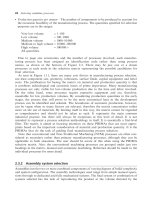
Figure 2.3 maps several of the important selection drivers with assembly technology. It is a
general guide for the selection of the most appropriate assembly system based on:
.
Number of product variants (flexibi lity), and
.
Production rate, or
.
Production quantity per annum,or
.
Capital cost of the assembly equipment (although this is more of an outcome than a requirement).
Three basic assembly systems can be identified and are classified in Figure 1.14 and with their
respective PRIMA number below:
.
Manual (with or without mechanized assistance) [6.1]
.
Flexible (programmable, robots) [6.2]
.
Dedicated (special purpose) [6.3].
Upon candidate selection, further reference is made to the individual PRIMAs for each
assembly system type in order to fully understand the technical and economic implications of
the final decision and explore system variants available. This is pa rticularly advantageous
when Figure 2.3 shows that a set of requirements is on the boundary of two assembly system
types.
Fig. 2.3 Assembly system selection chart.
26 Selecting candidate processes
//SYS21///INTEGRAS/B&H/PRS/FINALS_07-05-03/0750654376-CH002.3D – 27 – [19–34/16] 13.5.2003 7:43PM
2.3.3 Joining process selection
There is extensive evidence to suggest that many industrial products are designed with far too
many parts. DFA case studies indicate that in many designs large proportions of excess
components are only used for fastening (2.11). These non-value added components increase
part-count and production costs without contributing to the product’s functionality. In many
cases, inco rrect joining processes are used due to a lack of knowledge of such factors as
availability, cost and functional performance of alternatives. As with primary and secondary
manufacturing processes, selecting the most suitable joining process greatly influences
the manufacturability of a design, but the selection of the joining technology to be used can
also greatly influence the assemblability of a design. The method chosen can also have
a significant influence on the product architecture and assembly sequence and it is well
known that complicated joining processes lead to incorrect, incomplete an d faulty assemblies
(2.12).
Selecting the most appropriate joining technique requires consideration of many factors
relating to joint design, material properties and service conditions. During the selection
procedure the designer is required to scrutinize large quantities of data relating to many
different technologies. Several selection methods exist for the selection of the process variants
within individual joining technologies. However, selecting the most appropriate technology
itself remains a design-orientated task that often does not get the attention it deserves. It can
be concluded that a selection methodology that incorporates joining processes and tech-
nologies that can be applied at an early stage in the design process is a useful tool to support
designing and particularly DFA. Considering joining processes prior to the development of
detailed geometry enables components to be tailored to the selected process rather than
limiting the number of suitable processes. Addressing such issues during the early stages of
product development actively encourages designers to employ good DFA practice an d reduces
the need for costly redesign work.
As mentioned above, a number of other selection methods exist for different joining
technologies, and the reader interested in further information is referred to:
.
Adhesive bonding (2.13)(2.14)
.
Welding, soldering and brazing (1.6 )(1.7)(2.15)
.
All joining technologies (1.10)(2.16).
Currently, available selection techniques tend to focus on particular joining technologies or
do not offer the designer a wide range of suitable joining processes or in enough detail to
support the selection process. The aim of the joining process selection methodology pre-
sented here is to provide a means of identifying feasible methods of joining regardless of
their fundamental technology. The methodology is not intended to selec t a specific joining
method, for example, torch brazing or tubular rivet, but to highlight candidate processes
that are capable of joining under the given conditions. The final selection can be made
after considering process specific data and detailed data against design requirements from
the PRIMAs.
Joining process classification
Due to the large number of different joining processes and variants, only the most
commonly used and well-established processes in industry are included. Investigations
PRIMA selection strategies 27
//SYS21///INTEGRAS/B&H/PRS/FINALS_07-05-03/0750654376-CH002.3D – 28 – [19–34/16] 13.5.2003 7:43PM
highlighted 73 major joining techniques, as shown in Figure 1.15. In order to classify them,
a common factor is used, based on technology and process. Technology class refers to the
collective group that a process belongs to, for example, welding or adhesive bonding. The
process class refers to the specific joining technique, for example, Metal Inert-gas Welding
(MIG) or anaerobi c adhesive. Each process is derived from a particular fundamental
technology providing a means for classification. From this, the joining processes have been
divided into five main categories: welding, brazing, soldering, mechanical fastening and
adhesive bonding.
Technical classes can be separated into sub-categori es based on distinct differences in
underlying technology. Although the basic premise of all welding processes is the same,
specific techniques differ considerably due to the particular processes involved in generating
heat and/or enabling the fusion process. This can be used as a means of classifying sub-
sets. Both brazing and soldering have a number of different processes, hence they have
been split into two sub-sets. Mechanical fasteners can be divided in two ways, by group
technologies and degree of permanence. The latter has been chosen as it relates to the
functionality of the fastener in service and therefore product requirements. Due to the large
number of specific adhesives, which in many cases are exclusive to the producer, adhesive
bonding has been viewed from a generic level, therefore, only the adhesive group can be
selected.
Joining process selection criteria
In order to select the most appropriate joining process, it is necessary to consider all processes
available within the methodology. As technology specific selection criteria tend to be non-
transportable between domains, evaluating the merits of joining processes that are based on
fundamentally dissimilar technologies requires a different approach. Differentiating between
technology classes and process classes requires the comparison of specifically selected
parameters. In order to evaluate a joint , consideration must be given to its functional,
technical, spatial and economic requirements. A review of important joining requirements
has identified a number of possible selection criteria, as shown in Figure 2.4 and discussed
below.
.
Functional – Functional requirements define the working characteristics of the joint. The
functional considerations for a joint are degree of permanence, load type and strength.
Degree of permanence identifies whether a joint needs to be dismantled or not. In most
cases the permanence of a joining process is independent of its technology class. Degree
of permanence provides a suitable high-level selection criterion that is not reliant on
detailed geometry. Load type and strength are often mutually dependent and can
be influenced by the geometric characteristics of the joint interface. As joint design
is dissimilar for different technology classes, it is difficult to use load type or
strength as a universal selection criteria. However, these considerations must be
taken into account when evaluating suitable joining processes for final selection when
appropriate.
.
Technical – Specific needs of components to be joined are categorized by the joint’s technical
requirements. The technical considerations for a joint are material type, joint design and
operating temperature. Material type is selected based on parameters defined by the
28 Selecting candidate processes
//SYS21///INTEGRAS/B&H/PRS/FINALS_07-05-03/0750654376-CH002.3D – 29 – [19–34/16] 13.5.2003 7:43PM
product’s operating environment such as corrosion resistance. The material type is relevant
to all joining technologies because they need to be compatible. Jo int design is often defined
by the geometry. However, if joining is considered prior to detailed geometry, the selected
process can influence the design. Due to the fundamental differences in joint configurations,
it is not suitable as a selection criterion for non-technology specific selection. Operating
temperature influences the performance of most joining processes, although it should be
considered during material selection. While an important aspect, its effect varies for differ-
ent joining technologies. Therefore, consideration of operating temperature is more appro-
priate during final selection.
.
Spatial – Geometric characteristics of the joint are accounted for by the spatial require-
ments. The spatial requirements identified are size, weight, geometry and material thickness.
The size and weight of components to be joined is considered and determined when their
material is selected. As the selection methodology is intended for use prior to the develop-
ment of detailed geometry, using geometry as a selection criterion would be contradictory.
Material thickness has already proven to be a successful criterion in other selection
methodologies, and the suitability of joining processes is easily classified for different
thicknesses of material.
.
Economic – The economics of joining processes aligns the design with the business needs
of the product. Economic considerations can be split into two sections: tooling and
Fig. 2.4 Classification of joint requirements.
PRIMA selection strategies 29
//SYS21///INTEGRAS/B&H/PRS/FINALS_07-05-03/0750654376-CH002.3D – 30 – [19–34/16] 13.5.2003 7:43PM
product. Tooling refers to the ease of automation, availability of equipment, skill
required, tooling requirements and cost. Product economics relate to production rates
and quantity. These business considerations are driven by the product economics as they
determine the need for tooling and its complexity, levels of automation and labor
requirements. Production rate and quantity are very closely linked. They can both be
used to determine the assembly speed and the need for and feasibility of automation.
However, as the selection methodology is to be used in the early stages of product
development it is more likely that quantity will be known from customer requirements
or market demand.
In order for the selection methodology to be effective in the early stages of design appraisal,
the chosen parameters must apply to all joining processes. Also, it is essential that the
parameters relate to knowledge that is readily available and appropriate to the level of
selection. Having reviewed the requirement against the joining processes, four selection
parameters have been chosen for initial stages of the methodology:
.
Material type – Accounts for the compatibility of the parent material with the joining
process. A large proportion of the materials used in engineering manufacture have been
included in the selection methodology, from ferrous alloys to precious metals. In situa-
tions involving multiple material types the selection methodology must be ap plied for
each.
.
Material thickness – Divided into three ranges: thin 3 mm, medium from 3 mm to 19 mm
and thick !19 mm. When selecting the material type and thickness, the designer considers
many other factors that can be attributed to the joint requirements, such as corrosion
resistance, operating temperature and strength. Consequently, the requirements should be
known and can be comp ared to joining process design data for making the final choice at a
later stage.
.
Degree of permanence – This is a significant factor in determining appropriate joining
processes, as it relates to the in-service behavior of the joint and considers the need for
a joint to be dismantled. This selection criterion is divided into three types:
1 Permanent joint – Can only be separated by causing irreparable damage to the base
material, functional element or characteristic of the components joined, for example,
surface integrity. A permanent joint is intended for a situation where it is unlikely that a
joint will be dismantled under any servicing situation.
2 Semi-permanent joint – Can be dismantled on a limited number of occasions, but may
result in loss or damage to the fastening system and/or base material. Separation may
require an additional process, for example, re-heating a soldered joint or plastic deforma-
tion. A semi-permanent joint can be used when disassembly is not performed as part of
regular servicing, but for some other need.
3 Non-permanent joint – Can be separated without special measures or damage to
the fastening system and/or base material. A non-permanent joint is suited to situa-
tions where regular dismantling is required, for example, at scheduled maintenance
intervals.
30 Selecting candidate processes
//SYS21///INTEGRAS/B&H/PRS/FINALS_07-05-03/0750654376-CH002.3D – 31 – [19–34/16] 13.5.2003 7:43PM
.
Quantity – Production quantity per annum, and consequently the number of joints to be
produced, accounts for the economic feasibility of the joining process. The quantities speci-
fied for selection purposes are the same as for the manufacturing process selection strategy.
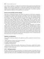
Joining process selection matrix
The joining process selection methodology is based on the same matrix approach used for
manufacturing process selection. Again, due to page size constraints and the number of
processes to be detailed, each process has been assigned an identification code rather than
using process names. The key to the joining processes used in the matrix is shown in Figure 2.5
together with the relevant PRIMA number, where information can be found regarding
that individual process or joining technology. Due to size constr aints, the joining process
selection matrix is divided into two parts; Figures 2.6(a) and (b) toget her show the complete
matrix.
The matrix representation of the selection technique provides an intuitive way of navigating
a large quantity of data. This makes the selection process simple and quick to use. Supporting
the selection matrix with design advice through the use of the PRIMAs completes the
Fig. 2.5 Key to joining process PRIMA selection matrix.
PRIMA selection strategies 31
//SYS21///INTEGRAS/B&H/PRS/FINALS_07-05-03/0750654376-CH002.3D – 32 – [19–34/16] 13.5.2003 7:43PM
IRONS
THIN
£3mm
STEEL
(carbon)
STEEL
(tool, alloy)
STAINLESS
STEEL
COPPER
& ALLOYS
ALUMINIUM
& ALLOYS
MAGNESIUM
& ALLOYS
ZINC
& ALLOYS
TIN
& ALLOYS
[W6][W13]
[W15][B1]
[W6][W13]
[W15][B1]
[F19][F20]
[F23]
[F19][F20]
[F23]
[W3][W6]
[W8][W9]
[W11][W13]
[W14][W15]
[B1]
[W3][W6]
[W9] [W11]
[W13][W14]
[W15] [B1]
[W6][W7]
[W9][W10]
[W13][W15]
[F20]
[W2][W3]
[W6][W8]
[W9][W11]
[W13][W14]
[W15][B1]
[W2][W3]
[W9][W11]
[W13][W14]
[W15][B1]
[W3][W7]
[W9][W10]
[W13][W15]
[F20]
[F19][F20]
[F19][F20]
[W2][W3]
[W6][W8]
[W9][W11]
[W13][W14]
[W15][B1]
[W2][W3]
[W9][W11]
[W13][W14]
[W15][W17]
[B1]
[W9][W10]
[W13][W15]
[W17]
[F20] [F19][F20] [F19][F20]
[W1] [W1]
[S1][S8]
[W1][W2]
[W3][W9]
[W13][W14]
[B1]
[W1][W2]
[W3][W9]
[W13][B1]
[W3][W7]
[W9] [W13]
[F19][F23] [F19][F23]
[W1][W2]
[W3][W6]
[W8][W9]
[W11][W13]
[W14][B1]
[W1][W2]
[W3][W6][W9]
[W11][W13]
[W14][B1]
[W3][W9]
[S1][S8]
[F23] [F23]
[W3][W8]
[W9][W13]
[W14][B1]
[W3][W9]
[W4][W13]
[W14]
[W13]
[F23] [F23]
[S1][S8]
[F23] [F23]
[W13]
[W15]
[W16]
[W17][B1]
[W13]
[W15]
[W16]
[W17]
[F19][F20]
[F23]
[F19][F20]
[F23]
[W3][W9]
[W11][W13]
[W14] [W15]
[W16][W17]
[B1]
[W9] [W13]
[W15][W16]
[W17]
[F20]
[F19][F20]
[W2][W3]
[W8][W9]
[W11] [W13]
[W14][W15]
[B1][B6]
[W2][W3]
[W9][W11]
[W13][W14]
[W15] [W17]
[W16][B1]
[W3][W9]
[W13][W15]
[W16][W17]
[F20]
[F19][F20]
[F19][F20]
[W2][W3]
[W8][W9]
[W11][W13]
[W14][W15]
[B1][B6]
[W2][W3]
[W9][W11]
[W13][W14]
[W15][W16]
[B1]
[W3][W9]
[W13][W15]
[W16][W17]
[F20]
[F19][F20]
[F19][F20]
[W1][W2]
[W3][W9]
[W13] [W14]
[B1]
[W2][W3]
[W9][W13]
[B1]
[W3][W9]
[W13]
[F19][F23] [F19][F23]
[W3][W9]
[S1][S8]
[F23] [F23]
[W3][W8][W9]
[W13][W14]
[B1][B6]
[W4][W3]
[W9][W13]
[W14]
[W13]
[F23] [F23]
[S1][S8]
[F23] [F23]
[W16]
[W17][B2]
[B4]
[W16]
[W17][B4]
[W8][W11]
[W13][W14]
[W19][B2]
[B4][B6]
[W11][W13]
[W14][W16]
[W17][W19]
[B2] [B4]
[W13][W16]
[W17]
[W2][W8]
[W11][W13]
[W14][W19]
[B2][B4][B6]
[W2][W11]
[W13][W14]
[W16][W17]
[W19][B2]
[B4]
[W13][W16]
[W17]
[F11]
[W2][W8]
[W11][W13]
[W14][W19]
[B2][B4][B6]
[W2][W11]
[W13][W14]
[W16][W17]
[W19][B2]
[B4]
[W13][W16]
[W17]
[F11][S6]
[W1][W2]
[W13][W14]
[W19][B2]
[B4]
[W2][W13]
[B2]
[W1][W2]
[W8][W11]
[W13][W14]
[W19][B2]
[B4][B6]
[W1][W2]
[W11][W13]
[W14][W19]
[B2][B6]
[S2][S6][S8]
[W8][W13]
[W14][B2]
[B4][B6]
[W4][W13]
[W14]
[W13]
[S2][S6][S8]
[W18][B2]
[B3][B4][B8]
[B2][B3]
[B4][B8]
[W8][W11]
[W13][W14]
[W18][W19]
[W20][B2][B3]
[B4][B5][B7]
[B8][F7] [F9]
[W4][W13]
[W16][W17][B3]
[B8]
[W8][W11]
[W14][W18]
[W19][W20]
[B2][B3][B4]
[B5][B7][B8]
[W4][W11]
[W14][W16]
[W17][W18]
[W19][W20]
[B2][B3][B4]
[B8]
[W4][W16]
[W17][B3]
[B8]
[F11]
[W8][W11]
[W14][W18]
[W19][W20]
[B2][B3][B4]
[B5][B7][B8]
[F7][F9]
[W4][W11]
[W14][W16]
[W17][W18]
[W19][W20]
[B2][B3][B4]
[B8]
[W4][W16]
[W17][B3]
[B8]
[F11][S3]
[S2][S3][S4]
[S5][S7][S9]
[W18] [W19]
[W20][B2]
[B3][B4][B5]
[B8][F7][F9]
[W4][W18]
[W20][B2]
[B3][B8]
[B3][B8]
[W4][W8]
[W11][W14]
[W18][W19]
[W20][B2][B3]
[B4][B5][B7]
[B8][F7][F9]
[W4][W11]
[W14][W19]
[B2][B3][B8]
[B8]
[S2][S3][S4]
[S5][S7][S9]
[W8][W14]
[W18][W20]
[B2][B3]
[B4][B8]
[W4][W14]
[W18][W20]
[B3][B8]
[S2][S3][S4]
[S5][S7][S9]
[B3][B8] [B3][B8]
[W18][W20]
[W21] [B3]
[B8][F7][F9]
[W4][W18]
[W20] [W21]
[B3][B8]
[W4][W21]
[B3][B8]
[W18][W20]
[W21][B3]
[B8]
[W4][W18]
[W20][W21]
[B3] [B8]
[W4][W21]
[B3] [B8]
[F11]
[W18][W20]
[W21][B3]
[B8][F7][F9]
[W4][W18]
[W20][W21]
[B3] [B8]
[W4][W21]
[B3][B8]
[F11][S3]
[S3][S9]
[W18][W20]
[W21] [B3]
[B8][F7][F9]
[W4][W18]
[W20][W21]
[B3][B8]
[W21][B3]
[B8]
[W4][W18]
[W20][W21]
[B3][B8][F7]
[F9]
[W4][W21]
[B3][B8]
[W18][W20]
[B3][B8]
[W18][W20]
[W21][B3]
[B8]
[W21]
[S3][S9]
VERY LOW
1 TO 100
LOW
100 TO 1,000
LOW TO MEDIUM
1,000 TO 10,000
MEDIUM TO HIGH
10,000 TO 100,000
HIGH
100,000+
ALL QUANTITIES
[F1][A1]
[A2][A4]
[A5][A8]
[A10]
[F1]
[F12][F13] [F12][F13]
[F15][F16]
[F18][F21]
[F15][F18]
[F21]
[W5][W12]
[A1][A2][A4]
[A5][A8][A10]
[F1][F5][F6]
[F8][F10]
[W12][A1]
[A2][A4]
[A5][A10][F1]
[F1]
[A9][F14] [F12][F13] [F12][F13]
[F15][F17]
[F21]
[F15][F17]
[F18][F21]
[F15][F17]
[F21]
[W5][W12]
[F1][A1][A2]
[A4][A5][A8]
[A10]
[F1][A1][A2]
[A4][A5][A10]
[F1]
[F13][A9] [F12][F13] [F12][F13]
[F15][F17]
[F21]
[F15][F17]
[F21]
[F15][F17]
[F21]
[W5][W12]
[F1][F5][F6]
[F8][F10]
[A4]
[A10]
[W12][F1]
[A4] [A10]
[F1]
[F13][A9]
[F14]
[F12][F13] [F12][F13]
[F15][F17]
[F21]
[F15][F17]
[F18[F21]
[F15][F17]
[F18[F21]
[W12][F2]
[F10][F14]
[A4]
[W12][F2]
[F2]
[F13][A9]
[F14]
[F13]
[F16][F21] [F16][F21] [F21]
[W12][F1]
[F5][F6][F8]
[F10][A1]
[A2][A4]
[A5][A10]
[W12][F1]
[F10][A4]
[A10]
[F1]
[A9][F13]
[F14]
[F12][F13] [F12][F13]
[F16][F21]
[F16][F18]
[F21]
[F18][F21]
[W5][W12]
[F1][F2][F5]
[F6] [F8][F10]
[A2][A4][A5]
[A7][A10]
[W5][W12]
[F1][F2][A2]
[A4][A5][A7]
[A10]
[F1][F2]
[F13]
[A9]
[F14]
[F12][F13] [F12][F13]
[F15][F16]
[F17][F21]
F[15][F16]
[F17][F18]
[F21]
[F15][F17]
[F18][F21]
[W12][F1]
[F2][A1][A4]
[A5]
[W12][F1]
[F2][A4]
[A5]
[F1][F2]
[F13][A9]
[F16][F21]
[F16][F18]
[F21]
[F18][F21]
[W12][F2]
[F10][F14]
[W12][F2] [F2]
[F15][F16]
[F21]
[F15][F16]
[F18][F21]
[F15][F18]
[F21]
[S2][S3][S4]
[S5][S7] [S9]
[S2][S6] [S8]
[S1][S8]
[S1][S8]
[W1][W2]
[W3][W8]
[W9][W11]
[W13][W14]
[B1][B6]
[W21][B8]
[W1] [W1]
[S1][S8]
[W1] [W1]
[S1][S6][S8]
[W1][W2]
[W3][W9]
[W11][W13]
[W14]
[B1][B6]
[W3][W8]
[W9][W11]
[W13][W14]
[W15][B1]
[B6]
[W4][W11][W13]
[W14][W16]
[W17][W18]
[W19][W20]
[B2][B3][B4][B8]
[S3] [S9]
[S1]
[S1]
[S6]
[S3]
[S3]
[S1]
[S1]
[S3] [S9]
[F12][F13] [F12][F13]
[F14]
[W19]
[W19]
[F11] [F11]
[F11] [F11]
MATERIAL &
THICKNESS
QUANTITY &
PERMANENCE
MED.
3 to
19mm
THICK
³19mm
NP
SP
P
NP
SP
P
NP
SP
P
NP
SP
P
NP
SP
P
NP
SP
P
MED.
3 to
19mm
THICK
³19mm
THIN
£3mm
MED.
3 to
19mm
THICK
³19mm
THIN
£3mm
MED.
3 to
19mm
THICK
³19mm
THIN
£3mm
MED.
3 to
19mm
THICK
³19mm
THIN
£3mm
MED.
3 to
19mm
THICK
³19mm
THIN
£3mm
MED.
3 to
19mm
THICK
³19mm
THIN
£3mm
MED.
3 to
19mm
THICK
³19mm
THIN
£3mm
MED.
3 to
19mm
THICK
³19mm
[F19][F20]
[F19][F20]
[F19][F20]
Note - The joining process PRIMA selection matrix cannot be considered as comprehensive and should not be taken as such. It represents the main common industrial practice, but there will always be
exceptions at this level of detail. Also, the order in which the PRIMAs are listed in the nodes of the matrix has no significance in terms of preference. Dissimilar metals also accounts for joining metals with coatings.
Fig. 2.6 (a) Joining process PRIMA selection matrix ^ part A.
32 Selecting candidate processes
//SYS21///INTEGRAS/B&H/PRS/FINALS_07-05-03/0750654376-CH002.3D – 33 – [19–34/16] 13.5.2003 7:43PM
LEAD
& ALLOYS
NICKEL
& ALLOYS
TITANIUM
& ALLOYS
THERMOPLASTICS
THERMOSETS
FR
COMPOSITES
CERAMICS
REFRACTORY
METALS
PREC-
IOUS
METALS
DISSIMILAR
MATERIALS
[W1] [W1]
[S1][S8]
[F23]
[F23]
[W2][W3]
[W6][W8]
[W9][W11]
[W13][W14]
[W15]
[W2][W3]
[W9][W11]
[W13][W14]
[W15]
[W9][W10]
[W13][W15]
[S1][S8]
[F20] [F20] [F20]
[W2][W3]
[W9][W13]
[W14]
[W2][W3]
[W9][W13]
[W14]
[W3][W9]
[W13]
[W22] [W22] [W22]
[S1]
[F22] [F22]
[W2][W3]
[W8][W9]
[W13][W14]
[B1]
[W2][W3]
[W9][W13]
[W3] [W1][W2]
[S1][S8]
[W2][W3]
[W8][W9]
[W11][B1]
[W2][W3]
[W9][W11]
[B1]
[W3][W9]
[F20]
[F19][F20]
[F22]
[F19][F20]
[F22]
[W1][W14] [W1][W14]
[S1][S8]
[F23]
[F23]
[W2][W3]
[W8][W9]
[W11][W13]
[W14][W15]
[B6]
[W2][W3]
[W9][W11]
[W13][W14]
[W15][W16]
[W9][W13]
[W15]
[S1][S8]
[F20] [F20] [F20]
[W2][W3]
[W9][W13]
[W14]
[W2][W3]
[W9][W13]
[W14]
[W3][W9]
[W13]
[W22] [W22] [W22]
[W2][W3]
[W8][W9]
[W13][W14]
[B1]
[W2][W3]
[W9][W13]
[W4] [W1][W2]
[S1][S8]
[W2][W3]
[W9][W8]
[W11][B1]
[W2][W3]
[W9][W11]
[B1]
[W3][W9]
[S1][S8]
[F20]
[F19][F20]
[F22]
[F19][F20]
[F22]
[W1][W14]
[S2][S6][S8]
[S2][S3][S4]
[S5][S7]
[S9]
[W2][W13]
[W14][W19]
[B4]
[W2][W13]
[W14][W19]
[W13]
[S2][S3][S6]
[F22] [F22]
[W2][W8]
[W14][B2]
[B4]
[W2] [W2] [W1]
[S2][S8]
[W2][W8]
[W11][W19]
[B2]
[W2][W11]
[B2]
[S2][S3][S6]
[S8][F11]
[F11]
[F22] [F22]
[W8][W11]
[W14][W18]
[W20][B3]
[B4][B5][B7]
[B8][F9]
[W4][W11]
[W14][W16]
[W18][W20]
[B3][B8]
[W4][B3][B8]
[S2][S3][S4]
[S5] [S7][S9]
[W8][W14]
[W18][W19]
[W20][B3]
[B4][B7][B8]
[W4][W14]
[W18][W19]
[W20][B3]
[B8]
[B3][B8]
[S7]
[F7]
[F11] [F11]
[F7]
[F11]
[S2][S3][S4]
[S5][S7]
[W18][B2]
[B4][B5]
[B7][B8]
[W4][W18]
[S2][S3][S4]
[S5]
[W8][W11]
[W19][W20]
[B2][B3][B8]
[F7][F9]
[W4][W11]
[W20][B2]
[B3][B8]
[W4][B3][B8]
[S2][S3][S4]
[S5][S7][F11]
[F11]
[S3][S9]
[W18][W20]
[W21][B3]
[B8][F9]
[W4][W18]
[W20][W21]
[B3] [B8]
[W4][W21]
[B3][B8]
[S3][S9]
[W18][W20]
[W21][B3]
[B8]
[W4][W18]
[W20][W21]
[B3][B8]
[W21][B3]
[B8]
[F7]
[F11] [F11]
[F7]
[F11]
[W18][W21]
[B8]
[W4][W18]
[W21]
[W20][W21]
[B3][B8][F7]
[F9]
[W4][W20]
[W21][B3]
[B8]
[W4][B3][B8]
[F11] [F11]
VERY LOW
1 TO 100
LOW
100 TO 1,000
LOW TO MEDIUM
1,000 TO 10,000
MEDIUM TO HIGH
10,000 TO 100,000
HIGH
100,000+
ALL QUANTITIES
[F2][F10]
[A1][A4]
[F2][F10][A4] [F2]
[F16][F21] [F16][F21] [F21]
[W5][W12]
[F1][A4][A8]
[W12][F1]
[A4]
[F1]
[F13] [F12][F13] [F12][F13]
[F15][F16]
[F17][F21]
[F15][F16]
[F17][F18]
[F21]
[F15][F17]
[F18][F21]
[W12][A11] [A11]
[A9]
[F15][F17]
[F21]
[F15][F17]
[F18][F21]
[F15][F17]
[F18][F21]
[W5][F2][F3]
[F1][F4] [F6]
[F10] [A2]
[A4][A8]
[A10]
[F2][F3]
[F1][F10]
[A2][A4][A8]
[A10]
[F1][F2]
F3][A4]
[A10]
[A9]
[F17][F21]
[F23]
[F17][F18]
[F21] [F23]
[F17][F18]
[F21] [F23]
[F2][F3][F4]
[F10][A2][A4]
[A7][A8]
[F2][F3][A2]
[A4][A7][A8]
[F2][F3][A7]
[F16][F17]
[F21][F23]
[F15][F16]
[F17][F18]
[F21] [F23]
[F15][F17]
[F18][F21]
[F23]
[F2][F4][A2]
[A4][A7]
[A8][A10]
[A2][A4][A7]
[A8][A10]
[A4]
[F16][F17]
[F21][F23]
[F16][F17]
[F21][F23]
[F21][F23]
[F2][A2][A4]
[A5][A7][A8]
[A10]
[F10][A2][A4]
[A5][A7][A8]
[A10]
[F10][A2][A4]
[A5][A7][A8]
[A10]
[F13] [F12][F13] [F13]
[F15][F17]
[F21]
[F15][F17]
[F18][F21]
[F15][F17]
[F18][F21]
[F1] [F1] [F1]
[F13] [F12][F13] [F12][F13]
[F18][F21] [F18][F21]
[W5][F1]
[F8][A4]
[F16][F17]
[F18][F21]
[W5][W12]
[F1][F2][F5]
[F6][F10]
[W12][F1]
[F2][F10]
[F1]
[F13][F14] [F12][F13] [F12][F13]
[F15][F16]
[F17][F18]
[F21][F23]
[F15][F16]
[F17][F18]
[F21][F23]
[F15][F17]
[F18][F21]
[F23]
[W2][W8]
[W9][W11]
[W13][W14]
[B4][B6]
[W2][W11]
[W13][W14]
[W16]
[W13]
[S2][S6][S8]
[S1]
[F22] [F22]
[S1][S8]
[W1][W14]
[F21]
[W14][W14]
[W4]
[W4] [W21]
[F11] [F11] [F11]
[F11] [F11]
[F11]
[F11]
[F11]
[F11]
[F11]
[A9]
[F12] [F12]
[F11] [F11]
[F11] [F11]
[F12] [F12]
MATERIAL &
THICKNESS
QUANTITY &
PERMANENCE
NP
SP
P
NP
SP
P
NP
SP
P
NP
SP
P
NP
SP
P
NP
SP
P
THIN
£3mm
MED.
3 to
19mm
THICK
³19mm
THIN
£3mm
MED.
3 to
19mm
THICK
³19mm
THIN
£3mm
MED.
3 to
19mm
THICK
³19mm
THIN
£3mm
MED.
3 to
19mm
THICK
³19mm
THIN
£3mm
MED.
3 to
19mm
THICK
³19mm
THIN
£3mm
MED.
3 to
19mm
THICK
³19mm
THIN
£3mm
MED.
3 to
19mm
THICK
³19mm
THIN
£3mm
MED.
3 to
19mm
THICK
³19mm
THIN
£3mm
MED.
3 to
19mm
THICK
³19mm
THIN
£3mm
Note - The joining process PRIMA selection matrix cannot be considered as comprehensive and should not be taken as such. It represents the main common industrial practice, but there will always be
exceptions at this level of detail. Also, the order in which the PRIMAs are listed in the nodes of the matrix has no significance in terms of preference. Dissimilar metals also accounts for joining metals with coatings.
Fig. 2.6 (b) Joining process PRIMA selection matrix ^ part B.
PRIMA selection strategies 33
//SYS21///INTEGRAS/B&H/PRS/FINALS_07-05-03/0750654376-CH002.3D – 34 – [19–34/16] 13.5.2003 7:43PM
methodology, allowing the user to both identify and gain an understanding of suitable joining
processes. Combining material thickness with material type is a logical way of allowing the
user to describe the material. It is also convenient to state quantity and then permanence in the
rows of the matrix.
2.4 PRIMA categories
A complete list of all PRIMAs presented in this section of the book is shown in Figure 2.7 for
reference.
Fig. 2.7 PRIMA categorie s and individual processes.
34 Selecting candidate processes
//SYS21///INTEGRAS/B&H/PRS/FINALS_07-05-03/0750654376-CH002-1.3D – 35 – [35–248/214] 9.5.2003 2:05PM
1 Casting processes
//SYS21///INTEGRAS/B&H/PRS/FINALS_07-05-03/0750654376-CH002-1.3D – 36 – [35–248/214] 9.5.2003 2:05PM
1.1 Sand casting
Process description
.
Moist bonding sand is packed around a pattern. The pattern is removed to create the mold, and
molten metal poured into the cavity. Risers supply necessary molten material during solidification.
The mold is then broken to remove the part (see 1.1F).
Materials
.
Most metals, particularly ferrous and aluminum alloys. Some difficulty encountered in casting lead,
tin and zinc alloys, also refractory alloys, beryllium, titanium and zirconia alloys.
Process variations
.
Green sand casting: the most common and the cheapest. Associated problems are that the mold
has low strength and high moisture content.
.
Dry sand: core boxes are used instead of patterns, and an oven is used to cure the mold. Expensive
and time consuming.
.
Skin-dried sand: the mold is dried to a certain depth. Used in the casting of steels.
.
Patterns: one-piece solid patterns are the cheapest to make; split patterns for moderate quantities;
match plate patterns for high volume production.
.
Wooden patterns: for low-volume production only.
.
Metal patterns: for medium to high-volume production. Hard plastics are also being used increasingly.
.
Cosworth casting: low pressure filling of mold used for better integrity, accuracy and porosity of
casting. Longer production times and higher tooling costs, however.
1.1F Sand casting process.
36 Selecting candidate processes
//SYS21///INTEGRAS/B&H/PRS/FINALS_07-05-03/0750654376-CH002-1.3D – 37 – [35–248/214] 9.5.2003 2:05PM
Economic considerations
.
Production rates of 1–50/h, but dependent on size.
.
Lead time typically days, but depending on complexity and size of casting.
.
Material utilization low to moderate. Twenty to fifty per cent of material lost in runners and risers.
.
Both mold material and runners and risers may be recycled.
.
Patterns easy to make and set, and reusable.
.
Pattern material dependent on the number of castings required.
.
Easy to change design during production.
.
Economical for low production runs of less than 100. Can be used for one-offs and high production
volumes depending on degree of automation.
.
Tooling costs low.
.
Equipment costs low.
.
Direct labor costs high. Can be labor intensive.
.
Finishing costs can be high. Cleaning and fettling required to remove gates and risers before
secondary processing. Parting lines may also need finishing by hand.
Typical applications
.
Engine blocks
.
Manifolds
.
Machine tool bases
.
Pump housings
.
Cylinder heads
Design aspects
.
High degree of shape complexity possible. Limited only by the pattern.
.
Loose piece patterns can be used for holes and protrusions.
.
All intersecting surfaces must be filleted: prevents shrinkage cracks and eliminates stress concen-
trations.
.
Design of gating system for delivery of molten metal into mold cavity important.
.
Placing of parting line important, i.e. avoid placement across critical dimensions.
.
Bosses, undercuts and inserts possible, but at added cost.
.
Steel inserts can be used as heat flow barriers.
.
Cored holes greater than 16 mm.
.
Machining allowances usually in the range 1.5–6 mm.
.
Draft angle ranging 1–5
.
.
Minimum section typically 3 mm for light alloys, 6 mm for ferrous alloys.
.
Sizes ranging 25 g–400 t in weight.
Quality issues
.
Molding sand must be carefully conditioned and controlled.
.
Most casting defects can be traced to and rectified by sand content.
.
Casting shrinkage and distortion during cooling governed by shape, especially when one dimension
is much larger than the other two.
.
Extensive flat surfaces prone to sand expansion defects.
.
Inspection of castings important.
Sand casting 37
//SYS21///INTEGRAS/B&H/PRS/FINALS_07-05-03/0750654376-CH002-1.3D – 38 – [35–248/214] 9.5.2003 2:05PM
.
High porosity and inclusion levels common in castings.
.
Defects in castings may be filled with weld material.
.
Castings generally have rough grainy surfaces.
.
Material strength inherently poor.
.
Castings have good bearing and damping properties.
.
If production volumes warrant the cost of a die.
.
Surface detail fair.
.
Surface roughness a function of the materials used in making the mold and ranging 3.2–50 mm Ra.
.
Not suitable for close specification of tolerances without secondary processing.
.
Process capability charts showing the achievable dimensional tolerances using various materials pro-
vided (see 1.1 CC). Allowances of Æ0.5–Æ2 mm should be added for dimensions across the parting line.
1.1CC Sand casting process capability charts.
38 Selecting candidate processes
//SYS21///INTEGRAS/B&H/PRS/FINALS_07-05-03/0750654376-CH002-1.3D – 39 – [35–248/214] 9.5.2003 2:05PM
1.2 Shell molding
Process description
.
A heated metal pattern is placed over a box of thermosetting resin-coated sand. The box is inverted
for a fixed time to cure the sand. The box is re-inverted, and the excess sand falls out. The shell is
then removed from the pattern and joined with the other half (previously made). They are supported
in a flask by an inert material ready for casting (see 1.2F).
Materials
.
Most metals, except: lead, zinc, magnesium and titanium alloys, also beryllium, refractory and
zirconia alloys.
Process variations
.
Molds produced from other casting processes may be joined with shell molds.
.
Patterns are generally made of iron or steel giving good dimensional accuracy.
.
Aluminum patterns may be used for low-volume production.
.
Other pattern materials used are plaster, and graphite for reactive materials.
Economic considerations
.
Production rates of 5–200/h, but dependent on size.
.
Lead time several days to weeks depending on complexity and size.
.
Material utilization high; little scrap generated.
1.2F Shell molding process.
Shell molding 39
//SYS21///INTEGRAS/B&H/PRS/FINALS_07-05-03/0750654376-CH002-1.3D – 40 – [35–248/214] 9.5.2003 2:05PM
.
Potential for automation high.
.
With use of gating systems several castings in a single mold possible.
.
Resin binders cost more, but only 5 per cent as much sand used as compared to sand casting.
.
Difficult to change design during production.
.
More suited to moderate to high volume production, but production volumes of 100–500 may be
economical.
.
Considered the best of low cost casting methods for large quantities.
.
Tooling costs low to moderate.
.
Equipment costs moderate to high.
.
Labor costs low to moderate.
.
Low finishing costs. Often no finishing required.
Typical applications
.
Small mechanical parts requiring high precision
.
Gear housings
.
Cylinder heads
.
Connecting rods
.
Transmission components
Design aspects
.
Good for molding complex shapes, especially when using composite molds.
.
Great variations in cross section possible.
.
Sharper corners, thinner sections, smaller projections than possible with sand casting.
.
Bosses and inserts possible.
.
Undercuts difficult.
.
Placing of parting line important, i.e. avoid placement across critical dimensions.
.
Cored holes greater than 13 mm.
.
Draft angle ranging 0.25–1
, depending on section depth.
.
Maximum section ¼ 50 mm.
.
Minimum section ¼ 1.5 mm.
.
Sizes ranging 10 g–100 kg in weight. Better for small parts less than 20 kg.
Quality issues
.
Blowing sand onto pattern makes d epositing more uniform, especially good for intricate forms.
.
Few castings scrapped due to blowholes or pockets. Gases are able to escape through thin shells or
venting.
.
Composite cores may include chills and cores to control solidification rate in critical areas.
.
Moderate porosity and inclusions.
.
Mechanical properties better than sand casting.
.
Uniform grain structure.
.
Surface detail good.
.
Surface roughness ranging 0.8–12.5 mm Ra.
.
Process capability charts showing the achievable dimensional tolerances using various materials
provided (see 1.2CC). Allowances of Æ0.25–Æ0.5 mm should be added for dimensions across the
parting line.
40 Selecting candidate processes
//SYS21///INTEGRAS/B&H/PRS/FINALS_07-05-03/0750654376-CH002-1.3D – 41 – [35–248/214] 9.5.2003 2:05PM
1.2CC Shell molding process capability chart .
Shell molding 41
//SYS21///INTEGRAS/B&H/PRS/FINALS_07-05-03/0750654376-CH002-1.3D – 42 – [35–248/214] 9.5.2003 2:05PM
1.3 Gravity die casting
Process description
.
Molten metal is poured under gravity into a pre-heated die, where it solidifies. The die is then opened
and the casting ejected. Also known as permanent mold casting (see 1.3F).
Materials
.
Usually non-ferrous metals, for example: copper, aluminum, magnesium, but sometimes iron, lead,
nickel, tin and zinc alloys. Carbon steel can be cast with graphite dies.
Process variations
.
Dies typically cast iron, graphite or refractory material.
.
Metal or sand cores can be used although surface finish can be poor.
.
Low pressure die casting: uses low-pressure (1 bar) air to force the molten metal into the die cavity.
Less popular than gravity die casting, and tends to be used purely for the production of car wheels.
Gives lower production rates.
.
Slush casting: for creating hollow parts without cores in low melting point metals such as lead, zinc
and copper alloys.
Economic considerations
.
Production rates of 5–50/h, but dependent on size.
.
Lead times can be many weeks.
.
Material utilization moderate to high (10–40 per cent lost in scrap, but can be recycled).
.
If accuracy and surface finish not an issue, can use sand cores instead of metallic or graphite for
greater economy.
1.3F Gravity die casting process.
42 Selecting candidate processes
//SYS21///INTEGRAS/B&H/PRS/FINALS_07-05-03/0750654376-CH002-1.3D – 43 – [35–248/214] 9.5.2003 2:05PM
.
Production volumes of 500–1000 may be viable, but suited to higher volume production.
.
Tooling costs moderate.
.
Equipment costs moderate.
.
Labor costs low to moderate.
.
Finishing costs low to moderate. Gates need to be removed.
Typical applications
.
Cylinder heads
.
Engine connecting rods
.
Pistons
.
Gear and die blanks
.
Kitchen utensils
.
Gear blanks
.
Gear housings
.
Pipe fittings
.
Wheels
Design aspects
.
Shape complexity limited by that obtained in die halves.
.
Undercuts are possible with large added cost.
.
Inserts possible with small added cost.
.
Machining allowances usually in the range 0.8–1.5 mm.
.
Vertical parting lines commonly used.
.
Placing of parting line important, i.e. avoid placement across critical dimensions.
.
Cored holes greater than 15 mm.
.
Draft angle ranging 2–3
.
.
Maximum section ¼ 50 mm.
.
Minimum section ¼ 2 mm.
.
Sizes ranging from 50 g to 300 kg in weight. Commonly used for castings less than 5 kg.
Quality issues
.
Little porosity and inclusions: can be minimized by slow die filling to reduce turbulence.
.
Redressing of the dies may be required after several thousand castings.
.
Collapsible cores improve extraction difficulties on cooling.
.
‘Chilling’ effect of cold metallic dies on the surface of the solidifying metals needs to be controlled by
pre-heating at correct temperature.
.
Large castings sometimes require that the die is tilted as molten metal is being poured in to reduce
turbulence.
.
Mechanical properties fair to good.
.
Surface detail is good.
.
Surface roughness ranging 0.8–6.3 mm Ra.
.
Process capability charts showing the achievable dimensional tolerances using various materials
provided (see 1.3CC). Allowances of Æ0.25–Æ0.75 mm should be added for dimensions across the
parting line.
Gravity die casting 43