Process Engineering Equipment Handbook Episode 3 Part 2 ppt
Bạn đang xem bản rút gọn của tài liệu. Xem và tải ngay bản đầy đủ của tài liệu tại đây (2.7 MB, 50 trang )
Power Transmission P-165
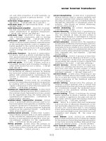
FIG. P-139 Generic hydrodynamic coupling types and dimensions in mm. (Source: J. M. Voith GmbH.)
P-166 Power Transmission
Geared variable-speed couplings for low-speed machines
Design and function. A reduction gear is located after the coupling for applications
in the drives of low-speed machines. The coupling and the gear are contained in a
common housing the lower part of which is designed as an oil tank.
By the optional installation of a hydrodynamic retarder with favorable braking
characteristics, a high retardation of large masses of the connected driven machine
is achieved.
Speed control is carried out by changing the oil-fill of the coupling through the
scoop tube that reaches into the working chamber of the coupling. The transmitted
power and the speed can be controlled steplessly. (See Fig. P-140.)
Oil supply. Working and lube oil are both supplied by the integrated oil tank,
however, from separate circuits. The oil supply for the motor and the driven
machine may also originate from this source.
Performance diagram. This serves to identify the appropriate coupling types and
sizes in relation to the input power and the required output speed.
Coupling types. Controlling low-speed machines such as coal mills, induced
draught fans, and crude oil pumps demands different coupling designs.
Depending on the application and for optimum adaptation to existing space
conditions, the gear stage is either designed as helical or bevel gear.
Genetic coupling types are as follows (see Fig. P-141):
1. A helical step-down gear is arranged behind the variable-speed turbocoupling.
This type is suitable for applications in coal mills, crushers, low-speed pumps,
and fans (Type R A).
2. Geared variable-speed coupling for low-speed driven machines with high
moment of inertia, e.g., coal mills. This type features a bevel gear stage behind
the turbocoupling (Type R B).
Torque Conversion*
A torque converter can be used where torque and speed have to be transmitted or
controlled between a driving and a driven machine in a simple and economical way.
A torque converter is “open” to both sides. It absorbs torque from the driving
machine and transmits it according to requirement to the driven machine. This
process is governed by the “natural” characteristics of the converter, or can be
controlled at will by varying the pitch of the guide blades (adjustable converter).
In both cases, the converter can be incorporated in a process control system.
In this prospectus, the attempt is made with examples to concisely yet clearly
describe the hydrodynamic torque converter, its characteristics, and its application
possibilities.
The most important areas of application are listed in Fig. P-142. Note symbols
in Fig. P-143.
When is it expedient to use a simple torque converter and when an adjustable
one? This varies from case to case. The most important criteria in this decision are
the characteristics of the prime mover and the load curve governed by the job to be
handled.
What is regulated, what is controlled?
See Figs. P-144 through P-146.
* Source: J.M. Voith GmbH, Germany.
Power Transmission P-167
FIG. P-140 Geared variable-speed coupling for low-speed machines. (Source: J. M. Voith GmbH.)
P-168 Power Transmission
FIG. P-141 Generic model of geared variable-speed couplings for low-speed machines. (Source:
J. M. Voith GmbH.)
FIG. P-142 Torque conversion applications. (Source: J. M. Voith GmbH.)
FIG. P-143 Symbols for a torque converter and an adjustable torque converter. (Source: J. M. Voith
GmbH.)
P-169
How the torque converter works
The pump impeller of the converter, a centrifugal pump, converts the torque M
P
absorbed from the motor into kinetic energy in a fluid mass. See Fig P-147.
In the turbine wheel the fluid mass is decelerated producing the turbine torque
M
T
. The guide wheel (reaction member) absorbs the differential torque M
R
between
input and output torque that results in the multiplication of torque. The ratio and
curve of torque multiplication M
T
/M
P
is conditioned by the form of the converter
blades.
FIG. P-144 Using a motor of constant speed and a torque converter without adjustment mechanism, jobs such as startups
can be undertaken smoothly and steplessly along the “natural” characteristic curve of the converter. This is a starting
process. The operating range is centered around peak efficiency. (Source: J. M. Voith GmbH.)
FIG. P-145 Using a variable-speed motor and a nonadjustable torque converter, a method of regulation is obtained that
permits any desired curve to be operated corresponding to the input/output speed ratio. This case illustrates how the
efficiency peak remains practically the same. (Source: J. M. Voith GmbH.)
FIG. P-146 Using a constant-speed motor and an adjustable torque converter, any operating point can be run within the
characteristic range of the turbine, e.g., a constant torque can be held under fluctuating load or specific speeds in
alternating succession. At first glance, an adjustable torque converter works uneconomically in specific ranges, because
the efficiency decreases with progressively closed guide blades. This is deceptive. If one projects the operating points from
the turbine characteristic range onto the efficiency curves, the result is a good overall efficiency. (Source: J. M. Voith
GmbH.)
144 145 146
P-170 Power Transmission
Power Transmission P-171
For this reason, every converter design has its own characteristic family of curves.
The integral gear pump produces the necessary operating pressure and dissipates
heat generated by directing the oil stream to the cooling unit.
Application case 1: Gas turbine starting
The gas turbine is loaded by its compressor and the mass of the generator. It cannot
be started without assistance. As a starting motor either an electric motor can be
1
2
3
4
1
4
2
3
FIG. P-147 Torque converter components. (Source: J. M. Voith GmbH.)
P-172 Power Transmission
used, providing that sufficient power can be taken from the mains, or alternatively
a diesel engine. See Fig. P-148.
Possible solutions. The torque converters shown in Figs. P-149 through P-152 can
be employed wherever large masses have to be accelerated rapidly and smoothly,
wherever high breakaway torque has to be overcome, and wherever speeds have to
be automatically adapted to loads.
A torque converter, however, is not only an efficient but also an economical
solution to a drive problem: low prime costs, low space requirements, and practically
wear-free operation are facts which speak for this.
Torque converters for gas turbine starting sets are particularly adaptable.
They can be supplied with a filling and draining facility of with a guide blade
adjustment mechanism; in all cases, the blading can be matched to the torque
loads to be handled. Previously supplied torque converters include those
with ratings up to 4000 kW at speeds of 3600 1/min (60 Hz) and 3000 1/min
(50 Hz).
The operating fluid for the torque converter is taken from the lube oil system of
the gas turbine. The oil tank simultaneously serves as a heat accumulator.
Application case 2: Variable-speed engine and fluctuating loads (Figs. P-153 through P-159)
Several diesel engines drive the drilling rods, lifting gear, and mud pumps through
a chain compound under constantly fluctuating load. During drilling, speeds must
be steplessly varied and shock loads absorbed. At the same time, the mud pumps
press flushing and ballast material into the drill-hole at different rates and
pressures to flush out the drill cuttings. The lifting gear works with high
acceleration and retardation when the, often, several thousand meters long drilling
rods need to be dismantled quickly. The automotive governed diesel engines, with
their available speed and torque capacity, are incapable of fulfilling these tasks
satisfactorily.
Possible solutions. Both types of converters are also suitable for other similarly
loaded machines, e.g., heavy earth-moving machines, light shunting locomotives,
FIG.
P-148 Schematic of a torque converter in a drivetrain. (Source: J. M. Voith GmbH.)
Power Transmission P-173
scrapers, loader plants, bucket dredgers, cranes, and winches. The converter
protects the plant from overload and overdrive, matches itself steplessly and
automatically to arising resistance, and dampens shock and vibration between
driving and driven machines. The use of a torque converter substantially increases
the length of life reliability of a plant.
FIG. P-149 Torque converter with constant filling. The gas turbine is brought out of standstill at a
high breakaway torque and is accelerated under increasing compression resistance to firing
speed. After this, hot combustion gases in the turbine support the compressor so that with
increasing speed the torque requirement decreases up to the self-sustaining speed of the turbine.
When this speed has been reached, the starting equipment is disengaged by means of an SSS-
clutch. The gas turbine oil tank serves as an accumulator for heat generated in the torque
converter. (Source: J. M. Voith GmbH.)
FIG. P-150 Torque converter with filling and draining control. With the torque converter drained,
the starting motor is accelerated up to rated speed. After this, the converter is filled and the gas
turbine started as under Fig. P-149. To disengage the starting equipment, the torque converter is
simply drained. A freewheeling device is dispensed with. (Source: J. M. Voith GmbH.)
FIG. P-151 Torque converter with filling and draining control and guide blade adjustment (C1). A
torque converter equipped in this way fulfills the functions described under Figs. P-149 and P-150.
Additionally, the gas turbine can be held constant at any required speed. A similar influence on
speed is obtained by varying the circulating oil flow, e.g., by accurately dosed ventilation of the oil
circuit (C2). (Source: J. M. Voith GmbH.)
151
P-174 Power Transmission
Application case 3: Speed and torque regulation (Figs. P-160 through P-165)
Reciprocating machines work at both low and high speed, mostly against a constant
pressure, and therefore require a constant torque. Rates of delivery should be
precisely and steplessly adjustable. High efficiency is desired throughout the entire
operating range. With explosive media, flameproof protection is to be provided.
Possible solution. An electric motor with constant speed and an adjustable torque
converter (torque converter with adjustable guide blade mechanism) form an ideal
variable drive unit for reciprocating pumps. It is easy to regulate and therefore
suitable for any process control; the efficiency is good when compared with that of
other types of regulation. Figure P-142 demonstrates that the adjustable torque
converter is used in reciprocating pump drives.
Torque converter (compact design Vorecon® type RWE)
In its most compact form, the RWE-type Vorecon comprises the main components
of a hydrodynamic adjustable torque converter, a fixed planetary gear, and a
revolving planetary gear in a common housing. (See Figs. P-166 and P-167.)
FIG. P-152 Torque converter models available. (A) Type E (L) 10z FG. Power rating = 1416 kW at
2950 1/min (gas turbine GTMS 9001 E, 50 Hz). Effective operating range 80 percent. Peak efficiency
34 percent. Optional: filling and draining facility or guide blade adjustment. (B) Type E 8.5 wG (F).
Power rating = 560 kW at 210 1/min (gas turbine TG 20/B2, 50 Hz). Special feature: 4-fold torque
multiplication. Optional: filling and draining facility. (Source: J. M. Voith GmbH.)
Power Transmission P-175
FIGS. P-153, P-154, P-155, P-156, P-157 A torque converter is mounted on the output end of each
diesel engine. A torque converter compensates automatically fluctuations in torque, isolates
vibrations, dampens shock loads, and can be overloaded. These qualities are of particular
significance in multiple drive plants with widely differing loads. The waste heat generated in the
converter is dissipated in an oil cooler. (Source: J. M. Voith GmbH.)
153
154
156
155
157
FIG. P-158 (A) Torque converter type C–B. Power range 50–1000 kW. Special features:
Synchronous converter (no torque absorption at full output speed); therefore, no overload
protection required. Effective operating range = 100 percent. Peak efficiency at 80 percent. Can be
flange-mounted on a diesel engine; own lube oil system (oil sump and mechanical oil pump).
Cooling via engine cooling unit or oil/air cooler (supplied as optional extra). (B) Torque converter
type E. . .y. Power range 50–1000 kW. Special features: High starting torque multiplication, no
engine lug-down. Effective operating range = 80 percent. Peak efficiency at 55 percent. Can be
flange-mounted on a diesel engine; own lube oil system (oil sump and mechanical oil pump).
Cooling via engine cooling unit or oil/air cooler (supplied as optional extra). (Source: J. M. Voith
GmbH.)
P-176 Power Transmission
Function. The Vorecon works on the principle of a power split.
The adjustable torque converter is used to “take off” a small part of the power
from the main shaft and feed it to the revolving planetary gear via the fixed
planetary gear.
By adjusting the position of the guide vanes of the torque converter, the output
speed is varied.
The major portion of the power is transmitted purely mechanically and thus with
hardly any loss via the main shaft and the planetary drive.
This produces a very high degree of efficiency for the entire unit over the speed
range.
For type RWE the speed range is approximately 60 to 100 percent.
Power Transmission P-177
Because of its short, coaxial form, the RWE is extremely space-saving and has
very low capital cost.
Applications. The principal applications for this version are in the drives of boiler
feed pumps, compressors, and other high-speed machinery with a limited speed
range.
Expanded speed range application (Vorecon® type RWS)
In addition to the torque converter, fixed gear, and revolving gear unit, the RWS
version has a hydrodynamic adjustable brake (retarder). (See Figs. P-168 and P-
169.)
Function. Operation of the Vorecon type RWS can in principle be split into two
operating ranges.
In operation range 1 the retarder is filled with oil and the torque converter is
drained. Torque support of the superimposing system is affected by the retarder
that has variable guide vanes. Adjusting the guide vanes alters the output speed.
On reaching the changeover point, the retarder is drained and the torque
converter “takes over” operating range 2.
The changeover point can be fixed between 70 and 85 percent of the nominal
speed by appropriate selection of gearing ratio, during the design phase.
This means that the optimum efficiency of the drive can be adjusted to the load
schedule of the plant.
The overall speed-regulating range of the Vorecon type RWS is approximately 45
to 100 percent.
It is this expanded speed range, compared with the RWE, that characterizes the
application areas of this version.
Relieved startup application (Vorecon® type RW)
In this type of RW multistage variable-speed drive, a hydrodynamic variable-speed
coupling with scoop tube and lockup clutch is incorporated in front of the torque
converter.
FIG.
P-159 Power versus efficiency characteristics of C–B and E . . . y converters. (Source. J. M.
Voith GmbH.)
P-178 Power Transmission
FIG. P-160 Schematic of a torque converter in a process pump train. (Source: J. M. Voith GmbH.)
FIGS.
P-161, P-162 Characteristics of torque converter used in reciprocating machinery trains.
(Source: J. M. Voith GmbH.)
FIG.
P-163 Torque converter schematic (see also Fig. P-164). (Source: J. M. Voith GmbH.)
161
160
163
162
Power Transmission P-179
The features of the variable-speed coupling enable type RW to be used if a
particularly wide range is required and/or if relieved startup of the drive motor is
needed. (See Figs. P-170 and P-171.)
Function. Its function is also split into two operating ranges.
In operating range 1 the power flow passes through the variable-speed coupling
and the revolving planetary gear. The speed is adjusted exclusively by changing the
quantity of oil in the runner parts of the coupling, using the adjustable scoop tube.
This covers the regulating from 10 to 80 percent of maximum speed.
In operating range 2 the lockup clutch is brought into operation and the converter
is filled with oil. The converter pump wheel rotates at the same speed as the drive
motor. Adjustment of the guide blades produces an increase in output speed from
80 to 100 percent.
FIG. P-164 Adjustable torque converter, type EL. Power range 15–1000 kW. Special features: 2.5-fold torque multiplication;
effective operating range = 140 percent; peak efficency with fully opened blades = 85 percent. Guide blade adjustment:
manual actuation via push-rod or handwheel, push-button operated via servomotor drive, controlled and regulated
electronically via governor or pneumatically via servocylinder. Versions: Input and output shafts horizontal or vertical shaft
ends with key. (Source. J. M. Voith GmbH.)
FIG. P-165 Governors for adjustable torque converters link up guide blade adjustment and plant control. They have
indicators for ideal and actual values and are supplied optionally as electronic variable-speed governors, or as constant-
speed or torque governors. (Source. J. M. Voith GmbH.)
164
165
FIG. P-166 Design scheme of Vorecon type RWE. C, torque converter; E, fixed gear; F, revolving
gear; G, oil supply; P
e
, input power; P
ü
, superimposed power; P
a
, output power. (Source. J. M.
Voith GmbH.)
FIG.
P-167 Performance characteristics (type RWE). (Source. J. M. Voith GmbH.)
P-180 Power Transmission
Power Transmission P-181
Because of its overall speed range from 10 to 100 percent, the RW multistage
variable-speed drive is used particularly for drives of large fans and pumps, e.g.,
100 percent boiler feed pumps.
Summary: Multistage variable-speed drives
The combination of hydrodynamic drive elements with a planetary gear and the
principle of superimposed power transmission has helped improve the level of
efficiency of variable-speed mechanical drive systems in areas not within the scope
of other drive solutions. (See Figs. P-172 through P-174.)
The principle of power splitting makes it possible to achieve efficiencies of over
95 percent over wide ranges of powers from 1000 to 50,000 kW and speeds from 100
to 20,000 rpm.
FIG. P-168 Design scheme of Vorecon type RWS. C, torque converter; D, hydrodynamic adjustable
brake (retarder); E, fixed planetary gear; F, revolving planetary gear. Oil feed and control not
illustrated. (Source. J. M. Voith GmbH.)
FIG. P-169 Performance characteristics (type RWS). (Source. J. M. Voith GmbH.)
Observations indicate the following:
Reliability: typical figures of 99.93 percent
Availability including overhaul times: a typical figure is 99.83 percent
Maintenance at intervals (TBOs) of up to 80,000 hours
Precise adjustability and fast response times
Compact design
Vibration damping
Can also be used in environments that are exposed to risk of explosion and that
are dusty, at extreme temperatures
FIG. P-170 (a) Design scheme of Vorecon type RW. A, variable-speed coupling with scoop tube; B,
lockup clutch; C, torque converter; D, hydrodynamic brake; E, fixed planetary gear; F, revolving
planetary gear. (b) Vorecon multistage variable-speed drive type RW 14-12 F7 driving the boiler
feed pumps at Mannheim power station (Germany). Input speed n
e
= 1490 rpm; power requirement
P
a
= 8500 kW; output speed n
a
= 5000 rpm. (Source. J. M. Voith GmbH.)
(a)
(b)
P-182 Power Transmission
Power Transmission P-183
FIG. P-171 Performance characteristics (see Fig. P-170b). (Source: J. M. Voith GmbH.)
FIG. P-172 Vorecon multistage variable-speed drive type RWS 10-9 E2 driving the boiler feed
pumps at Kajaani power station, Finland. Input speed n
e
= 1490 rpm; power requirement P
a
=
1430 kW; output speed n
a
= 6000 rpm. (Source: J. M. Voith GmbH.)
As previously noted, the multistage variable-speed drive is used in power stations,
steel plants, and chemical and petrochemical industries. Specific applications
include:
Boiler and reactor feed pumps
Coolant and condensate pumps
FIG. P-173 Vorecon type RWE 5 F3 driving a compressor in a Swedish refinery. Input speed n
e
=
2980 rpm; power requirement P
a
= 1530 kW; output speed n
a
= 15,030 rpm. (Source: J. M. Voith
GmbH.)
Pipeline and loading pumps
Piston pumps and compressors
Boiler fans and dust extraction fans
Centrifugal compressors
Beater wheel mills
Process compressors
A further application of the Vorecon, combined with an electric motor, is the
replacement of gas or steam turbines when modernizing existing plants.
Torque-Limiting Safety Coupling
Features
Adjustable release torque
Selected release torque remains constant
Precise point of release
Minimum downtime
Backlash-free power transmission
Compact, low-weight design
Low moment of inertia
Minimal maintenance requirements
Design (see Figs. P-175 and P-176)
The Safeset
®
coupling consists of a twin-walled pressure sleeve. This can be
pressurized up to 1000 bar using oil under high pressure, while a shear valve (shear
tube) ensures that the system is completely sealed. Larger couplings have more
than one shear tube.
A shear ring is fixed to the shaft. If any overload occurs, this shear ring breaks
off the top of the shear valve.
The friction load surfaces are specially treated to prevent any wear when the
coupling releases. To ensure that friction surfaces do not come into contact with
P-184 Power Transmission
FIG. P-174 Efficiency versus load coupling characteristics (see Figs. P-172 and P-173). (Source:
J. M. Voith GmbH.)
Power Transmission P-185
each other after release, antifriction bearings are fitted between the components
that rotate relative to one another. A plain bearing is sufficient for couplings
operated at low speeds.
The area around the pressure surfaces and bearing is filled with a special
oil. This oil supports constant friction coefficient and, in turn, precise release
torque.
In contrast to shear element couplings, the release torque of the Safeset
®
coupling
is not influenced by material fatigue, i.e., S-N data. The release torque always
remains constant. (See Fig. P-177.)
Operation
To start operation of the coupling, connect a Safeset
®
pump to the oil charge port
(see Fig. P-178) and release the shear valve slightly to allow oil to be pumped into
the pressurized sleeve. The operator can select the required oil pressure using a
calibration diagram that is provided for each coupling. (See Fig. P-179.)
The selected hydraulic pressure generates a defined friction load between the
pressure sleeve and shaft. This pressure determines the maximum torque that can
be transmitted (slip torque).
If the operating torque exceeds the selected slip torque, the shaft rotates within
the pressure sleeve. The shear ring is fixed to the shaft, so it also rotates and breaks
off the top of the shear tube. This causes an instantaneous drop in oil pressure and
releases the friction connection. (See Fig. P-180.)
The Safeset
®
coupling can be returned to operation after a minimum of delay by
replacing the tube and reapplying the pressure.
Since the release process does not cause any wear, no maintenance is required
apart from a regular oil change.
Permitted temperature range is -20 to +60°C. Temperatures exceeding this range
are possible with special measurements.
Operating procedure after overload
Follow Figs. P-181 through P-186.
Coupling types
Various design types and sizes are available to suit specific applications. See Figs.
P-187 through P-191.
FIG. P-175 A hollow steel sleeve is expanded by oil under pressure; this produces a friction
connection between a shaft and a hub. At overload the coupling instantaneously releases the oil
pressure and interrupts the drive. (Source: J. M. Voith GmbH.)
P-186 Power Transmission
FIG. P-176 Safety coupling (Safeset) components. 1, shaft; 2, hub; 3, hollow steel sleeve; 4,
antifriction bearings (on each side); 5, seals (on each side); 6, shear ring; 7, shear tube; 8, oil
charge port. (Source: J. M. Voith GmbH.)
Power Transmission P-187
The coupling size is determined by the required release torque. This torque must
be within the stated adjustment range. Practice has shown that in many cases, it
is useful to have a torque safety margin of at least 20 percent.
The torque can be set below the lower limit, thereby reducing release torque
accuracy. Less than 1/3 of the maximum value should never be used.
Safeset
®
ST series with sleeve bearing. For installation between a ground shaft
and hub, with low operating speeds. This type is not axially located and cannot
absorb axial thrust following release of the coupling. The sleeve bearing only
allows limited radial and bending forces following release. (See Table P-21 and
Fig. P-192.)
Safeset series SR-PF (heavy duty). This design is developed for heavy duties
and preferably in conjunction with gear couplings, metal membrane couplings
or universal joints. For this purpose connecting flanges on both sides are
provided.
The couplings are designed and manufactured according to the customer’s speci-
fications.
FIG. P-177 S–N curve for torque vs. load. (Source: J. M. Voith GmbH.)
FIG. P-178 Shear tube. (Source: J. M. Voith GmbH.)