Advanced Vehicle Technology Episode 2 Part 8 potx
Bạn đang xem bản rút gọn của tài liệu. Xem và tải ngay bản đầy đủ của tài liệu tại đây (277.87 KB, 20 trang )
The rotor slots which guide the rollers taper in width
towards their base, but their axes instead of being
radial have an appreciable trailing angle so as to
provide better control over the radial movement of
the rollers. The hollow rollers made of case- har-
dened steel are roughly 10 mm in diameter and there
are three standard roller lengths of 13, 18 and 23 mm
to accommodate three different capacity pumps.
The cam ring is subjected to a combined rolling
and sliding action of the rollers under the generated
pressure. To minimize wear it is made from heat
treated nickel-chromium cast iron. The internal
profile of the cam ring is not truly cylindrical, but
is made up from a number of arcs which are shaped
to maximize the induction of delivery of the fluid as
it circulates through the pump.
To improve the fluid intake and discharge flow
there are two elongated intake ports and two simi-
lar discharge ports at different radii from the shaft
axes. The inner ports fill or discharge the space
between the rollers and the bottoms of their slots
and the outer ports feed or deliver fluid in the space
formed between the internal cam ring face and the
lobes of the rotor carrier. The inner elongated
intake port has a narrow parallel trailing (transi-
tion) groove at one end and a tapered leading
(timing) groove at the other end. The inner dis-
charge port has only a tapered trailing (timing)
groove at one end. These secondary circumferential
groove extensions to the main inner ports provide
a progressive fluid intake and discharge action as
they are either sealed or exposed by the rotor
carrier lobes and thereby reduce shock and noise
which would result if these ports were suddenly
opened or closed, particularly if air has become
trapped in the rotor carrier slots.
Operating cycle of roller pump (Fig. 9.22(a and b))
Rotation of the drive shaft immediately causes the
centrifugal force acting on the rollers to move them
outwards into contact with the internal face of the
cam ring. The functioning of the pump can be
considered by the various phases of operation as
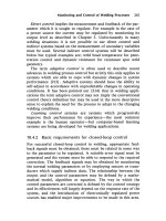
Fig. 9.21 (a and b) Power assisted steering double ball valve lock limit
332
an individual roller moves around the internal cam
face through positions A, B, C, D, E and F.
Filling phase (Fig. 9.22(a)) As the roller in posi-
tion A moves to position B and then to position C,
the space between the eccentric mounted rotor
carrier lobe and cam face increases. Therefore the
volume created between adjacent rollers will also
become greater. The maximum chamber volume
occurs between positions C and D. As a result,
the pressure in these chambers will drop and thus
induce fluid from the intake passages to enter by
way of the outer chamber formed by the rotor lobe
and the cam face and by the inner port into the
tapered roller slot region. Filling the two regions of
the chamber separately considerably speeds up the
fluid intake process.
Pressurization phase (Fig. 9.22(a)) With further
rotation of the rotor carrier, the leading edge of the
Fig. 9.22 (a and b) Power assisted roller type pump and control valve unit
333
rotor slot just beyond position C is just on the point
of closing the intake ports, and the space formed
between adjacent rollers at positions C and D starts
to decrease. The squeezing action pressurizes the
fluid.
Discharge phase (Fig. 9.22(a)) Just beyond
roller position D the inner discharge port is uncov-
ered by the trailing edge of the rotor carrier slot.
This immediately enables fluid to be pushed out
through the inner discharge port. As the rotor con-
tinues to rotate, the roller moves from position D
to E with a further decrease in radial chamber
space so that there is a further rise in fluid pressure.
Eventually the roller moves from position E to F.
This uncovers the outer discharge port so that an
increased amount of fluid is discharged into the
outlet passage.
Transition phase (Fig. 9.22(a)) The roller will
have completed one revolution as it moves from
position F to the starting position at A. During the
early part of this movement the leading edge of the
rotor slot position F closes both of the discharge
ports and at about the same time the trailing edge
of the rotor slot position A uncovers the transition
groove in readiness for the next filling phase. The
radial space between the rotor lobe and internal
cam face in this phase will be at a minimum.
Flow and pressure control valves
Description of the flow and pressure control valve
unit (Fig. 9.22(a and b)) The quantity of fluid
discharged from the roller type pump and the
build-up in fluid pressure both increase almost
directly with rising pump rotor speed. These char-
acteristics do not meet the power assisted steering
requirements when manoeuvring at low speed since
under these conditions the fluid circulation is
restricted and a rise in fluid pressure is demanded
to operate the power cylinders double acting pis-
ton. At high engine and vehicle speed when driving
straight ahead, very little power assistance is
needed and it would be wasteful for the pump to
generate high fluid pressures and to circulate large
amounts of fluid throughout the hydraulic system.
To overcome the power assisted steering mismatch
of fluid flow rate and pressure build-up, a com-
bined flow control and pressure relief valve unit is
incorporated within the cast iron pump housing.
The flow control valve consists of a spring loaded
plunger type valve and within the plunger body is
a ball and spring pressure relief valve. Both ends of
the plunger valve are supplied with pressurized
fluid from the pump. Situated in the passage
which joins the two end chambers of the plunger
is a calibrated flow orifice. The end chamber which
houses the plunger return spring is downstream of
the flow orifice.
Fluid from the pump discharge ports moves
along a passage leading into the reduced diameter
portion of the flow control plunger (Fig. 9.22(a)).
This fluid circulates the annular space surrounding
the lower part of the plunger and then passes along
a right angled passage through a calibrated flow
orifice. Here some of the fluid is diverted to the
flow control plunger spring chamber, but the
majority of the fluid continues to flow to the outlet
port of the pump unit, where it then goes through a
flexible pipe to the control valve built into the
steering box (pinion) assembly. When the engine
is running, fluid will be pumped from the discharge
ports to the flow control valve through the cali-
brated flow orifice to the steering box control
valve. It is returned to the reservoir and then finally
passed on again to the pump's intake ports.
Principle of the flow orifice (Fig. 9.22(a and b))
With low engine speed (Fig. 9.22(a)), the calibrated
orifice does not cause any restriction or apparent
resistance to the flow of fluid. Therefore the fluid
pressure on both sides of the orifice will be similar,
that is P
1
.
As the pump speed is raised (Fig. 9.22(b)), the
quantity of fluid discharged from the pump in a
given time also rises, this being sensed by the flow
orifice which cannot now cope with the increased
amount of fluid passing through. Thus the orifice
becomes a restriction to fluid flow, with the result
that a slight rise in pressure occurs on the intake
side of the orifice and a corresponding reduction in
pressure takes place on the outlet side. The net
outcome will be a pressure drop of P
1
±P
2
, which
will now exist across the orifice. This pressure dif-
ferential will become greater as the rate of fluid
circulation increases and is therefore a measure of
the quantity of fluid moving through the system in
unit time.
Operation of the flow control valve (Fig. 9.22
(a and b)) When the pump is running slowly the
pressure drop across the flow orifice is very small so
that the plunger control spring stiffness is sufficient
to fully push the plunger down onto the valve cap
stop (Fig. 9.22(a)). However, with rising pump
334
speed the flow rate (velocity) of the fluid increases
and so does the pressure difference between both
sides of the orifice. The lower pressure P
2
on the
output side of the orifice will be applied against the
plunger crown in the control spring chamber,
whereas the higher fluid pressure P
1
will act under-
neath the plunger against the annular shoulder area
and on the blanked off stem area of the plunger.
Eventually, as the flow rate rises and the pressure
difference becomes more pronounced, the hydrau-
lic pressure acting on the lower part of the plunger
P
1
will produce an upthrust which equals the
downthrust of the control spring and the fluid
pressure P
2
. Consequently any further increase in
both fluid velocity and pressure difference will
cause the flow control plunger to move back pro-
gressively against the control spring until the shoul-
dered edge of the plunger uncovers the bypass port
(Fig. 9.22(b)). Fluid will now easily return to the
intake side of the pump instead of having to work
its tortuous way around the complete hydraulic
system. Thus the greater the potential output of
the pump due to its speed of operation the further
back the plunger will move and more fluid will be
bypassed and returned to the intake side of the
pump. This means in effect that the flow output
of the pump will be controlled and limited irrespec-
tive of the pump speed (Fig. 9.23). The maximum
output characteristics of the pump are therefore
controlled by two factors; the control spring stiff-
ness and the flow orifice size.
Operation of the pressure relief valve (Fig. 9.22
(a and b)) The pressure relief valve is a small
ball and spring valve housed at one end and inside
the plunger type flow control valve at the control
spring chamber end (Fig. 9.22(a)). An annular groove
is machined on the large diameter portion of the
plunger just above the shoulder. A radial relief hole
connects this groove to the central spring housing.
With this arrangement the ball relief valve is
subjected to the pump output pressure on the
downstream (output) side of the flow orifice.
If the fluid output pressure exceeds some pre-
determined maximum, the ball will be dislodged
from its seat, permitting fluid to escape from the
control spring chamber, through the centre of the
plunger and then out by way of the radial hole and
annular groove in the plunger body. This fluid is
then returned to the intake side of the pump via the
bypass port.
Immediately this happens, the pressure P
2
in the
control spring chamber drops, so that the increased
pressure difference between both ends of the flow
control plunger pushes back the plunger. As a
result the bypass port will be uncovered, irrespect-
ive of the existing flow control conditions, so that a
rapid pressure relief by way of the flow control
plunger shoulder edge is obtained. It is the ball
valve which senses any peak pressure fluctuation
but it is the flow control valve which actually pro-
vides the relief passage for the excess of fluid. Once
the ball valve closes, the pressure difference across
the flow orifice for a given flow rate is again estab-
lished so that the flow control valve will revert back
to its normal flow limiting function.
9.2.6 Fault diagnosis procedure
Pump output check (Figs 9.12, 9.13, 9.15 and 9.18)
1 Disconnect the inlet hose which supplies fluid
pressure from the pump to the control (reaction)
valve, preferably at the control valve end.
2 Connect the inlet hose to the pressure gauge end
of the combined pressure gauge and shut-off
valve tester and then complete the hydraulic cir-
cuit by joining the shut-off valve hose to the
control valve.
3 Top up the reservoir if necessary.
4 Read the maximum pressure indicated on type
rating plate of pump or manufacturer's data.
5 Start the engine and allow it to idle with the shut-
off valve in the open position.
6 Close the shut-off valve and observe the max-
imum pressure reached within a maximum time
span of 10 seconds. Do not exceed 10 seconds,
otherwise the internal components of the
pump will be overworked and will heat up
excessively with the result that the pump will
be damaged.
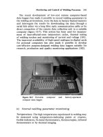
Fig. 9.23 Typical roller pump flow output and power
consumption characteristics
335
7 The permissible deviation from the rated pres-
sure may be Æ107. If the pump output is low,
the pump is at fault whereas if the difference is
higher, check the functioning of the flow and
pressure control valves.
An average maximum pressure figure cannot be
given as this will depend upon the type and appli-
cation of the power assistant steering. A typical
value for maximum pressure may range from
45 bar for a ram type power unit to anything up
to 120 bar or even more with an integral power
unit and steering box used on a heavy commercial
vehicle.
Power cylinder performance check (Figs 9.12, 9.13,
9.15 and 9.18)
1 Connect the combined pressure gauge and shut-
off valve tester between the pump and control
valve as under pump output check.
2 Open shut-off valve, start and idle the engine and
turn the steering from lock to lock to bleed out
any trapped air.
3 Turn the steering onto left hand full lock. Hold
the steering on full lock and check pressure read-
ing which should be within 10% of the pump
output pressure.
4 Turn the steering onto the opposite lock and
again check the pump output pressure.
5 If the pressure difference between the pump out-
put and the power cylinder on both locks is
greater than 10% then the power cylinder is at
fault and should be removed for inspection.
6 If the pressure is low on one lock only, this
indicates that the reaction control valve is not
fully closing in one direction.
A possible cause of uneven pressure is that the
control valve is not centralizing or that there is an
internal fault in the valve assembly.
Binding check A sticking or binding steering
action when the steering is moved through a por-
tion of a lock could be due to the following:
a) Binding of steering joint ball joints or control
valve ball joint due to lack of lubrication.
Inspect all steering joints for seizure and replace
where necessary.
b) Binding of spool or rotary type control valve.
Remove and inspect for burrs wear and
damage.
Excessive free-play in the steering If when turning
the driving steering wheel, the play before the steer-
ing road wheels taking up the response is excessive
check the following;
1 worn steering track rod and drag link ball joints
if fitted,
2 worn reaction control valve ball pin and cups,
3 loose reaction control valve location sleeve.
Heavy steering Heavy steering is experienced over
the whole steering from lock to lock, whereas bind-
ing is normally only experienced over a portion of
the front wheel steering movement. If the steering is
heavy, inspect the following items:
1 External inspection Ð Check reservoir level and
hose connections for leakage. Check for fan belt
slippage or sheared pulley woodruff key and
adjust or renew if necessary.
2 Pump output Ð Check pump output for low
pressure. If pressure is below recommended max-
imum inspect pressure and flow control valves
and their respective springs. If valve's assembly
appears to be in good condition dismantle pump,
examine and renew parts as necessary.
3 Control valve Ð If pump output is up to the
manufacturer's specification dismantle the con-
trol valve. Examine the control valve spool or
rotor and their respective bore. Deep scoring or
scratches will allow internal leaks and cause
heavy steering. Worn or damaged seals will also
cause internal leakage.
4 Power cylinder Ð If the control valve assembly
appears to be in good condition, the trouble is
possibly due to excessive leakage in the power
cylinder. If there is excessive internal power
cylinder leakage, the inner tube and power piston
ring may have to be renewed.
Noisy operation To identify source of noise, check
the following:
1 Reservoir fluid level Ð Check the fluid level as a
low level will permit air to be drawn into the
system which then will cause the control valve
and power cylinder to become noisy while oper-
ating.
2 Power unit Ð Worn pump components will
cause noisy operation. Therefore dismantle and
examine internal parts for wear or damage.
3 If the reservoir and pump are separately located,
check the hose supply from the reservoir to
pump for a blockage as this condition will
cause air to be drawn into the system.
336
Steering chatter If the steering vibrates or chat-
ters check the following:
1 power piston rod anchorage may be worn or
requires adjustment,
2 power cylinder mounting may be loose or incor-
rectly attached.
9.3 Steering linkage ball and socket joints
All steering linkage layouts are comprised of rods
and arms joined together by ball joints. The ball
joints enable track rods, drag-link rods and relay
rods to swivel in both the horizontal and vertical
planes relative to the steering arms to which they
are attached. Most ball joints are designed to tilt
from the perpendicular through an inclined angle
of up to 20
for the axle beam type front suspen-
sion, and as much as 30
in certain independent
front suspension steering systems.
9.3.1 Description of ball joint (Fig. 9.24(a±f))
The basic ball joint is comprised of a ball mounted
in a socket housing. The ball pin profile can be
divided into three sections; at one end the pin is
parallel and threaded, the middle section is tapered
and the opposite end section is spherically shaped.
The tapered middle section of the pin fits into a
similarly shaped hole made at one end of the steer-
ing arm so that when the pin is drawn into the hole
by the threaded nut the pin becomes wedged.
The spherical end of the ball is sandwiched
between two half hemispherical socket sets which
may be positioned at right angles to the pin's axis
(Fig. 9.24(a and b)). Alternatively, a more popular
arrangement is to have the two half sockets located
axially to the ball pin's axis, that is, one above the
other (Fig. 9.24(c±f)).
The ball pins are made from steel which when
heat treated provide an exceptionally strong tough
core with a glass hard surface finish. These proper-
ties are achieved for normal manual steering appli-
cations from forged case-hardened carbon (0.15%)
manganese (0.8%) steel, or for heavy duty power
steering durability from forged induction hardened
3% nickel 1% chromium steel. For the socket hous-
ing which might also form one of the half socket
seats, forged induction hardened steels such as a
0.35% carbon manganese 1.5% steel can be used. A
1.2% nickel 0.5% chromium steel can be used for
medium and heavy heavy duty applications.
9.3.2 Ball joint sockets (Fig. 9.24(c±f))
Modern medium and heavy duty ball and socket
joints may use the ball housing itself as the half
socket formed around the neck of the ball pin. The
other half socket which bears against the ball end
of the ball pin is generally made from oil impreg-
nated sintered iron (Fig. 9.24(c)); another type
designed for automatic chassis lubrication, an
induction hardened pressed steel half socket, is
employed (Fig. 9.24(d)). Both cases are spring loaded
to ensure positive contact with the ball at all times.
A helical (slot) groove machined across the shoulder
of the ball ensures that the housing half socket
and ball top face is always adequately lubricated
and at the same time provides a bypass passage to
prevent pressurization within the joint.
Ball and socket joints for light and medium
duty To reduce the risk of binding or seizure
and to improve the smooth movement of the ball
when it swivels, particularly if the dust cover is
damaged and the joint becomes dry, non-metallic
sockets are preferable. These may be made from
moulded nylon and for some applications the
nylon may be impregnated with molybdenum di-
sulphide. Polyurethane and Teflon have also been
utilized as a socket material to some extent. With
the nylon sockets (Fig. 9.24(e)) the ball pin throat
half socket and the retainer cap is a press fit in the
bore of the housing end float. The coil spring
accommodates initial settling of the nylon and sub-
sequent wear and the retainer cap is held in pos-
ition by spinning over a lip on the housing. To
prevent the spring loaded half socket from rotating
with the ball, two shallow tongues on the insert half
socket engage with slots in the floating half socket.
These ball joints are suitable for light and medium
duty and for normal road working conditions have
an exceptionally longer service life.
For a more precise adjustment of the ball and
socket joint, the end half socket may be positioned
by a threaded retainer cap (Fig. 9.24(f)) which is
screwed against the ball until all the play has been
taken up. The cap is then locked in position by
crimping the entrance of the ball bore. A Belleville
spring is positioned between the half socket and
the screw retainer cap to preload the joint and
compress the nylon.
9.3.3 Ball joint dust cover (Fig. 9.24(c±f))
An important feature for a ball type joint is its dust
cover, often referred to as the boot or rubber gaiter,
but usually made from either polyurethane or
nitrile rubber mouldings, since both these materials
have a high resistance to attack by ozone and do
not tend to crack or to become hard and brittle at
low temperature. The purpose of the dust cover is
337
Fig. 9.24 (a±f) Steering ball unit
338
to exclude road dirt moisture and water, which if
permitted to enter the joint would embed itself
between the ball and socket rubbing surfaces. The
consequence of moisture entering the working sec-
tion of the joint is that when the air temperature
drops the moisture condenses and floods the upper
part of the joint. If salt products and grit are
sprayed up from the road, corrosion and a mild
grinding action might result which could quickly
erode the glass finish of the ball and socket sur-
faces. This is then followed by the pitting of the
spherical surfaces and a wear rate which will
rapidly increase as the clearance between the rub-
bing faces becomes larger.
Slackness within the ball joint will cause wheel
oscillation (shimmy), lack of steering response,
excessive tyre wear and harsh or notchy steering feel.
Alternatively, the combination of grease, grit,
water and salts may produce a solid compound
which is liable to seize or at least stiffen the relative
angular movement of the ball and socket joint,
resulting in steering wander.
The dust boot must give complete protection
against exposure from the road but not so good
that air and the old grease cannot be expelled when
the joint is recharged, particularly if the grease is
pumped into the joint at high pressure, otherwise
the boot will burst or it may be forced off its seat so
that the ball and socket will become exposed to the
surroundings.
The angular rotation of the ball joint, which
might amount to 40
or even more, must be accom-
modated. Therefore, to permit relative rotation to
take place between the ball pin and the dust cover,
the boot makes a loose fit over the ball pin and is
restrained from moving axially by the steering arm
and ball pin shoulder while a steel ring is moulded
into the dust cover to prevent the mouth of the boot
around the pin spreading out (Fig. 9.24(c±f)). In
contrast, the dust cover makes a tight fit over the
large diameter socket housing by a steel band which
tightly grips the boot.
9.3.4 Ball joint lubrication
Before dust covers were fitted, ball joints needed to
be greased at least every 1600 kilometres (1000
miles). The advent of dust covers to protect the
joint against dirt and water enabled the grease
recharging intervals to be extended to 160 000 kilo-
metres (10 000 miles). With further improvements
in socket materials, ball joint design and the choice
of lubricant the intervals between greasing can be
extended up to 50 000 kilometres (30 000 miles)
under normal road working conditions. With the
demand for more positive and reliable steering,
joint lubrication and the inconvenience of periodic
off the road time, automatic chassis lubrication
systems via plastic pipes have become very popular
for heavy commercial vehicles so that a slow but
steady displacement of grease through the ball joint
system takes place. The introduction to split socket
mouldings made from non-metallic materials has
enabled a range of light and medium duty ball and
socket joints to be developed so that they are grease
packed for life. They therefore require no further
lubrication provided that the boot cover is a good
fit over the socket housing and it does not become
damaged in any way.
9.4 Steering geometry and wheel alignment
9.4.1 Wheel track alignment using Dunlop
optical measurement equipment Ð calibration of
alignment gauges
1 Fit contact prods onto vertical arms at approxi-
mately centre hub height.
2 Place each gauge against the wheel and adjust
prods to contact the wheel rim on either side of
the centre hub.
3 Place both mirror and view box gauges on a level
floor (Fig. 9.25(b)) opposite each other so that
corresponding contact prods align and touch
each other. If necessary adjust the horizontal
distance between prods so that opposing prods
are in alignment.
4 Adjust both the mirror and target plate on the
viewbox to the vertical position until the reflec-
tion of the target plate in the mirror is visible
through the periscope tube.
5 Look into the periscope and swing the indicator
pointer until the view box hairline is positioned
in the centre of the triangle between the two thick
vertical lines on the target plate.
6 If the toe-in or -out scale hairline does not align
with the zero reading on the scale, slacken off the
two holding down screws and adjust indicator
pointer until the hairline has been centred.
Finally retighten screws.
Toe-in or -out check (Fig. 9.25(a, b and c))
1 Ensure that tyre pressures are correct and that
wheel bearings and track rod ends are in good
condition.
2 Drive or push the vehicle in the forward
direction on a level surface and stop. Only take
339
readings with the vehicle rolled forward and
never backwards as the latter will give a false
toe angle reading.
3 With a piece of chalk mark one tyre at ground
level.
4 Place the mirror gauge against the left hand
wheel and the view box gauge against the right
hand wheel (Fig. 9.25(b)).
5 Push each gauge firmly against the wheels so that
the prods contact the wheel on the smooth sur-
face of the rim behind the flanged turnover since
the edge of the latter may be slightly distorted
due to the wheel scraping the kerb when the
vehicle has been parked. Sometimes gauges
may be held against the wheel rim with the aid
of rubber bands which are hooked over the tyres.
6 Observe through the periscope tube the target
image. Swing the indicator pointer to and fro
over the scale until the hairline in the view box
coincides with the centre triangle located
between the thick vertical lines on the target
plate which is reflected in the mirror.
7 Read off the toe-in or -out angle scale in degrees
and minutes where the hairline aligns with the
scale.
8 Check the toe-in or -out in two more positions by
pushing the vehicle forward in stages of a third of
a wheel revolution observed by the chalk mark on
the wheel. Repeat steps 4 to 7 in each case and
record the average of the three toe angle readings.
9 Set the pointer on the dial calculator to the
wheel rim diameter and read off the toe-in
Fig. 9.25 (a±c) Wheel track alignment using the Dunlop equipment
340
or -out in millimetres opposite the toe angle
reading obtained on the toe-in or -out scale.
Alternatively, use Table 9.1 to convert the toe-in
or -out angle to millimetres.
10 If the track alignment is outside the manufac-
turer's recommendation, slacken the track
rod locking bolts or nuts and screw the track
rods in or out until the correct wheel alignment
is achieved. Recheck the track toe angle
when the track rod locking devices have been
tightened.
9.4.2 Wheel track alignment using Churchill line
cord measurement equipment
Calibration of alignment gauges
(Fig. 9.26(a))
1 Clamp the centre of the calibration bar in a vice.
2 Attach an alignment gauge onto each end of the
calibration bar.
3 Using the spirit bubble gauge, level both of the
measuring gauges and tighten the clamping
thumbscrews.
4 Attach the elastic (rubber) calibration cord
between adjacent uncoloured holes formed in
each rotor.
5 Adjust measuring scale by slackening the two
wing nuts positioned beneath each measuring
scale, then move the scale until the zero line
aligns exactly with the red hairline on the pointer
lens. Carefully retighten the wing nuts so as not
to move the scale.
6 Detach the calibration cord from the rotors and
remove the measuring gauges from calibration
bar.
Toe-in or -out check (front or rear wheels)
(Fig. 9.26(a))
1 Position a wheel clamp against one of the front
wheels so that two of the threaded contact studs
mounted on the lower clamp arm rest inside the
rim flange in the lower half of the wheel. For
aluminium wheels change screw studs for claw
studs provided in the kit.
2 Rotate the tee handle on the centre adjustment
screw until the top screw studs mounted on the
upper clamp arm contact the inside rim flange in
the upper half of the wheel. Fully tighten centre
adjustment screw tee handle to secure clamp to
wheel.
3 Repeat steps 1 and 2 for opposite side front
wheel.
4 Push a measuring gauge over each wheel clamp
stub shaft and tighten thumbscrews. This should
not prevent the measuring gauge rotating
independently to the wheel clamp.
5 Attach the elastic cord between the uncoloured
hole in the rotor of each measuring gauge.
6 Wheel lateral run-out is compensated by the fol-
lowing procedure of steps 7±10.
7 Lift the front of the vehicle until the wheels clear
the ground and place a block underneath one of
the wheels (in the case of front wheel drive vehi-
cles) to prevent it from rotating.
8 Position both measuring gauges horizontally
and hold the measuring gauge opposite the
blocked wheel. Slowly rotate the wheel one com-
plete revolution and observe the measuring
gauge reading which will move to and fro and
record the extreme of the pointer movement on
the scale. Make sure that the elastic cord does
not touch any part of the vehicle or jack.
9 Further rotate wheel in the same direction
until the mid-position of the wheel rim lateral
run-out is obtained, then chalk the tyre at the
12 o'clock position.
Table 9.1 Conversion of degrees to millimetres
Degree Rim size
10
HH
mm
12
HH
mm
13
HH
mm
14
HH
mm
15
HH
mm
16
HH
mm
5 0.40 0.48 0.53 0.57 0.60 0.64
10 0.80 0.96 1.06 1.13 1.21 1.28
15 1.20 1.44 1.59 1.70 1.81 1.92
20 1.60 1.92 2.12 2.27 2.42 2.56
25 2.00 2.40 2.65 2.84 3.02 3.20
30 2.40 2.88 3.19 3.40 3.62 3.84
35 2.80 3.36 3.72 3.97 4.22 4.48
40 3.20 3.84 4.25 4.54 4.83 5.12
45 3.60 4.32 4.78 5.11 5.43 5.76
50 4.00 4.80 5.31 5.67 6.03 6.40
55 4.40 5.28 5.84 6.24 6.64 7.04
1.00 4.80 5.76 6.37 6.81 7.24 7.68
1.05 5.20 6.24 6.90 7.38 7.85 8.32
1.10 5.60 6.72 7.43 7.95 8.45 8.96
1.15 6.00 7.20 7.96 8.51 9.06 9.60
1.20 6.40 7.68 8.49 9.07 9.66 10.24
1.25 6.80 8.16 9.03 9.64 10.25 10.88
1.30 7.20 8.64 9.56 10.21 10.86 11.52
1.35 7.60 9.12 10.09 10.78 11.47 12.16
1.40 8.00 9.60 10.62 11.35 12.08 12.80
1.45 8.40 10.08 11.15 11.91 12.68 13.44
1.50 8.80 10.56 11.68 12.48 13.28 14.08
1.55 9.20 11.04 12.21 13.05 13.89 14.72
2.00 9.60 11.52 12.75 13.62 14.49 15.36
341
10 Repeat steps 7 to 9 for the opposite side front
wheel.
11 Position each front wheel with the chalk mark
at 12 o'clock.
12 Utilize the brake pedal depressor to prevent the
wheels from rotating.
13 Slide a turntable underneath each front wheel,
remove the locking pins and then lower the
front wheels onto both turntables.
14 Bounce the front of the vehicle so that the
suspension quickly settles down to its normal
height.
15 Tilt each measuring gauge to the horizontal
position by observing when the spirit level
bubble is in the mid-position. Lock the mea-
suring gauge in the horizontal position with
the second thumbscrew.
16(a) Observe the left and right toe angle reading
and add them together to give the combined
toe angle of the front wheels.
(b) Alternatively, turn one road wheel until its
measuring gauge pointer reads zero, then
read the combined toe angle on the opposite
side measuring gauge (front wheels only).
Fig. 9.26 (a±c) Wheel track alignment using the Churchill equipment
342
17 Using Table 9.1 provided, convert the toe angle
into track toe-in or -out in millimetres and com-
pare with the manufacturer's recommendations.
Toe-out on turns check (Fig. 9.26(b and c))
1 After completing the toe-in or -out check, keep
the wheel clamp and measuring gauge assembly
attached to each front wheel. Maintain the mid-
wheel lateral run-out position with the tyre at the
12 o'clock position and ensure the brake pedal
depressor is still applied.
2 Transfer the position of the elastic cord hook
ends attached to the measuring gauge rotors
from the uncoloured holes to the red holes which
are pitched 15
relative to the uncoloured holes.
3 Rotate the right hand (offside) wheel in the direc-
tion the arrow points on the measuring gauge
facing the red hole in which the cord is hooked
until the scale reads zero. At this point the right
hand wheel (which becomes the outer wheel on
the vehicle turning circle) will have been pivoted
15
. Make sure that the cord does not touch any
obstruction.
4 Observe the reading on the opposite left hand
(near side) measuring gauge scale, which is the
toe-out turns angle for the left hand (near side)
wheel (the inner wheel on the vehicle's turning
circle).
5 Change the cord to the blue holes in each meas-
uring gauge rotor.
6 Rotate the left hand (near side) wheel in the
direction the arrow points on the measuring
gauge facing the blue hole until the hairline
pointer on the left hand measuring gauge reads
zero.
7 Read the opposite right hand (offside) wheel
measuring gauge scale which gives the toe-out
on turns for the right hand (offside) wheel (the
inner wheel on the vehicle's turning circle).
8 Compare the left and right hand toe-out turns
readings which should be within one degree of
one another.
9.4.3 Front to rear wheel misalignment
(Fig. 9.27(a))
An imaginary line projected longitudinally between
the centre of the front and rear wheel tracks is
known as the vehicle's centre line or the axis of
symmetry (Fig. 9.27(a)). If the vehicle's body and
suspension alignment is correct, the vehicle will
travel in the same direction as the axis of symmetry.
When the wheel axles at the front and rear are
misaligned, the vehicle will move forward in a
skewed line relative to the axis of symmetry. This
second directional line is known as the thrust axis
or driving axis. The angle between the axis of sym-
metry and the thrust axis is referred to as the thrust
axis deviation which will cause the front and rear
wheels to be laterally offset to each other when the
vehicle moves in the straight ahead direction.
If the vehicle has been constructed and
assembled correctly the thrust axis will coincide
with the axis of symmetry, but variation in the
rear wheel toe angles relative to the axis of sym-
metry will cause the vehicle to be steered by the rear
wheels. As a result, the vehicle will tend to move in
a forward direction and partially in a sideway
direction. The vehicle will therefore tend to pull
or steer to one side and when driving round a
bend the steering will oversteer on one lock and
understeer on the opposite lock. In the case of
Fig. 9.27(a), with a right hand lateral offset the
vehicle will understeer on left hand bends and over-
steer on right hand turns.
The self-steer effect of the rear wheels due to track
or axle misalignment will conflict with the suspen-
sion geometry such as the kingpin inclination and
castor which will therefore attempt to direct the
vehicle along the axis of symmetry. Consequently,
the tyres will be subjected to excessive scrub.
Thrust axis deviation may be produced by body
damage displacing the rear suspension mounting
points, rear suspension worn bushes, poorly
located leaf springs and distorted or incorrectly
assembled suspension members.
Front to rear alignment check using Churchill line
cord measurement equipment (Fig. 9.28(a and b))
1 Check rear wheel toe angle by using the procedure
adopted for front wheel toe angle measurement
(Fig. 9.26(a)). Use the convention that toe-in is
positive and toe-out is negative.
2 Keep the wheel clamp and measuring gauge
assembly on both rear wheels.
3 Attach a second pair of wheel clamps to both
front wheels.
4 Remove the rear wheel toe elastic cord from the
two measuring gauges.
5 Hook a front to rear alignment elastic cord
between the stub shaft deep outer groove of the
front wheel clamps and the single hole in the
measuring gauge rotors set at 90
from the
middle hole of the three closely spaced holes
(Fig. 9.28(a and b)).
343
Fig. 9.27 (a and b) Front to rear wheel alignment procedure
344
6 Apply a slight tension to the front to rear
alignment cord using the metal plate adjusters.
7 With all four wheels pointing in the straight
ahead direction, read and record the left and
right hand measuring gauge scales (Fig. 9.27
(a and b)). To determine the thrust axis deviation
(TAD) angle subtract the left reading from the
right reading and divide the difference of the
reading by two.
i.e.
Thrust axis deviation (TAD) angle
R À L
2
where R Right hand measuring gauge reading
L Left hand measuring gauge reading
8 The lateral offset can be approximately deter-
mined from the formula
Lateral offset=Wheel base  tan
R À L
2
however, the makers of the equipment supply
Table 9.2 to simplify the conversion from thrust
axis deviation angle to lateral offset.
Example 1 (Fig. 9.27(b)) Determine the rear
wheel toe-in or -out and the front to rear lateral
offset for a 3000 mm wheelbase vehicle having a
rigid rear axle and 13 inch diameter wheels from
the following information:
Left rear wheel toe angle reading = 0
H
Right rear wheel toe angle reading = 0
H
Left side front to rear measurement
reading Ð out (out=negative) = À30
H
Right side front to rear measurement
reading Ð in (in=positive) = 30
H
a) Toe-in or -out:
Rear wheel combined toe angle 0
H
0
H
0
H
Thus wheels are parallel.
b) Lateral offset:
Thrust axis deviation
R À L
2
30
H
À ( À30
H
)
2
30
H
30
H
2
60
H
2
30
H
Note A minus minus makes a plus; À(À)
From lateral offset Table 9.2, a thrust axis devia-
tion of 30
H
for a wheel base of 3000 mm is equiva-
lent to a lateral offset to the right of 22 mm when
the vehicle moves in a forward direction.
Example 2 (Fig. 9.27(b)) Determine the rear
wheel toe-in or -out and the front to rear lateral
offset of a vehicle having independent rear suspen-
sion from the following data:
Wheelbase = 3400 mm
Wheel diameter = 13 inches
Left rear wheel toe angle
reading Ð out (out=negative) = À40
H
Right rear wheel toe angle
reading Ð in (in=positive) = 15
H
Left side front to rear measuring
gauge reading Ð out = À55
H
Right side front to rear measuring
gauge reading Ð in = 25
H
a) Toe-in or -out:
Rear wheel combined toe angle (À40
H
)
(15
H
) 25
H
From toe conversion table a toe angle of À25
H
for a 13 inch diameter wheel is equivalent to
a toe-out of 2.65 mm.
b) Lateral offset:
Thrust axis deviation
(TAD) angle
R À L
2
25
H
À (À55
H
)
2
25
H
55
H
2
80
H
2
40
H
From lateral offset Table 9.2, a thrust axis devia-
tion of 40
H
for a wheelbase of 3400 mm is equivalent
to a lateral offset to the right of 33.5 mm when the
vehicle is moving in the forward direction.
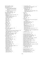
9.4.4 Six wheel vehicle with tandem rear axle
steering geometry (Fig. 9.28)
For any number of road wheels on a vehicle to
achieve true rolling when cornering, all projected
lines drawn through each wheel axis must intersect
at one common point on the inside track, this being
the instantaneous centre about which the vehicle
travels. In the case of a tandem rear axle arrange-
ment in which the axles are situated parallel to each
345
other, lines projected through the axles would
never meet and in theory true rolling cannot exist.
However, an approximate instantaneous centre for
the steered vehicle can be found by projecting a line
mid-way and parallel between both rear axles, this
being assumed to be the common axis of rotation
(Fig. 9.30). Extended lines passing through both
front wheel stub axles, if made to intersect at one
point somewhere along the common projected sin-
gle rear axle line, will then produce very near true
rolling condition as predicted by the Ackermann
principle.
Improvements in rear axle suspension design
have introduced some degree of roll steer which
minimizes tyre scrub on the tandem axle wheels.
This is achieved by the camber of the leaf springs
supporting the rear axles changing as the body rolls
so that both rear axles tend to skew in the plan view
so that the imaginary extended lines drawn through
both rear axles would eventually meet. Unfortu-
nately lines drawn through the front steered stub
axles and the rear skewed axles may not all meet at
one point. Nevertheless, they may almost merge so
that very near true rolling can occur for a large
proportion of the steering angle when the vehicle is
in motion. The remainder of the rear axle wheel
misalignment is absorbed by suspension spring
distortion, shackle joints or torque arm rubber
joints, and tyre compliance or as undesirable tyre
scrub.
9.4.5 Dual front axle steering
Operating large rigid trucks with heavy payloads
makes it necessary in addition to utilizing tandem
axles at the rear to have two axles in the front of the
vehicle which share out and support the load.
Both of the front axles are compelled to be steer
axles and therefore need to incorporate steering
linkage such as will produce true or near true
rolling when the vehicle is driven on a curved
track.
The advantages gained by using dual front steer-
ing axles as opposed to a single steer axle are as
follows:
Fig. 9.28 Six wheel tandem rear axle vehicle steering
geometry
Table 9.2 Lateral offset tables
Lateral offset of front wheels in relation to rear wheels
(Measurements in millimeters)
Wheelbase
mm
10
20
30
40
50
60
1800 4.0 7.5 11.5 15.0 19.0 23.0
2000 4.5 8.5 13.0 17.5 22.0 26.0
2200 5.0 10.0 15.0 20.0 24.5 30.0
2400 5.5 11.0 16.5 22.0 27.5 33.5
2600 6.0 12.0 18.5 24.5 30.5 37.0
2800 6.5 13.5 20.0 26.5 33.5 40.5
3000 7.0 14.5 22.0 29.0 36.5 44.0
3200 8.0 15.5 23.5 31.5 39.0 47.5
3400 8.5 17.0 25.0 33.5 42.0 51.0
3600 9.0 18.0 27.0 36.0 45.0 54.5
3800 9.5 19.0 28.5 38.5 48.0 58.0
(Measurements in inches)
Wheelbase 10
20
30
40
50
60
ft in
6 0 0.2 0.3 0.5 0.6 0.8 0.9
6 6 0.2 0.3 0.5 0.7 0.8 1.0
7 0 0.2 0.4 0.6 0.7 0.9 1.1
7 6 0.2 0.4 0.6 0.8 1.0 1.2
8 0 0.2 0.4 0.7 0.9 1.1 1.3
8 6 0.2 0.5 0.7 1.0 1.2 1.4
9 0 0.3 0.5 0.8 1.0 1.3 1.5
9 6 0.3 0.5 0.8 1.1 1.4 1.6
10 0 0.3 0.6 0.9 1.2 1.5 1.7
10 6 0.3 0.6 0.9 1.2 1.5 1.9
11 0 0.3 0.7 1.0 1.3 1.6 2.0
11 6 0.3 0.7 1.0 1.4 1.7 2.1
A negative ( À) value indicates front wheels offset to left
A positive ( ) value indicates front wheels offset to right
346
1 The static payload is reduced per axle so that
static and dynamic stresses imposed on each
axle assembly are considerably lessened.
2 Road wheel holding is improved with four
steered wheels as opposed to two, particularly
over rough ground.
3 Road wheel impact shocks and the subsequent
vibrations produced will be considerably
reduced as the suspension for both sets of wheels
share out the vertical movement of each axle.
4 Damage to one axle assembly or a puncture to
one of the tyres will not prevent the vehicle being
safely steered to a standstill.
5 Tyre wear rate is considerably reduced for dual
axle wheels compared to single axle arrange-
ments for similar payloads. Because the second
axle wheels have a smaller turning angle relative
to the foremost axle wheels, the tyre wear is
normally less with the second axle road wheels.
A major disadvantage with dual front axles is
that it is unlikely in practice that both instant-
aneous centres of the first and second stub axle turn-
ing circles will actually intersect at one point for all
angles of turn. Therefore tyre scrub may be excessive
for certain angles of steering wheel rotation.
Dual front axle steering geometry (Fig. 9.29)
When a pair of axles are used to support the front
half of a vehicle each of these axles must be steered
if the vehicle is to be able to negotiate a turning
circle.
For a dual front axle vehicle to be steered, the
Ackermann principle must apply to each of the
front axles. This means that each axle has two
wheels pivoted at each end of its beam. To enable
true rolling of the wheels to take place when the
vehicle is travelling along a curved track, lines
drawn through each of these four stub axles must
intersect at a common centre of rotation, some-
where along the extended line drawn between the
tandem rear axles (Fig. 9.29).
Because the wheelbase between the first front
axle is longer than the second front axle, relative
to the mid-tandem axle position, the turning angles
of both first front wheels will be greater than those
of the second front axle wheels. The correct angle
difference between the inner and outer wheels of
each axle is obtained with identical Ackermann
linkage settings, whereas the angle differential
between the first and second axles is formed by
the connecting rod ball joint coupling location on
both relay drop arms being at different distances
from their respective pivot point.
The dual steering linkage with power assistance
ram usually utilizes a pair of swing relay drop arms
bolted onto the chassis side member with their free
ends attached to each axle drag link (Fig. 9.30).
The input work done to operate the steering is
mainly supplied by the power cylinder which is
coupled by a ball joint to the steering gearbox
drop arm at the front and the power piston rod is
anchored through a ball joint and bracket to the
Fig. 9.29 Dual front axle steering Ackermann geometry
Fig. 9.30 Dual front axle steering linkage layout with
power assistance
347
chassis at the rear end. To transfer the driver's
input effort and power assistance effort to both
steer axles, a forward connecting rod links the
front end of the power cylinder to the first relay
drop arm. A second relay connecting rod then joins
both relay arms together.
A greater swivel movement of the first pair of
stub axles compared to the second is achieved (Fig.
9.31) by having the swing drop arm effective length
of the first relay AB shorter than the second relay
arm A
H
B
H
. Therefore the second relay arm push or
pull movement will be less than the input swing of
the first relay arm. As a result, the angular swing of
the first relay, Â 20
, will be less than for the
second relay arm angular displacement, Â
H
14
.
Dual front axle alignment checks using Dunlop
optical measurement equipment (Fig. 9.32(a±d))
1 Roll or drive forward. Check the toe-in or -out of
both pairs of front steering wheels and adjust
track rods if necessary (Fig. 9.32(a)).
2 Assemble mirror gauge stand with the mirror
positioned at right angles to the tubular stand.
Position the mirror gauge against a rear axle
wheel (preferably the nearest axle to the front)
with the mirror facing towards the front of the
vehicle (Fig. 9.32(b)).
3 Place the view box gauge stand on the floor in a
transverse position at least one metre in front of
the vehicle so that the view box faces the mirror
(Fig. 9.32(c)). Move the view box stand across until
the reflected image is centred in the view box with a
zero reading on the scale. Chalk mark the position
of the view box tripod legs on the ground.
4 Bring the mirror gauge stand forward to the first
steer axle wheel and place gauge prods against
wheel rim (Fig. 9.34(c)).
5 If both pairs of steer axle wheels are set parallel
(without toe-in or -out), set the pointer on the toe
angle scale to zero. Conversely, if both steer axles
have toe-in or -out settings, move the pointer on
the toe angle scale to read half the toe-in or -out
Fig. 9.31 Dual front axle steering interconnecting relay linkage principle
Fig. 9.32 Dual front axle wheel alignment procedure
348
figure, i.e. with a track toe angle of 30
H
set the
pointer to read 15
H
.
6 Look through the periscope tube and with an
assistant move the driver's steering wheel in the
cab until the hairline is central in the view box
(Fig. 9.32(c)). At the same time make sure that
the mirror gauge prods are still in contact with
the front wheel rim. The first front steer axle is
now aligned to the first rigid rear axle.
7 Move the mirror gauge from the first steer axle
wheel back to the second steer axle wheel and
position the prods firmly against the wheel rim
(Fig. 9.32(d)).
8 Look into the periscope. The hairline in the
view box should be centrally positioned with
the toe angle pointer still in the same position
as used when checking the first steer axle (Fig.
9.32(d)).
If the hairline is off-centre, the relay connecting
rod between the two relay idler arms should be
adjusted until the second steer axle alignment rela-
tive to the rear rigid axle and the first steer axle has
been corrected. Whilst carrying out any adjustment
to the track rods or relay connecting rod, the over-
all wheel alignment may have been disturbed.
Therefore a final check should be made by repeat-
ing all steps from 2 to 8.
9.4.6 Steer angle dependent four wheel steering
system (Honda)
This steer angle dependent four wheel steering sys-
tem provides dual steering characteristics enabling
same direction steer to take place for small steering
wheel angles. This then changes to opposite direc-
tion steer with increased steering wheel deviation
from the straight ahead position. Both of these
steer characteristics are explained as follows:
Opposite direction steer (Fig. 9.33) At low speed
and large steering wheel angles the rear wheels are
turned by a small amount in the opposite direction
to the front wheels to improve manoeuvrability
when parking (Fig. 9.32). In effect opposite direc-
tion steer reduces the car's turning circle but it does
have one drawback; the rear wheels tend to bear
against the side of the kerb. Generally there is
sufficient tyre sidewall distortion and suspension
compliance to accommodate the wheel movement
as it comes into contact with the kerb so that only
at very large steering wheel angles can opposite
direction steer becomes a serious problem.
Same direction steer (Fig. 9.33) At high speed and
small steering wheel angles the rear wheels are
turned a small amount in the same direction as
the front wheels to improve both steering response
and stability at speed (Fig. 9.33). This feature is
particularly effective when changing lanes on
motorways. Incorporating a same direction steer
to the rear wheels introduces an understeer char-
acteristic to the car because it counteracts the angu-
lar steering movement of the front wheels and
consequently produces a stabilizing influence in
the high speed handling of the car.
Front and rear road wheel response relative to the
steering wheel angular movement (Fig. 9.33) Mov-
ing the steering wheel approximately 120
from its
central position twists the front wheels 8
from the
Fig. 9.33 Front and rear wheel steer relationship to
driver's steering wheel angular movement
349
straight ahead position. Correspondingly, it moves
the eccentric shaft peg to its maximum horizontal
annular gear offset, this being equivalent to a maxi-
mum 1.5
same direction steer for the rear road
wheels (Fig. 9.33).
Increasing the steering wheel rotation to 232
turns the front wheels 15.6
from the straight
ahead position which brings the planetary peg
towards the top of the annular gear and in vertical
alignment with the gear's centre. This then cor-
responds to moving the rear wheels back to the
straight ahead position (Fig. 9.33).
Further rotation of the steering wheel from the
straight ahead position orbits the planetary gear
over the right hand side of the annular gear.
Accordingly the rear wheels steadily move to the
opposite direction steer condition up to a maxi-
mum of 5.3
when the driver's steering wheel has
been turned roughly 450
(Fig. 9.33).
Four wheel steer (FWS) layout (Fig. 9.34) The
steering system is comprised of a rack and pinion
front steering box and a rear epicyclic steering box
coupled together by a central drive shaft and a pair
of Hooke's universal end joints (Fig. 9.35). Both
front and rear wheels swivel on ball suspension
joints which are steered by split track rods actuat-
ing steering arms. The front road wheels are inter-
linked by a rack and transverse input movement to
the track rods is provided by the input pinion shaft
which is connected to the driver's steering wheel via
a split steering shaft and two universal joints. Steer-
ing wheel movement is relayed to the rear steering
box by way of the front steering rack which meshes
with an output pinion shaft. This movement of the
front rack causes the output pinion and centre
drive shaft to transmit motion to the rear steering
box. The rear steering box mechanism then con-
verts the angular input shaft motion to a transverse
linear movement. This is then conveyed to the rear
wheel swivels by the stroke rod and split track rods.
Rear steering box construction (Fig. 9.35) The
rear steering box is basically formed from an epi-
cyclic gear set consisting of a fixed internally
toothed annular ring gear in which a planetary
gear driven by an eccentric shaft revolves (Fig.
9.35). Motion is transferred from the input eccentric
shaft to the planetary gear through an offset peg
attached to a disc which is mounted centrally on
the eccentric shaft. Rotation of the input eccentric
shaft imparts movement to the planetary gear which
is forced to orbit around the inside of the annular
gear. At the same time, motion is conveyed to the
guide fork via a second peg mounted eccentrically
on the face of the planetary gear and a slider plate
which fits over the peg (Fig. 9.35). Since the slider
plate is located between the fork fingers, the rotation
of the planetary gear and peg causes the slider plate
to move in both a vertical and horizontal direction.
Due to the construction of the guide fork, the slider
plate is free to move vertically up and down but is
constrained in the horizontal direction so that the
stroke rod is compelled to move transversely to and
fro according to the angular position of the planet-
ary gear and peg.
Adopting this combined epicyclic gear set with
a slider fork mechanism enables a small same direc-
tion steer movement of the rear wheels to take
place for small deviation of the steering wheel
from the straight ahead position. The rear wheels
then progressively change from a same direction
steer movement into an opposite steer displace-
ment with larger steering angles.
The actual steering wheel movement at which
the rear wheels change over from the same direc-
Fig. 9.34 Four wheel steering (4WS) system
350
tion steer to the opposite direction steer and the
magnitude of the rear wheel turning angles relative
to both conditions are dependent upon the epi-
cyclic gear set gear ratio chosen.
Rear steering box operation (Fig. 9.36(a±e)) The
automatic correction of the rear road wheels from
a same direction steer to opposite direction steer
with increasing front road wheel turning angle and
vice versa is explained by Fig. 9.36(a±e).
Central position With the steering wheel in the
straight ahead position, the planetary gear sits at
the bottom of the annular gear with both eccentric
shaft and planetary pegs located at bottom dead
centre in the mid-position (Fig. 9.36(a)).
90
eccentric shaft peg rotation Rotating the
eccentric shaft through its first quadrant (0±90
)
in a chosen direction from the bottom dead centre
position compels the planetary gear to roll in an
anticlockwise direction up the left hand side of
the annular ring gear. This causes the planetary
peg and the stroke rod to be displaced slightly
to the left (Fig. 9.36(b)) and accordingly makes
the rear wheels move to a same direction steer
condition.
180
eccentric shaft peg rotation Rotating the
eccentric shaft through its second quadrant
(90±180
) causes the planetary gear to roll anti-
clockwise inside the annular gear so that it moves
with the eccentric peg to the highest position. At the
same time, the planetary peg orbits to the right
hand side of the annular gear centre line
(Fig. 9.36(c)) so that the rear road wheels turn to
the opposite direction steer condition.
270
eccentric shaft peg rotation Rotating the
eccentric shaft through a third quadrant (180±270
)
moves the planetary gears and the eccentric shaft peg
to the 270
position, causing the planetary peg to
orbit even more to the right hand side (Fig. 9.36(d)).
Consequently further opposite direction steer will be
provided.
360
eccentric shaft peg rotation Rotating
the eccentric shaft through a fourth quadrant
(270±360
) completes one revolution of the
eccentric shaft. It therefore brings the planetary
gear back to the base of the annular ring gear
with the eccentric shaft peg in its lowest position
(Fig. 9.36(e)). The planetary peg will have moved
back to the central position, but this time the peg is
in its highest position. The front to rear wheel
steering drive gearing is normally so arranged that
Fig. 9.35 Epicyclic rear steering box
351