Advanced Vehicle Technology Episode 2 Part 7 doc
Bạn đang xem bản rút gọn của tài liệu. Xem và tải ngay bản đầy đủ của tài liệu tại đây (390.06 KB, 20 trang )
movement ratios. A small input effort applied to
the end of a perpendicular lever fixed to the screw is
capable of moving a much larger load axially along
the screw provided that the nut is prevented from
rotating.
If the screw is prevented from moving longitu-
dinally and it revolves once within its nut, the nut
advances or retracts a distance equal to the axial
length of one complete spiral groove loop. This
distance is known as the thread pitch or lead (p).
The inclination of the spiral thread to the per-
pendicular of the screw axis is known as the helix
angle G. The smaller the helix angle the greater
the load the nut is able to displace in an axial
direction. This is contrasted by the reduced dis-
tance the nut moves forwards or backwards for
one complete revolution of the screw.
The engaged or meshing external and internal
spiral threads may be considered as a pair of infin-
itely long inclined planes (Fig. 9.3(a and b)). When
the nut is prevented from turning and the screw is
rotated, the inclined plane of the screw slides rela-
tive to that of the nut. Consequently, a continuous
wedge action takes place between the two members
in contact which compels the nut to move along the
screw.
Because of the comparatively large surface areas
in contact between the male and female threads and
the difficulty of maintaining an adequate supply of
lubricant between the rubbing faces, friction in this
mechanism is relatively high with the result that
mechanical efficiency is low and the rate of wear
is very high.
A major improvement in reducing the friction
force generated between the rubbing faces of the
threads has been to introduce a series of balls
(Fig. 9.4) which roll between the inclined planes
as the screw is rotated relatively to the nut.
The overall gear ratio is achieved in a screw and
nut steering gearbox in two stages. The first stage
occurs by the nut moving a pitch length for every
one complete revolution of the steering wheel. The
second stage takes place by converting the linear
movement of the nut back to an angular one via an
integral rocker lever and shaft. Motion is imparted
to the rocker lever and shaft by a stud attached to
the end of the rocker lever. This stud acts as a pivot
and engages the nut by means of a slot formed at
right angles to the nut axis.
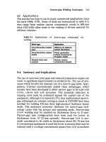
Fig. 9.3 (a and b) Principle of screw and nut steering gear
Fig. 9.4 Screw and nut recirculating ball low friction gear
mechanism
312
Forward and reverse efficiency The forward effi-
ciency of a steering gearbox may be defined as the
ratio of the output work produced at the drop arm
to move a given load to that of the input work done
at the steering wheel to achieve this movement.
i:e: Forward efficiency
Output work at drop arm
Input work at steering wheel
 100
Conversely the reverse efficiency of a steering
gearbox is defined as the ratio of the output work
produced at the steering wheel rim causing it to
rotate against a resisting force to that of the input
work done on the drop arm to produce this
movement.
i:e: Reverse efficiency
Output work at steering wheel
Input work at drop arm
 100
A high forward efficiency means that very little
energy is wasted within the steering gearbox in
overcoming friction so that for a minimum input
effort at the steering wheel rim a maximum output
torque at the drop arm shaft will be obtained.
A small amount of irreversibility is advanta-
geous in that it reduces the magnitude of any road
wheel oscillations which are transmitted back to
the steering mechanism. Therefore the vibrations
which do get through to the steering wheel are
severely damped.
However, a very low reverse efficiency is undesir-
able because it will prevent the self-righting action
of the kingpin inclination and castor angle straight-
ening out the front wheels after steering the vehicle
round a bend.
Relationship between the forward and reverse effi-
ciency and the helix angle (Figs 9.3, 9.4 and 9.5)
The forward efficiency of a screw and nut mechan-
ism may be best illustrated by considering the
inclined plane (Fig. 9.3(a)). Here the inclined
plane forms part of the thread spiral of the screw
and the block represents the small portion of the
nut. When the inclined plane (wedge) is rotated
anticlockwise (moves downwards) the block (nut)
is easily pushed against whatever load is imposed
on it. When the screw moves the nut the condition
is known as the forward efficiency.
In the second diagram (Fig. 9.3(b)) the block
(nut) is being pressed towards the right which in
turn forces the inclined plane to rotate clockwise
(move upward), but this is difficult because the
helix angle (wedge angle) is much too small when
the nut is made to move the screw. Thus when the
mechanism is operated in the reverse direction the
efficiency (reverse) is considerably lower than when
the screw is moving the nut. Only if the inclined
plane angle was to be increased beyond 40
would
the nut be easily able to rotate the screw.
The efficiency of a screw and nut mechanism will
vary with the helix angle (Fig. 9.5). It will be at a
maximum in the region of 40±50
for both forward
and reverse directions and fall to zero at the two
extremes of 0 and 90
(helix angle). If both forward
and reverse efficiency curves for a screw and nut
device were plotted together they would both look
similar but would appear to be out of phase by an
amount known as the friction factor.
Selecting a helix angle that gives the maximum
forward efficiency position (A) produces a very high
reverse efficiency (A
H
) and therefore would feed back
to the driver every twitch of the road wheels caused
by any irregularities on the road surface. Conse-
quently it is better to choose a smaller helix angle
which produces only a slight reduction in the for-
ward efficiency (B) but a relatively much larger
reduced reverse efficiency (B±B
H
). As a result this
will absorb and damp the majority of very small
vibrations generated by the tyres rolling over the
road contour as they are transmitted through the
steering linkage to the steering gearbox.
A typical value for the helix angle is about 30
which produces forward and reverse efficiencies of
about 55% and 30% without balls respectively. By
incorporating recirculating balls between the screw
and nut (Fig. 9.4) the forward and reverse efficien-
cies will rise to approximately 80% and 60%
respectively.
Fig. 9.5 Efficiency curves for a screw and nut
recirculating ball steering gear
313
Summary and forward and reverse efficiency The
efficiency of a screw and nut mechanism is rela-
tively high in the forward direction since the input
shaft screw thread inclined plane angle is small.
Therefore a very large wedge action takes place in
the forward direction. In the reverse direction, tak-
ing the input to be at the steering box drop arm
end, the nut threads are made to push against the
steering shaft screw threads, which in this sense
makes the inclined plane angle very large, thus
reducing the wedge advantage. Considerable axial
force on the nut is necessary to rotate the steering
shaft screw in the reverse direction, hence the
reverse efficiency of the screw and nut is much
lower than the forward efficiency.
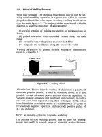
9.1.3 Cam and peg steering gearbox (Fig. 9.6)
With this type of steering box mechanism the con-
ventional screw is replaced by a cylindrical shaft
supported between two angular contact ball bear-
ings (Fig. 9.6). Generated onto its surface between
the bearings is a deep spiral groove, usually with
a variable pitch. The groove has a tapered side wall
profile which narrows towards the bottom.
Positioned half-way along the cam is an integral
rocker arm and shaft. Mounted at the free end of
the rocker arm is a conical peg which engages the
tapered sides of the groove. When the camshaft is
rotated by the steering wheel and shaft, one side of
the spiral groove will screw the peg axially forward
or backward, this depending upon the direction the
cam turns. As a result the rocker arm is forced to
pivot about its shaft axis and transfers a similar
angular motion to the drop arm which is attached
to the shaft's outer end.
To increase the mechanical advantage of the cam
and peg device when the steering is in the straight
ahead position, the spiral pitch is generated with
the minimum pitch in the mid-position. The pitch
progressively increases towards either end of the
cam to give more direct steering response at the
expense of increased steering effort as the steering
approaches full lock.
Preload adjustment of the ball races supporting
the cam is provided by changing the thickness of
shim between the end plate and housing. Spring
loaded oil seals are situated at both the drop arm
end of the rocker shaft and at the input end of the
camshaft.
Early low efficiency cam and peg steering boxes
had the peg pressed directly into a hole drilled in
the rocker arm, but to improve efficiency it is usual
Fig. 9.6 Cam and peg steering type gearbox
314
to support the peg with needle rollers assembled
inside an enlarged bore machined through the
rocker arm. For heavy duty applications, and
where size permits, the peg can be mounted in a
parallel roller race with a combined radial and
thrust ball race positioned at the opposite end to the
peg's tapered profile. An alternative high efficiency
heavy duty arrangement for supporting the peg uses
opposing taper roller bearings mounted directly
onto the rocker arm, which is shaped to form the
inner tracks of the bearings.
Cam and peg mechanisms have average forward
and reverse efficiencies for pegs that are fixed in
the rocker arm of 50% and 30% respectively, but
needle mounted pegs raise the forward efficiency
to 75% and the reverse to 50%.
To obtain the correct depth of peg to cam groove
engagement, a rocker shaft end play adjustment
screw is made to contact a ground portion of the
rocker shaft upper face.
The rocker shaft rotates in a bronze plain bear-
ing at the drop arm end and directly against the
bearing bore at the cam end. If higher efficiency is
required, the plain bush rocker shaft bearing can be
replaced by needle bearings which can raise the
efficiency roughly 3±5%.
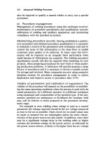
9.1.4 Worm and roller type steering gearbox
(Fig. 9.7)
This steering gear consists of an hourglass-shaped
worm (sometimes known as the cam) mounted
between opposing taper roller bearings, the outer
race of which is located in the end plate flange and
in a supporting sleeve at the input end of the worm
shaft (Fig. 9.7). Shims are provided between the
end plates and housing for adjusting the taper
roller bearing preload and for centralizing the
worm relative to the rocker shaft.
Engaging with the worm teeth is a roller follower
which may have two or three teeth. The roller
follower is carried on two sets of needle rollers
supported on a short steel pin which is located
between the fork arm forged integrally with the
rocker shaft.
In some designs the needle rollers are replaced by
ball races as these not only support radial loads but
also end thrust, thereby substantially reducing
frictional losses.
Fig. 9.7 Worm and roller type steering gearbox
315
The rocker shaft is supported on two plain
bushes; one located in the steering box and the
other in the top cover plate. End thrust in both
directions on the rocker shaft is taken by a shoul-
dered screw located in a machined mortise or
`T' slot at one end of the rocker shaft.
To adjust the depth of mesh of the worm and
roller (Fig. 9.7), move the steering wheel to the
mid-position (half the complete number of turns
of the steering wheel from lock to lock), screw in
the end thrust shouldered screw until all free move-
ment is taken up and finally tighten the lock nut
(offset distance being reduced).
Centralization of the cam in relation to the
rocker shaft roller is obtained when there is an
equal amount of backlash between the roller and
worm at a point half a turn of the steering wheel at
either side of the mid-position. Any adjustment
necessary is effected by the transference from one
end plate to the other of the same shims as those
used for the taper bearing preload (i.e. the thick-
ness of shim removed from one end is added to the
existing shims at the other).
The forward and reverse efficiencies of the worm
roller gear tend to be slightly lower than the cam
and peg type of gear (forward 73% and reverse
48%) but these efficiencies depend upon the design
to some extent. Higher efficiencies can be obtained
by incorporating a needle or taper roller bearing
between the rocker shaft and housing instead of the
usual plain bush type of bearing.
9.1.5 Recirculating ball nut and rocker lever
steering gearbox (Fig. 9.8)
Improvement in efficiency of the simple screw and
nut gear reduction is achieved with this design by
replacing the male and female screw thread by
semicircular grooves machined spirally onto the
input shaft and inside the bore of the half nut and
then lodging a ring of steel balls between the inter-
nal and external grooves within the nut assembly
(Fig. 9.8).
The portion of the shaft with the spiral groove is
known as the worm. It has a single start left hand
spiral for right hand drive steering and a right hand
spiral for left hand drive vehicles.
Fig. 9.8 Recirculating ball nut and rocker lever steering type gearbox
316
The worm shaft is supported between two sets of
ball races assembled at either end normally in an
aluminium housing. Steel shims sandwiched
between the detachable plate at the input end of
the shaft provide adjustment of the bearing pre-
load. Situated on the inside of the end plate is
a spring loaded lip seal which contacts the smooth
surface portion of the worm shaft.
Assembled to the worm is a half nut with a
detachable semicircular transfer tube secured to
the nut by a retainer and two bolts. The passage
formed by the grooves and transfer tube is fitted
with steel balls which are free to circulate when the
worm shaft is rotated.
The half nut has an extended tower made up of
a conical seat and a spigot pin. When assembled,
the conical seat engages with the bevel forks of the
rocker lever, whereas a roller on the nut spigot
engages a guide slot machined parallel to the
worm axis in the top cover plate. When the worm
shaft is rotated, the spigot roller engaged in its
elongated slot prevents the nut turning. Movement
of the nut along the worm will result in a similar
axial displacement for the spigot roller within its
slot.
End float of the rocker lever shaft is controlled
by a spring loaded plunger which presses the rocker
lever bevel forks against the conical seat of the half
nut.
The rocker lever shaft is supported directly in the
bore of the housing material at the worm end but
a bronze bush is incorporated in the housing at
the drop arm end of the shaft to provide adequate
support and to minimize wear. An oil seal is fitted
just inside the bore entrance of the rocker shaft
to retain the lubricant within the steering box
housing.
The worm shaft has parallel serrations for the
attachment of the steering shaft, whereas the
rocker shaft to drop arm joint is attached by a
serrated taper shank as this provides a more secure
attachment.
Forward and reverse efficiencies for this type of
recirculating ball and rocker lever gear is approxi-
mately 80% and 60% respectively.
9.1.6 Recirculating ball rack and sector steering
gearbox (Fig. 9.9)
To reduce friction the conventional screw and nut
threads are replaced by semicircular spiral grooves
(Fig. 9.9). These grooves are machined externally
around and along the cylindrically shaped shaft
which is known as the worm and a similar groove
is machined internally through the bore of the nut.
Fig. 9.9 Recirculating ball rack and sector steering gearbox
317
Engagement of the worm and nut is obtained by
lodging a series of steel balls between the two sets of
matching semicircular spiral grooves.
There are two separate ball circuits within the
ball nut, and when the steering wheel and worm
rotates, the balls roll in the grooves against the nut.
This causes the nut to move along the worm. Each
ball rotates one complete loop around the worm
after which it enters a ball return guide. The guide
deflects the balls away from the grooved passages
so that they move diagonally across the back of the
nut. They are then redirected again into the
grooved passages on the other side of the nut.
One outer face of the rectangular nut is machined in
the shape of teeth forming a gear rack. Motion from
the nut is transferred to the drop arm via a toothed
sector shaft which meshes with the rack teeth, so that
the linear movement of the nut is converted back to
a rotary motion by the sector and shaft.
An advantage of this type of steering gear is that
the rack and sector provides the drop arm with
a larger angular movement than most other types
of mechanisms which may be an essential feature
for some vehicle applications. Because of the
additional rack and sector second stage gear
reduction, the overall forward and reverse efficien-
cies are slightly lower than other recirculating ball
mechanisms. Typical values for forward and reverse
efficiencies would be 70% and 45% respectively.
9.2 The need for power assisted steering
(Figs 9.10 and 9.11)
With manual steering a reduction in input effort on
the steering wheel rim is achieved by lowering the
steering box gear ratio, but this has the side effect
of increasing the number of steering wheel turns
from lock so that manoeuvring of the steering will
take longer, and accordingly the vehicle's safe cor-
nering speed has to be reduced.
With the tendency for more weight to be put on
the front steering wheels of front wheel drive cars
and the utilization of radial ply tyres with greater
tyre width, larger static turning torques are required.
The driver's expectancy for faster driving and cor-
nering makes power assisted steering desirable and
in some cases essential if the driver's ability to
handle the vehicle is to match its performance.
Power assistance when incorporated on passen-
ger cars reduces the driver's input to something like
25±30% of the total work needed to manoeuvre it.
With heavy trucks the hydraulic power (servo)
assistance amounts to about 80±85% of the total
steering effort. Consequently, a more direct steer-
ing box gear reduction can be used to provide a
more precise steering response. The steering wheel
movement from lock to lock will then be reduced
approximately from 3 to 4 turns down to about
2 to 3 turns for manual and power assistance
steering arrangements respectively.
The amount of power assistance supplied to the
steering linkage to the effort put in by the driver is
normally restricted so that the driver experiences
the tyres' interaction with the ground under the
varying driving conditions (Fig. 9.10). As a result
there is sufficient resistance transmitted back to
the driver's steering wheel from the road wheels
to enable the driver to sense or feel the steering
input requirements needed effectively to steer the
vehicle.
Fig. 9.10 Typical relationship of tyre grip on various road
surfaces and the torque reaction on the driver's steering
wheel
Fig. 9.11 Comparison of manual steering with different
reduction gear ratio and power assisted steering
318
The effects of reducing the driver's input effort at
the steering wheel with different steering gear overall
gear ratios to overcome an output opposing resist-
ance at the steering box drop arm is shown in Fig.
9.11. Also plotted with these manual steering gear
ratios is a typical power assisted steering input effort
curve operating over a similar working load output
range. This power assisted effort curve shows that
for very low road wheel resistance roughly up to
1000 N at the drop arm, the input effort of 10 to
20 N is practically all manual. It is this initial manual
effort at the steering wheel which gives the driver his
sense of feel or awareness of changes in resistance to
steering under different road surface conditions,
such as whether the ground is slippery or not.
9.2.1 External direct coupled power assisted
steering power cylinder and control valve
Description of power assisted steering system
(Figs 9.12, 9.13 and 9.14) This directly coupled
power assisted system is hydraulic in operation.
The power assisted steering layout (Fig. 9.14) con-
sists of a moving power cylinder. Inside this cylin-
der is a double acting piston which is attached to
a ramrod anchored to the chassis by either rubber
bushes or a ball joint. One end of the power cylin-
der is joined to a spool control valve which is
supported by the steering box drop arm and the
other end of the power cylinder slides over the
stationary ramrod. When the system is used on a
commercial vehicle with a rigid front axle beam
(Fig. 9.12), the steering drag link is coupled to the
power cylinder and control valve by a ball joint. If
a car or van independent front suspension layout is
used (Fig. 9.13), the power cylinder forms a middle
moveable steering member with each end of the
split track rods attached by ball joints at either
end. The power source comes from a hydraulic
pump mounted on the engine, and driven by it a
pair of flexible hydraulic pipes connect the pump
and a fluid reservoir to the spool control valve
which is mounted at one end of the power cylinder
housing. A conventional steering box is used in the
system so that if the hydraulic power should fail the
steering can be manually operated.
With the removal of any steering wheel effort a
pre-compressed reaction spring built into the con-
trol valve (Fig. 9.14) holds the spool in the neutral
position in addition to a hydraulic pressure which
is directed onto reaction areas within the control
valve unit. Provided the steering effort is less than
that required to overcome the preload of the reac-
tion spring, the spool remains central and the fluid
is permitted to circulate from the pump through the
valve and back to the reservoir. Under these con-
ditions there will be no rise in hydraulic pressure
and the steering will be manually operated. Con-
sequently, the pump will be running light and
therefore will consume very little power.
When the steering effort at the driver's wheel is
greater than the preload stiffness of the reaction
spring, the spool valve will move slightly to one
side. This action partially traps fluid and prevents
it returning to the reservoir so that it now pres-
surizes one side or the other of the double acting
piston, thereby providing the power assistance
necessary to move the steering linkage. The more
the spool valve misaligns itself from the central
position the greater the restriction will be for the
fluid to return to the reservoir and the larger the
pressure build up will be on one side or the other of
the double acting piston to apply the extra steering
thrust to turn the steering road wheels.
Fig. 9.12 Steering box with external directly coupled
power assisted steering utilized with rigid axle front
suspension
Fig. 9.13 Steering box with external directly coupled
power assisted steering utilized with independent front
suspension
319
Operation of control valve and power piston
(Fig. 9.14)
Neutral position (Fig. 9.14(a)) With the valve
spool in the neutral position and no power assist-
ance being used, fluid from the pump passes freely
from the right hand supply port and annular
groove in the valve housing, across the spool
valve middle land to the return groove and port in
the valve housing, finally returning to the reservoir.
At the same time fluid passes from both the spool
grooves to passages leading to the left and right
hand power cylinder chambers which are sealed off
from each other by the double acting piston. Thus
whatever the position of the piston in the power
cylinder when the spool is in the central or neutral
position, there will be equal pressure on either side
of the double acting piston. Therefore the piston
will remain in the same relative position in the
cylinder until steering corrections alter the position
of the spool valve.
Right hand steering movement (Fig. 9.14(b)) If the
drop arm pushes the ball pin to the right, the spool
control edges 1 and 3 now overlap with the valve
housing lands formed by the annular grooves. The
fluid flows from the supply annular groove into the
right hand spool groove where it then passes along
passages to the right hand cylinder chamber where
the pressure is built up to expand the chamber.
The tendency for the right hand cylinder cham-
ber to expand forces fluid in the left hand contract-
ing cylinder chamber to transfer through passages
to the left hand spool groove. It then passes to the
valve housing return annular groove and port back
to the reservoir. Note that the ramrod itself
remains stationary, whereas the power cylinder is
the moving member which provides the steering
correction.
Left hand steering movement (Fig. 9.14(c)) Move-
ment of the drop arm to the left moves the spool
with it so that control edges 2 and 4 now overlap
with the adjacent valve housing lands formed by
the annular grooves machined in the bore. Fluid
flows from the supply annular groove in the valve
housing to the axial passage in the spool and is then
diverted radially to the valve body feed annular
groove and the spool left hand groove. Fluid con-
tinues to flow along the passage leading to the left
hand power cylinder chamber where it builds up
pressure. As a result the left hand chamber
expands, the right hand chamber contracts, fluid
is thus displaced from the reducing space back to
the right hand spool groove, it then flows out to the
valve housing return groove and port where finally
it is returned to the reservoir.
Progressive power assistance (Fig. 9.14(a)) While
the engine is running and therefore driving the
hydraulic power pump, fluid enters the reaction
chamber via the axial spool passage.
Before any spool movement can take place rela-
tive to the valve housing to activate the power
assistance, an input effort of sufficient magnitude
must be applied to the drop arm ball pin to com-
press the reaction spring and at the same time over-
come the opposing hydraulic pressure built up in
the reaction chamber. Both the reaction spring and
the fluid pressure are utilized to introduce a meas-
ure of resistance at the steering wheel in proportion
to the tyre to ground reaction resistance when the
steered road wheels are turned and power assist-
ance is used.
Progressive resistance at the steering wheel due
to the hydraulic pressure in the reaction chamber
can be explained in the following ways:
Right hand spool reaction (Fig. 9.14(b)) Consider
the drop arm ball pin initially moved to the right.
The reaction ring will also move over and slightly
compress the reaction spring. At the same time the
hydraulic pressure in the reaction chamber will
oppose this movement. This is because the pressure
acts between the area formed by the annular
shoulder in the valve chamber housing taking the
reaction spring thrust, and an equal projected area
acting on the reaction ring at the opposite end of
the chamber. The greater the hydraulic pressure the
larger the input effort must be to turn the steering
wheel so that the driver experiences a degree of feel
at the steering wheel in proportion to the resisting
forces generated between the tyre and road.
Left hand spool reaction (Fig. 9.14(c)) If the drop
arm and ball pin is moved to the left, the reaction
washer will move over in the same direction to
compress the reaction spring. Opposing this move-
ment is the hydraulic pressure which acts between
the reaction washer shoulder area formed by the
reduced diameter of the spool spindle and an equal
projected area of the reaction ring situated at the
opposite end. If the steering wheel effort is
removed, the hydraulic pressure in the reaction
320
Fig. 9.14 External directly coupled power assisted steering
321
chamber will react between the reaction ring, the
reaction washer housing and spool shoulders, and
thereby attempt to move the spool back to its
original central or neutral position.
Correction for the variation in cross-section areas on
opposite side of the power piston (Fig. 9.14(b and
c)) To counteract the reduction in effective area
on the ramrod side of the double acting piston, the
annular shoulder area of the spool (Fig. 9.14(b)) is
made slightly larger than the reaction ring annular
shoulder area (Fig. 9.14(c)) machined in the reac-
tion chamber. Consequently, a greater opposing
hydraulic reaction will be created when turning
the steering to the left to oppose the full cross-
sectional area of the power piston compared to
the situation when the steering is turned to the
right and a reduced power piston cross-sectional
area due to the ram is exposed to the hydraulic
pressure in the power cylinder. In this way a
balanced self-centralizing response is obtained in
whatever position the road steering wheels may be
positioned.
9.2.2 Rack and pinion power assisted steering
gear power cylinder and control valve
Rack and pinion gear (Fig. 9.15) This power
assisted steering system is comprised of a rack and
pinion gear with double acting power (servo) piston
mounted on the rack and a rotary valve coaxial with
the extended pinion shaft (Fig. 9.15).
Helical teeth are cut on the 3% nickel, 1% chro-
mium case hardened steel pinion shaft, they mesh
with straight cut teeth on a 0.4% carbon manga-
nese silicon steel rack which is induction hardened.
To accommodate these gears, the axis of the pinion
is inclined at 76
to that of the rack.
Description of rotary control valve (Fig. 9.16(a, b
and c)) The three major components of the rotary
type control valve are the rotor shaft, the torsion
bar and the valve sleeve (Fig. 9.16(a)).
Slots are milled longitudinally on the periphery of
the rotor shaft (Fig. 9.16(b)) and on the inner sur-
face of the valve sleeve of which the rotor is
assembled and in which it is free to rotate. The sleeve
is rotated by the pinion gear shaft. Limited rotation
of the rotor shaft, relative to the pinion gear, occurs
when the torsion bar that connects the rotor shaft to
the pinion shaft is angularly deflected. Hence when
steering effort is applied, the torsion bar twists and
the slots on the rotor move relative to those in the
sleeve to allow fluid to pass to one side of the double
acting piston which operates inside the power cylin-
der. The direction of rotation of the rotor relative to
the sleeve determines which side of the double acting
piston the fluid will act.
The rotor shaft of the valve forms part of the
0.5% carbon steel rotor shaft and is connected by a
torsion bar to the pinion shaft. The outer case-
hardened 0.15% carbon steel sleeve which is coaxial
with the rotor floats on the ground surface of the
rotor shaft, there being a diametrical clearance of
0.004 to 0.012 mm between the rotor and sleeve.
The sleeve is connected by a steel trim pin screw to
the pinion shaft. This pin, the threaded end of
which is in a tapped radial hole in the pinion
shaft, has a spherical head that fits with no clear-
ance in a radial hole drilled in the sleeve at the
pinion end. The axis of the head of this pin is
eccentric to that of the threaded shank. Hence,
when the pinion shaft and rotor shaft have been
locked in the central position of rotation, the cor-
rect angular position of the sleeve, relative to that
of the rotor, can be set by rotating the pin. This
permits the valve assembly to be trimmed, so that
the division of fluid flow between rotor and sleeve
slot edges is balanced. The amount of opening
between the rotor and sleeve control slots is equal
to the angular deflection of the torsion bar. Four
square section Teflon seals are assembled into annu-
lar grooves in the periphery of the sleeve. Between
these seals are three wider annular grooves, again on
the periphery of the sleeve, from which fluid enters
or leaves the valve assembly.
Rotor shaft to pinion shaft coupling (Fig. 9.16(a))
Splines at one end of the rotor shaft register in an
internally splined recess in the pinion shaft. The
width of the splines is such that the torsion bar can
twist a total of seven degrees before the splines
Fig. 9.15 Integral rack and pinion power assisted
steering utilized with independent front suspension
322
contact one another. Manual steering effort is trans-
ferred from the rotor shaft through the 1% chro-
mium-molybdenum-steel torsion bar, which has an
approximate waist diameter of 5 mm, to the pinion
shaft. The splined coupling between these two mem-
bers ensures that, in the event of failure of the power
assistance, the steering gear can be operated manu-
ally without overstressing the torsion bar.
Rotor and sleeve longitudinal and annular grooves
(Fig. 9.16(b)) Six equally spaced longitudinal
slots are milled on the circumference of the rotor.
Three of the rotor slots are longer than the other
three and these two lengths are disposed alternately
around the rotor periphery. There are also six
matching equally spaced groove slots with closed-
off ends in the bore of the valve sleeve. The angular
relationship of these two sets of slots controls the
flow of fluid from the pump to the power cylinder
and from the cylinder to the reservoir.
The positioning of the ports and annular grooves
around the valve sleeve are now considered from
the pinion end of the rotor shaft.
The first valve port feeds or returns fluid from the left
hand side of the power cylinder, the second port delivers
fluid from the pump, the third port feeds or returns fluid
from the right hand side of the power cylinder and the
fourth port acts as the return passage to the reservoir.
Each of the first three ports (counting from the
left) communicates with corresponding annular
grooves in the outer periphery of the sleeve, while
the fourth port, through which fluid is returned to
the reservoir, communicates with an annular space
between the right hand end of the valve housing
and the end of the sleeve.
Radial holes in the central sleeve groove connect
the pump pressurized fluid to the short supply slots
on the periphery of the rotor shaft. The sleeve
grooves on either side are connected through
small radial holes to the three longer slots on the
rotor surface. These longer slots provide a return
passage to the annular space on the right of the
valve which then leads back to the reservoir.
Whenever the pump is operating, fluid passes
through the delivery port in the sleeve and is then
transferred to the three short rotor slots. Thereafter
the fluid either passes directly to the longer slots,
and hence to the return port, or flows through one
feed and return port going to the power cylinder,
while fluid from the other end of the cylinder is
returned through the longer slots to the reservoir.
Torsion bar stiffness (Fig. 9.16(a)) When torque is
applied at the steering wheel, the grip of the tyres
on the road causes the torsion bar to twist. Relative
movement between the rotor shaft and sleeve
upsets the balanced flow of fluid and pressure at
the rotary control valve going to both sides of the
power piston. Therefore the deflection rate of the
torsion bar is important in determining the torque
required to steer the vehicle. To transmit the
desired input torque from the steering wheel and
rotor shaft to the pinion shaft, a standard 108 mm
long torsion bar is used. Its diameter and stiffness
are 5.2 mm and 1.273 N/deg and the actual dia-
meter of the torsion bar can be changed to suit
the handling requirements of the vehicle.
Rotor slot edge control (Fig. 9.16(b)) If the valve
rotor and sleeve slot control edges were sharp as
shown in the end view (Fig. 9.16(b)), the area
through which the fluid flowed would vary directly
with the deflection of the torsion bar, and hence the
applied torque. Unfortunately, the relationship
between pressure build-up and effective valve flow
area is one in which the pressure varies inversely as
the square of the valve opening area. This does not
provide the driver with a sensitive feel at the steer-
ing wheel rim. The matching of the pressure build-
up, and hence valve opening area, relative to the
driver's input effort at the steering wheel rim has
been modified from the simple sharp edge slots on
the rotor, to contoured stepped edges (Fig. 9.16(b))
which provide a logarithmic change of area so that
the increase of pressure with rim effort is linear.
This linear relationship is retained up to 28 bar
which is the limit for driving a large car under all
road conditions. Above 28 bar the rise of pressure
with applied steering wheel torque is considerably
steepened to ensure that parking efforts are kept to a
minimum. The relationship between the angular dis-
placement of the rotary valve and the hydraulic
pressure applied to one side of the power cylinder
piston is shown in Fig. 9.17.
An effort of less than 2.5 N at the rim of the
steering wheel is sufficient to initiate a hydraulic
pressure differential across the double acting power
piston. During manoeuvres at very low speeds when
parking, a manual effort of about 16 N is required.
When the car is stationary on a dry road, an effort of
22 N is sufficient to move the steering from the
straight ahead position to full lock position.
Operation of the rotary control valve and power
piston
Neutral position (Fig. 9.16(a)) With no steering
effort being applied when driving along a straight
323
Fig. 9.16 (a±d) Rack and pinion power assisted steering with rotary control valve
324
track, the longitudinal lands formed by the slots
milled on the rotor periphery angularly align with
the internal sleeve slots so that equal space exists
between the edges of adjacent rotor and sleeve
slots.
Fluid therefore flows from the pump to the deliv-
ery port into the short slots in the rotor. Some fluid
then passes to the feed/return slots in the sleeve and
out to the ports communicating with either side of
the power cylinder. The majority of the fluid will
pass between the edges of both the rotor and sleeve
slots to the rotor long slots where it then flows out
through the return port back to the reservoir.
Because fluid is permitted to circulate from the
pump to the reservoir via the control valve, there
is no pressure build-up across the power piston,
hence the steering remains in the neutral position.
Anticlockwise rotation of the steering wheel
(Fig. 9.16(b)) Rotating the steering wheel anti-
clockwise twists the rotor shaft and torsion bar so
that the leading edges of the rotor lands align with
corresponding lands on the sleeve, thereby block-
ing off the original fluid exit passage. Fluid now
flows from the pump delivery port to the short slots
on the rotor. It then passes between the trailing
rotor and sleeve edges, through to the sleeve slots
and from there to the left hand side of the power
cylinder via the feed/return pipe so that the pres-
sure on this side of the piston rises. At the same
time fluid will be displaced from the right hand
cylinder end passing through to the sleeve slots
Fig. 9.16 contd
Fig. 9.17 Relationship of fluid pressure delivered to the
power cylinder from the control valve and the angular
deflection of the control valve and torsion bar
325
via the right hand feed/return pipe and port. The
flow of fluid continues, passing between the trailing
land edges of the rotor and sleeve to the long rotor
slots and out through the return pipe back to the
reservoir. Thus a pressure difference is established
across the double acting piston, to provide power
assistance.
Clockwise rotation of the steering wheel
(Fig. 9.16(c)) Rotating the steering wheel clock-
wise angularly deflects the rotor so that the leading
edges of the rotor lands overlap with corresponding
internal lands on the sleeve. Fluid now flows from
the pump delivery port into the short rotor slots and
out to the right hand feed/return port to the power
cylinder via the gap created between the trailing
edges of the rotor and sleeve lands. Pressurizing
the right hand side of the power cylinder pushes
fluid out from the left hand side of the cylinder,
through the feed/return pipe and port into the sleeve
slots, through the enlarged gap created between the
trailing rotor and sleeve edges and into the long
rotor slots. It is then discharged through the return
port and pipe back to the reservoir.
Progressive power assistance (Fig. 9.16(b and c))
When the steering wheel is turned left or right,
that is, anticlockwise or clockwise, the rotor shaft
which is rigidly attached to the steering column
shaft rotates a similar amount. A rotary movement
is also imparted through the torsion bar to the
pinion shaft and the valve sleeve as these members
are locked together. However, due to the tyre to
ground resistance, the torsion bar will twist slightly
so that the rotation of the pinion and sleeve will be
less than that of the rotor input shaft. The greater
the road wheel resistance opposing the turning of
the front wheel, the more the torsion bar will twist,
and therefore the greater the misalignment of the
rotor and sleeve slots will be. As a result, the gap
between the leading edges of both sets of slots will
become larger, with a corresponding increase in
fluid pressure entering the active side of the power
cylinder.
As the steering manoeuvres are completed, the
initially smaller sleeve angular movement catches
up with the rotor movement because either the
road wheel resistance has been overcome or steer-
ing wheel turning effort has been reduced. Con-
sequently, the reduced torque now acting on the
steering column shaft enables the torsion bar to
unwind (i.e. straighten out). This causes the
power assistance to be reduced in accordance with
the realignment or centralization of the rotor slots
relative to the sleeve lands.
9.2.3 Integral power assisted steering gear power
cylinder and control valve
Description of steering gear and hydraulic control
valve (Figs 9.18 and 9.19) The integral power
assisted steering gearbox can be used for both
rigid front axle and independent front suspension
(Fig. 9.18) layouts.
The rack and sector recirculating ball steering
gear, power cylinder and hydraulic control valves
are combined and share a common housing (Fig.
9.19(a)). The power piston in this arrangement not
only transforms hydraulic pressure into force to
assist the manual input effort but it has two other
functions:
1 it has a rack machined on one side which meshes
with the sector,
2 it has a threaded axial bore which meshes via a
series of recirculating balls with the input worm
shaft.
The input end of the worm shaft, known as the
worm head, houses two shuttle valve pistons which
have their axes at right angles to the worm shaft.
Since they are assembled within the worm head
they rotate with it.
Drive is transferred from the hollow input shaft
to the worm shaft through a torsion bar. Move-
ment of the shuttle valves relative to the worm shaft
which houses the valves is obtained by the hollow
double pronged input shaft. Each prong engages
with a transverse hole situated mid-way between
the shuttle valve ends.
Fig. 9.18 Integral steering gearbox and power assisted
steering utilized with independent front suspension
326
Exit groove
Intake groove
Delivery groove
Return passage
Torsion bar
Reservoi
r
Pump
Torsion bar
Double pronged
input shaft
Shuttle valve body
Worm head
Worm
Sector and shaft
Worm head
Return groove
Return grove
land
Shuttle valve
piston
Recirculating balls
Piston and nut
Return passage
closed
Return passage
open
Intake passage
closed
Intake passage
open
(b) Turning left
anticlockwise
(a) Neutral position
Fig. 9.19 (a±c) Integral power assisted steering gear power cylinder and control valve
327
When the steering wheel is turned, the tyre to
ground reaction on the front road wheels causes the
torsion bar to twist according to the torque applied
on the steering column shaft. Therefore the relative
angular movement of the worm shaft to that of the
input shaft increases in proportion to the input
torque at the steering wheel, so that the shuttle
valves will both be displaced an equal amount
from the mid-neutral position. As soon as the steer-
ing wheel effort is released, the elastic torsion bar
ensures that the two shuttle valves return to the
neutral or mid position. The function of these shut-
tle valves is to transfer fluid under pressure, in
accordance to the steering input torque, from
the pump delivery port to one or other end of the
integral power cylinder whilst fluid from the
opposite end of the cylinder is released and
returned to the reservoir.
Operation of control valve and power piston
Neutral position (Fig. 9.19(a)) Fluid from the
pump flows into and around an annular chamber
surrounding the worm head in a plane similar to
that of the shuttle valves where it acts on the
exposed end faces of the shuttle valve pistons.
With the shuttle valves in the neutral position,
fluid moves through the intake passages on the
right hand end of the shuttle valve pistons, to the
two annular grooves on the periphery of the worm
head. Fluid then passes from the worm head annu-
lar grooves to the left hand side of the power piston
(c) Turning right
clockwise
Return passage
open
Return passage
closed
Intake passage
open
Intake passage
closed
Double
pronged
input
shaft
Torsion
bar
(One of two)
Shuttle
valve
piston
Fig. 9.19 contd
328
via the horizontal long passage and sector cham-
ber, and to the right hand piston face directly by
way of the short passage. From the worm head
grooves fluid will also flow into the shuttle valve
return grooves, over each return groove land which
is aligned with the exit groove, to the middle
waisted region of the shuttle valve and into the
torsion bar and input shaft chamber. Finally fluid
moves out from the return pipe back to the pump
reservoir.
Turning left (anticlockwise rotation) (Fig. 9.19(b))
An anticlockwise rotation of the steering wheel
against the front wheel to ground opposing resist-
ance distorts the torsion bar as input torque is
transferred to the worm shaft via the torsion bar.
The twisting of the torsion bar means that the
worm shaft also rotates anticlockwise, but its angu-
lar movement will be less than the input shaft dis-
placement. As a result, the prongs of the input shaft
shift the upper and lower shuttle valves to the left
and right respectively. Accordingly this movement
closes both the intake and return passages of the
upper shuttle valve and at the same time opens
both the intake and return passages of the lower
shuttle valve.
Fluid can now flow from the pump into the worm
head annular space made in the outer housing. It
then passes from the lower shuttle valve intake to the
right hand worm head annular groove. The transfer
of fluid is complete when it enters the left hand
power cylinder via the sector shaft. The amount of
power assistance is a function of the pressure build-
up against the left side of the piston, which corre-
sponds to the extent of the shuttle valve intake pas-
sage opening caused by the relative angular
movements of both the input shaft and worm shaft.
Movement of the power piston to the right dis-
places fluid from the right hand side of the power
cylinder, where it flows via the worm head annular
groove to the lower shuttle valve return passage to
the central torsion bar and input shaft chamber.
It then flows back to the reservoir via the flexible
return pipe.
Turning right (clockwise rotation) (Fig. 9.19(c))
Rotating the steering wheel in a clockwise direction
applies a torque via the torsion bar to the worm
in proportion to the tyre to ground reaction and
the input effort. Due to the applied torque, the
torsion bar twists so that the angular movement
of the worm shaft lags behind the input shaft
displacement. Therefore the pronged input will
rotate clockwise to the worm head.
With a clockwise movement of the input shaft
relative to the worm head, the upper shuttle valve
piston moves to the right and the lower shuttle
valve piston moves to the left. Consequently, the
upper shuttle valve opens both the intake and
return passages but the lower shuttle valve closes
both the intake and return passages.
Under these conditions fluid flows from the
pump to the annular space around the worm head
in the plane of the shuttle valves. It then enters the
upper valve intake, fills the annular valve space and
passes around the left hand worm head groove.
Finally, fluid flows through the short horizontal
passage into the right hand side of the power cylin-
der where, in proportion to the pressure build-up, it
forces the piston to the left. Accordingly the mesh-
ing rack and sector teeth compel the sector shaft to
rotate anticlockwise.
At the same time as the fluid expands the right
hand side of the power cylinder, the left hand side
of the power cylinder will contract so that fluid will
be displaced through the long horizontal passage to
the worm head right hand annular groove. Fluid
then flows back to the reservoir via the upper shut-
tle valve return groove and land, through to the
torsion bar and input shaft chamber and finally
back to the reservoir.
9.2.4 Power assisted steering lock limiters
(Fig. 9.20(a and b))
Steering lock limiters are provided on power
assisted steering employed on heavy duty vehicles
to prevent excessive strain being imposed on the
steering linkage, the front axle beam and stub axles
and the supporting springs when steering full lock
is approached. It also protects the hydraulic com-
ponents such as the pump and the power cylinder
assembly from very high peak pressures which
could cause damage to piston and valve seals.
Power assisted steering long stem conical valve lock
limiter The lock limiters consist of a pair of con-
ical valves with extended probe stems located in the
sector shaft end cover (Fig. 9.20(a and b)). Each
valve is made to operate when the angular move-
ment of the sector shaft approaches either steering
lock, at which point a cam profile machined on the
end of the sector shaft pushes open one or other of
the limiting valves. Opening one of the limiter
valves releases the hydraulic pressure in the power
cylinder end which is supplying the assistance; the
329
Piston and nut
Left hand
valve open
Right hand
valve closed
Reservoir
ands
pump
Pressure
relief
valve
Flow
control
valve
Input
hollow
shaft
Torsion
bar
Sector
gear
Sector
shaft
Cam
profile
Conical
valve
and
profile
stem
(a) Turning left
anticlockwise
Left hand
closed
Right hand
valve open
(b) Turning right
clockwise
Fig. 9.20 (a and b) Power assisted steering long stem conical valve lock limiter
330
excess fluid is then permitted to flow back to the
reservoir via the control housing.
Turning left (anticlockwise steering rotation)
(Fig. 9.20(a)) Rotation of the input shaft anti-
clockwise applies both manual and hydraulic effort
onto the combined power piston and nut of the
steering box so that it moves to the right within
the cylinder. Just before the steering reaches full
lock, one of the sector cam faces contacts the cor-
responding valve stem and pushes the conical valve
off its seat. Pressurized fluid will immediately
escape past the open valve through to the return
chamber in the control valve housing, where it
flows back to the reservoir. Therefore, any further
rotation of the sector shaft will be entirely achieved
by a considerable rise in manual effort at the steer-
ing wheel, this being a warning to the driver that
the steering has reached maximum lock.
Turning right (clockwise steering rotation)
(Fig. 9.20(b)) Rotation of the steering box input
shaft clockwise screws the worm out from the piston
and nut and actuates the control valve so that
hydraulic pressure builds up on the right hand end
of the piston. As the sector shaft rotation approaches
maximum lock, the sector cam meets the valve stem,
presses open the valve against the valve return spring
tension and causes the hydraulic pressure in the right
hand cylinder chamber to drop. The excess fluid will
now flow back to the reservoir via the right hand end
annular chamber in the control valve housing. The
driver will immediately experience a considerable
increase in manual effort at the steering wheel, indi-
cating that the road wheels have been rotated to near
enough maximum lock.
Power assisted steering double ball valve lock
limiter This lock limiter consists of a simple dou-
ble ball valve located in the blank end of the inte-
gral piston and nut. To control the stroke of the
piston an adjustable stop pin is mounted in the
enclosed end of the power cylinder housing, while
the right hand piston movement is limited by the
stop pin mounted in the end of the worm shaft.
Turning left (anticlockwise steering rotation)
(Fig. 9.21(a)) Rotation of the steering input
shaft anticlockwise causes both manual and
hydraulic effort to act on the combined power
piston and nut, moving it towards the right. As
the steering lock movement is increased, the piston
approaches the end of its stroke until the right hand
ball valve contacts the worm shaft stop pin, thereby
forcing the ball off its seat. The hydraulic pressure
existing on the left side of the piston, which has
already opened the left hand side ball valve, is
immediately permitted to escape through the clear-
ance formed between the internal bore of the nut
and the worm shaft. Fluid will now flow along the
return passage leading to the control reaction valve
and from there it will be returned to the reservoir.
The release of the fluid pressure on the right side of
the piston therefore prevents any further hydraulic
power assistance and any further steering wheel
rotation will be entirely manual.
Turning right (clockwise steering rotation)
(Fig. 9.21(b)) Rotation of the steering box input
shaft clockwise screws the worm out from the pis-
ton and nut. This shifts the shuttle valve pistons so
that the hydraulic pressure rises on the right hand
end of the piston. Towards the end of the left hand
stroke of the piston, the ball valve facing the blind
end of the cylinder contacts the adjustable stop pin.
Hydraulic pressure will now force the fluid from
the high pressure end chamber to pass between the
worm and the bore of the nut to open the right
hand ball valve and to escape through the left hand
ball valve into the sector gear chamber. The fluid
then continues to flow along the return passage
going to the control reaction valve and from there
it is returned to the reservoir. The circulation of
fluid from the pump through the piston and back
to the reservoir prevents further pressure build-up so
that the steering gearbox will only operate in the
manual mode. Hence the driver is made aware that
the road wheels have been turned to their safe full
lock limit.
9.2.5 Roller type hydraulic pump
(Fig. 9.22(a and b))
The components of this pump (Fig. 9.22 (a and b))
consist of the stationary casing, cam ring and the
flow and pressure control valve. The moving parts
comprise of a rotor carrier mounted on the drive
shaft and six rollers which lodge between taper
slots machined around the rotor blank. The drive
shaft itself is supported in two lead-bronze bushes,
one of which is held in the body and the other in the
end cover. A ball bearing at the drive end of the
shaft takes the load if it is belt and pulley driven.
The rotor carrier is made from silicon manganese
steel which is heat treated to a moderate hardness.
331