Advanced Vehicle Technology Episode 1 Part 3 ppt
Bạn đang xem bản rút gọn của tài liệu. Xem và tải ngay bản đầy đủ của tài liệu tại đây (354.06 KB, 20 trang )
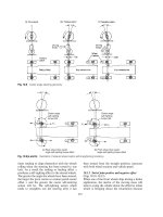
the tractor unit, just sufficiently back to clear the
rear tractor road wheels when the trailer is coupled
and the combination is being manoeuvred
(Fig. 1.28(a)). To provide additional support for
the legs, bracing stays are attached between the legs
and from the legs diagonally to the chassis cross-
member (Fig. 1.28(b)).
The legs consist of inner and outer high tensile
steel tubes of square section. A jackscrew with a
bevel wheel attached at its top end supported by the
outer leg horizontal plate in a bronze bush bearing.
The jawscrew fits into a nut which is mounted at
the top of the inner leg and a taper roller bearing
race is placed underneath the outer leg horizontal
support plate and the upper part of the jackscrew
to minimize friction when the screw is rotated (Fig.
1.28(b)). The bottom ends of the inner legs may
support either twin wheels, which enable the trailer
to be manoeuvred, or simply flat feet. The latter are
able to spread the load and so permit greater load
capacity.
To extend or retract the inner legs, a winding
handle is attached to either the low or high speed
shaft protruding from the side of the gearbox. The
upper high speed shaft supports a bevel pinion
which meshes with a vertically mounted bevel
wheel forming part of the jackscrew.
Rotating the upper shaft imparts motion directly
to the jackscrew through the bevel gears. If greater
leverage is required to raise or lower the front of the
trailer, the lower shaft is engaged and rotated.
This provides a gear reduction through a com-
pound gear train to the upper shaft which then
drives the bevel pinion and wheel and hence the
jackscrew.
1.6 Automatic chassis lubrication system
1.6.1 The need for automatic lubrication system
(Fig. 1.29)
Owing to the heavy loads they carry commercial
vehicles still prefer to use metal to metal joints which
are externally lubricated. Such joints are kingpins
and bushes, shackle pins and bushes, steering ball
joints, fifth wheel coupling, parking brake linkage
etc. (Fig. 1.29). These joints require lubricating in
proportion to the amount of relative movement and
the loads exerted. If lubrication is to be effective in
reducing wear between the moving parts, fresh oil
must be pumped between the joints frequently. This
can best be achieved by incorporating an automatic
lubrication system which pumps oil to the bearing's
surfaces in accordance to the distance travelled by
the vehicle.
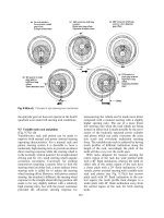
1.6.2 Description of airdromic automatic chassis
lubrication system (Fig. 1.30)
This lubrication system comprises four major com-
ponents; a combined pump assembly, a power unit,
an oil unloader valve and an air control unit.
Pump assembly (Fig. 1.30) The pump assembly
consists of a circular housing containing a ratchet
operated drive (cam) shaft upon which are
mounted one, two or three single lobe cams (only
one cam shown). Each cam operates a row of 20
pumping units disposed radially around the pump
casing, the units being connected to the chassis
bearings by nylon tubing.
Power unit (Fig. 1.30) This unit comprises a
cylinder and spring-loaded air operated piston
which is mounted on the front face of the pump
assembly housing, the piston rod being connected
indirectly to the drive shaft ratchet wheel by way of
a ratchet housing and pawl.
Oil unloader valve (Fig. 1.30) This consists of a
shuttle valve mounted on the front of the pump
assembly housing. The oil unloader valve allows air
pressure to flow to the power unit for the power
stroke. During the exhaust stroke, however, when
air flow is reversed and the shuttle valve is lifted
from its seat, any oil in the line between the power
unit and the oil unloader valve is then discharged to
atmosphere.
Fig. 1.27 Ball and socket caravan/trailer towing
attachment
32
Fig. 1.28 (a and b) Semi-trailer landing gear
33
Air control unit (Fig. 1.30) This unit is mounted
on the gearbox and is driven via the speedometer
take-off point. It consists of a worm and wheel drive
which operates an air proportioning control
unit. This air proportioning unit is operated by a
single lift face cam which actuates two poppet
valves, one controlling air supply to the power
unit, the other controlling the exhaust air from the
power unit.
1.6.3 Operation of airdromic automatic chassis
lubrication system (Fig. 1.30)
Air from the air brake auxiliary reservoir passes by
way of the safety valve to the air control (propor-
tioning) unit inlet valve. Whilst the inlet valve is
held open by the continuously rotating face cam
lobe, air pressure is supplied via the oil unloader
valve to the power unit attached to the multipump
assembly housing. The power unit cylinder is sup-
ported by a pivot to the pump assembly casing,
whilst the piston is linked to the ratchet and pawl
housing. Because the pawl meshes with one of the
ratchet teeth and the ratchet wheel forms part of
the camshaft, air pressure in the power cylinder will
partially rotate both the ratchet and pawl housing
and the camshaft clockwise. The cam (or cams) are
in contact with one or more pump unit, and so each
partial rotation contributes to a proportion of the
jerk plunger and barrel pumping cycle of each unit
(Fig. 1.30).
As the control unit face cam continues to rotate,
the inlet poppet inlet valve is closed and the exhaust
poppet valve opens. Compressed air in the air con-
trol unit and above the oil control shuttle valve will
now escape through the air control unit exhaust
port to the atmosphere. Consequently the com-
pressed air underneath the oil unloader shuttle
valve will be able to lift it and any trapped air and
oil in the power cylinder will now be released via
the hole under the exhaust port. The power unit
piston will be returned to its innermost position by
the spring and in doing so will rotate the ratchet
and pawl housing anti-clockwise. The pawl is thus
Fig. 1.29 Tractor unit automatic lubrication system
34
Fig. 1.30 Airdromic automatic chassis lubrication system
35
able to slip over one or more of the ratchet teeth to
take up a new position. The net result of the power
cylinder being charged and discharged with com-
pressed air is a slow but progressive rotation of the
camshaft (Fig. 1.30).
A typical worm drive shaft to distance travelled
relationship is 500 revolutions per 1 km. For 900
worm drive shaft revolutions the pumping cam
revolves once. Therefore, every chassis lubrication
point will receive one shot of lubricant in this
distance.
When the individual lubrication pump unit's
primary plunger is in its outermost position, oil
surrounding the barrel will enter the inlet port,
filling the space between the two plungers. As the
cam rotates and the lobe lifts the primary plunger,
it cuts off the inlet port. Further plunger rise will
partially push out the secondary plunger and so
open the check valve. Pressurised oil will then
pass between the loose fitting secondary plunger
and barrel to lubricate the chassis moving part it
services (Fig. 1.30).
36
2 Friction clutch
2.1 Clutch fundamentals
Clutches are designed to engage and disengage the
transmission system from the engine when a vehicle
is being driven away from a standstill and when the
gearbox gear changes are necessary. The gradual
increase in the transfer of engine torque to the
transmission must be smooth. Once the vehicle is
in motion, separation and take-up of the drive for
gear selection must be carried out rapidly without
any fierceness, snatch or shock.
2.1.1 Driven plate inertia
To enable the clutch to be operated effectively, the
driven plate must be as light as possible so that
when the clutch is disengaged, it will have the mini-
mum of spin, i.e. very little flywheel effect. Spin
prevention is of the utmost importance if the vari-
ous pairs of dog teeth of the gearbox gears, be they
constant mesh or synchromesh, are to align in the
shortest time without causing excessive pressure,
wear and noise between the initial chamfer of the
dog teeth during the engagement phase.
Smoothness of clutch engagement may be
achieved by building into the driven plate some
sort of cushioning device, which will be discussed
later in the chapter, whilst rapid slowing down of
the driven plate is obtained by keeping the diameter,
centre of gravity and weight of the driven plate to
the minimum for a given torque carrying capacity.
2.1.2 Driven plate transmitted torque capacity
The torque capacity of a friction clutch can be
raised by increasing the coefficient of friction of
the rubbing materials, the diameter and/or the
spring thrust sandwiching the driven plate. The
friction lining materials now available limit the
coefficient of friction to something of the order of
0.35. There are materials which have higher coeffi-
cient of friction values, but these tend to be
unstable and to snatch during take-up. Increasing
the diameter of the driven plate unfortunately
raises its inertia, its tendency to continue spinning
when the driven plate is freed while the clutch is in
the disengaged position, and there is also a limit to
the clamping pressure to which the friction lining
material may be subjected if it is to maintain its
friction properties over a long period of time.
2.1.3 Multi-pairs of rubbing surfaces (Fig. 2.1)
An alternative approach to raising the transmitted
torque capacity of the clutch is to increase the
number of pairs of rubbing surfaces. Theoretically
the torque capacity of a clutch is directly propor-
tional to the number of pairs of surfaces for a given
clamping load. Thus the conventional single driven
plate has two pairs of friction faces so that a twin
or triple driven plate clutch for the same spring
thrust would ideally have twice or three times the
torque transmitting capacity respectively of that of
the single driven plate unit (Fig. 2.1). However,
because it is very difficult to dissipate the extra
heat generated in a clutch unit, a larger safety factor
is necessary per driven plate so that the torque
capacity is generally only of the order 80% per pair
of surfaces relative to the single driven plate clutch.
2.1.4 Driven plate wear (Fig. 2.1)
Lining life is also improved by increasing the
number of pairs of rubbing surfaces because wear
is directly related to the energy dissipation per unit
area of contact surface. Ideally, by doubling the
surface area as in a twin plate clutch, the energy
input per unit lining area will be halved for a given
slip time which would result in a 50% decrease in
facing wear. In practice, however, this rarely occurs
(Fig. 2.1) as the wear rate is also greatly influenced
by the peak surface rubbing temperature and the
intermediate plate of a twin plate clutch operates at
a higher working temperature than either the fly-
wheel or pressure plate which can be more effect-
ively cooled. Thus in a twin plate clutch, half the
energy generated whilst slipping must be absorbed
by the intermediate plate and only a quarter each
by the flywheel and pressure plate. This is usually
borne out by the appearance of the intermediate
plate and its corresponding lining faces showing
evidence of high temperatures and increased wear
compared to the linings facing the flywheel and
pressure plate. Nevertheless, multiplate clutches
do have a life expectancy which is more or less
related to the number of pairs of friction faces for
a given diameter of clutch.
For heavy duty applications such as those
required for large trucks, twin driven plates are
used, while for high performance cars where very
37
rapid gear changes are necessary and large
amounts of power are to be developed, small
diameter multiplate clutches are preferred.
2.2 Angular driven plate cushioning and torsional
damping (Figs 2.2±2.8)
2.2.1 Axial driven plate friction lining cushioning
(Figs 2.2, 2.3 and 2.4)
In its simplest form the driven plate consists of
a central splined hub. Mounted on this hub is a
thin steel disc which in turn supports, by means of
a ring of rivets, both halves of the annular friction
linings (Figs 2.2 and 2.3).
Axial cushioning between the friction lining
faces may be achieved by forming a series of evenly
spaced `T' slots around the outer rim of the disc.
This then divides the rim into a number of seg-
ments (Arcuate) (Fig. 2.4(a)). A horseshoe shape
is further punched out of each segment. The central
portion or blade of each horseshoe is given a per-
manent set to one side and consecutive segments
have opposite sets so that every second segment is
riveted to the same friction lining. The alternative
set of these central blades formed by the horseshoe
punch-out spreads the two half friction linings apart.
An improved version uses separately attached, very
thin spring steel segments (borglite) (Fig. 2.4(b)), pos-
itioned end-on around a slightly thicker disc plate.
These segments are provided with a wavy `set' so as
to distance the two half annular friction linings.
Both forms of crimped spring steel segments
situated between the friction linings provide
Fig. 2.1 Relationship of torque capacity wear rate and pairs of rubbing faces for multiplate clutch
Fig. 2.2 Clutch driven centre plate (pictorial view)
38
progressive take-up over a greater pedal travel and
prevent snatch. The separately attached spring
segments are thinner than the segments formed out
of the single piece driven plate, so that the squeeze
take-up is generally softer and the spin inertia of the
thinner segments is noticeably reduced.
A further benefit created by the spring segments
ensures satisfactory bedding of the facing material
and a more even distribution of the work load. In
addition, cooling between the friction linings occurs
when the clutch is disengaged which helps to sta-
bilise the frictional properties of the face material.
The advantages of axial cushioning of the face
linings provide the following:
a) Better clutch engagement control, allowing
lower engine speeds to be used at take-up thus
prolonging the life of the friction faces.
b) Improved distribution of the friction work over
the lining faces reduces peak operating tempera-
tures and prevents lining fade, with the resulting
reduction in coefficient of friction and subse-
quent clutch slip.
The spring take-up characteristics of the driven
plate are such that when the clutch is initially
engaged, the segments are progressively flattened so
that the rate of increase in clamping load is provided
by the rate of reaction offered by the spring
segments (Fig. 2.5). This first low rate take-up
period is followed by a second high rate engage-
ment, caused by the effects of the pressure plate
springs exerting their clamping thrust as they are
allowed to expand against the pressure plate and
so sandwich the friction lining between the flywheel
and pressure plate faces.
2.2.2 Torsional damping of driven plate
Crankshaft torsional vibration (Fig. 2.6) Engine
crankshafts are subjected to torsional wind-up
and vibration at certain speeds due to the power
impulses. Superimposed onto some steady mean
rotational speed of the crankshaft will be additional
fluctuating torques which will accelerate and decel-
erate the crankshaft, particularly at the front pulley
Fig. 2.3 Clutch driven centre plate (sectional view)
Fig. 2.4 (a and b) Driven plate cushion take-up
39
end and to a lesser extent the rear flywheel end
(Fig. 2.6). If the flywheel end of the crankshaft
were allowed to twist in one direction and then the
other while rotating at certain critical speeds, the
oscillating angular movements would take up the
backlash between meshing gear teeth in the transmis-
sion system. Consequently, the teeth of the driving
gears would be moving between the drive (pressure
side) and non-drive tooth profiles of the driven gears.
This would result in repeated shockloads imposed on
the gear teeth, wear, and noise in the form of
gear clatter. To overcome the effects of crankshaft
torsional vibrations a torsion damping device is
normally incorporated within the driven plate hub
assembly which will now be described and explained.
Construction and operation of torsional damper
springs (Figs 2.2, 2.3 and 2.7) To transmit torque
more smoothly and progressively during take-up of
normal driving and to reduce torsional oscillations
being transmitted from the crankshaft to the trans-
mission, compressed springs are generally arranged
circumferentially around the hub of the driven
plate (Figs 2.2 and 2.3). These springs are inserted
in elongated slots formed in both the flange of the
splined hub and the side plates which enclose the
hub's flange (Fig. 2.3). These side plates are riveted
together by either three or six rivet posts which pass
through the flanged hub limit slots. This thus
provides a degree of relative angular movement
between hub and side plates. The ends of the helical
coil springs bear against both central hub flange
and the side plates. Engine torque is therefore
transmitted from the friction face linings and side
plates through the springs to the hub flange, so that
any fluctuation of torque will cause the springs to
compress and rebound accordingly.
Multistage driven plate torsional spring dampers
may be incorporated by using a range of different
springs having various stiffnesses and spring loca-
tion slots of different lengths to produce a variety
of parabolic torsional load±deflection characteris-
tics (Fig. 2.7) to suit specific vehicle applications.
The amount of torsional deflection necessary
varies for each particular application. For example,
with a front mounted engine and rear wheel drive
vehicle, a moderate driven plate angular movement
is necessary, say six degrees, since the normal trans-
mission elastic wind-up is almost adequate, but with
an integral engine, gearbox and final drive arrange-
ment, the short transmission drive length necessit-
ates considerably more relative angular deflection,
say twelve degrees, within the driven plate hub
assembly to produce the same quality of take-up.
Construction and operation of torsional damper
washers (Figs 2.2, 2.3 and 2.8) The torsional
energy created by the oscillating crankshaft is
partially absorbed and damped by the friction
washer clutch situated on either side of the hub
flange (Figs 2.2 and 2.3). Axial damping load is
achieved by a Belleville dished washer spring
mounted between one of the side plates and a four
lug thrust washer.
Fig. 2.5 Characteristics of driven plate axial clamping
load to deflection take-up
Fig. 2.6 Characteristics of crankshaft torsional
vibrations undamped and damped
40
The outer diameter of this dished spring presses
against the side plate and the inner diameter pushes
onto the lugged thrust washer. In its free state
the Belleville spring is conical in shape but when
assembled it is compressed almost flat. As the fric-
tion washers wear, the dished spring cone angle
increases. This exerts a greater axial thrust, but
since the distance between the side plate and lugged
thrust washer has increased, the resultant clamping
thrust remains almost constant (Fig. 2.8).
2.3 Clutch friction materials
Clutch friction linings or buttons are subjected to
severe rubbing and generation of heat for relatively
short periods. Therefore it is desirable that they
have a combination of these properties:
a) Relatively high coefficient of friction under
operating conditions,
b) capability of maintaining friction properties
over its working life,
c) relatively high energy absorption capacity for
short periods,
d) capability of withstanding high pressure plate
compressive loads,
e) capability of withstanding bursts of centrifugal
force when gear changing,
f) adequate shear strength to transmit engine
torque,
g) high level of cyclic working endurance without
the deterioration in friction properties,
h) good compatibility with cast iron facings over
the normal operating temperature range,
i) a high degree of interface contamination toler-
ance without affecting its friction take-up and
grip characteristics.
2.3.1 Asbestos-based linings (Figs 2.2 and 2.3)
Generally, clutch driven plate asbestos-based lin-
ings are of the woven variety. These woven linings
are made from asbestos fibre spun around lengths
of brass or zinc wire to make lengths of threads
which are both heat resistant and strong. The
woven cloth can be processed in one of two ways:
a) The fibre wire thread is woven into a cloth and
pressed out into discs of the required diameter,
followed by stitching several of these discs
together to obtain the desired thickness. The
resultant disc is then dipped into resin to bond
the woven asbestos threads together.
b) The asbestos fibre wire is woven in three dimen-
sions in the form of a disc to obtain in a single
stage the desired thickness. It is then pressed
into shape and bonded together by again dip-
ping it into a resin solution. Finally, the rigid
lining is machined and drilled ready for riveting
to the driven plate.
Development in weaving techniques has, in
certain cases, eliminated the use of wire coring so
that asbestos woven lining may be offered as either
non- or semi-metallic to match a variety of working
conditions.
Asbestos is a condensate produced by the solidi-
fication of rock masses which cool at differential
Fig. 2.7 Characteristics of driven plate torsional spring
torques to deflection take-up
Fig. 2.8 Characteristics of driven plate torsional
damper thrust spring
41
rates. When the moisture content of one layer
is transferred to another, fibres are produced on
solidification from which, as a result of high com-
pression, these brittle, practically straight and
exceptionally fine needle-like threads are made.
During processing, these break down further with
a diameter of less than 0.003 mm. They exhibit a
length/thickness ratio of at least three to one. It is
these fine fibres which can readily be inhaled into
the lungs which are so dangerous to health.
The normal highest working temperature below
which these asbestos linings will operate satisfac-
torily giving uniform coefficient of friction between
0.32 and 0.38 and a reasonable life span is about
260
C. Most manufacturers of asbestos-based
linings quote a maximum temperature (something
like 360
C) beyond which the lining, if operated
continuously or very frequently, will suffer damage,
with consequent alteration to its friction charac-
teristics and deterioration in wear resistance.
2.3.2 Asbestos substitute friction material
(Figs 2.2 and 2.3)
The DuPont Company has developed a friction
material derived from aromatic polyamide fibres
belonging to the nylon family of polymers and it
has been given the trade name Kevlar aramid.
The operating properties relative to asbestos
based linings are as follows:
1 High endurance performance over its normal
working pressure and temperature range.
2 It is lighter in weight than asbestos material
therefore a reduction in driven plate spin short-
ens the time required for gear changing.
3 Good take-up characteristics, particularly with
vehicles which were in the past prone to grab.
4 Weight for weight Kevlar has five times the
tensile strength of steel.
5 Good centrifugal strength to withstand lining
disintegration as a result of sudden acceleration
which may occur during the changing of gears.
6 Stable rubbing properties at high operating
temperatures. It is not until a temperature of
425
C is reached that it begins to break down
and then it does not simply become soft and
melt, but steadily changes to carbon, the disin-
tegration process being completed at about
500
C.
Kevlar exists in two states; firstly as a 0.12 mm
thick endless longitudinal fibre, which has a cut
length varying between 6 and 100 mm, and secondly
in the form of an amorphous structure of crushed
and ground fibre known as pulp. In either form
these fibres are difficult to inhale because of their
shape and size.
2.3.3 Metallic friction materials
Metallic and semi-metallic facings have been only
moderately successful. The metallic linings are
normally made from either sintered iron or copper-
based sintered bronze and the semi-metallic facings
from a mixture of organic and metallic materials.
Metallic lining materials are made from a powder
produced by crushing metal or alloy pieces into
many small particles. They are then compressed
and heated in moulds until sufficient adhesion and
densification takes place. This process is referred to
as sintering. The metallic rings are then ground flat
and are then riveted back to back onto the driven
plate.
Generally the metallic and semi-metallic linings
have a higher coefficient of friction, can operate at
higher working temperatures, have greater torque
capacity and have extended life compared to that
of the organic asbestos based linings. The major
disadvantages of metallic materials are their
relatively high inertia, making it difficult to obtain
rapid gear changes; high quality flywheel and pres-
sure plate. Cast iron must be used to match their
friction characteristics and these facings are more
expensive than organic materials.
2.3.4 Cerametallic friction materials (Fig. 2.9)
Cerametallic button friction facings are becoming
increasingly popular for heavy duty clutches.
Instead of a full annular shaped lining, as with
organic (asbestos or substitute) friction materials,
four or six cerametallic trapezoidal-shaped buttons
are evenly spaced on both sides around the driven
plate. The cerametallic material is made from a
powder consisting mainly of ceramic and copper.
It is compressed into buttons and heated so that
the copper melts and flows around each particle of
solid ceramic. After solidification, the copper
forms a strong metal-ceramic interface bond.
These buttons are then riveted to the clutch driven
plate and then finally ground flat.
The inherent advantages of these cerametallic-
lined driven plates are:
1 A very low inertia (about 10% lower than the
organic disc and 45% lower than a comparable
sintered iron disc). Consequently it will result in
quicker gear changes and, in the case of synchron-
ized transmission, will increase synchronizer life.
2 A relatively high and stable coefficient of friction,
providing an average value in the region of
42
0.4, which increases the torque capacity of
clutches using these driven plates.
3 The capability of operating at high working
temperatures of up to 440
C for relatively long
periods without showing signs of fade.
4 Button type driven plates expose more than 50%
of the flywheel and pressure plate surfaces to the
atmosphere during clutch engagement, so that
heat transfer to the surrounding by convection
may be improved by as much as 100%.
5 Button type friction pads do not suffer from
warpage as do full ring metallic or organic linings
and therefore are less prone to distort and cause
clutch drag.
6 Button type friction pads permit the dust worn
from the friction surfaces to be thrown clear of
the clutch areas, thus preventing the possibility
of any trapped work-hardened particles from
scoring the friction faces.
7 Cerametallic materials are not as sensitive to
grease and oil contamination as organic asbestos
based linings.
8 The early ceramic-metallic friction buttons had a
poor reputation as they tended to wear tracks in
flywheel and pressure plate facings. A prolonged
development programme has virtually elimin-
ated this problem and has considerably extended
the driven plate life span compared to driven
plates using organic (asbestos-based) annular
disc linings.
2.4 Clutch drive and driven member inspection
This inspection entails the examination of both the
driven plate linings and the flywheel and pressure
plate facings and will now be considered.
2.4.1 Driven plate lining face inspection
Driven plate friction facings should, after a short
period of service, give a polished appearance due to
the frequent interface rubbing effect. This smooth
and polished condition will provide the greatest
friction grip, but it must not be confused with a
glazed surface created by the formation of films of
grease or oil worked into the rubbing surfaces,
heated and oxidized.
A correctly bedded-in friction facing will appear
highly polished through which the grain of the
friction material can be clearly seen. When in
perfect condition, these polished facings are of a
grey or mid-brown colour. A very small amount
of lubricant on the facings will burn off due to the
generated heat. This will only slightly darken the
facings, but providing polished facings remain so
that the grain of the material can be clearly distin-
guished, it does not reduce its effectiveness.
Large amounts of lubricant gaining access to the
friction surfaces may result in the following:
a) The burning of the grease or oil may leave a carbon
deposit and a high glaze, this hides the grain of the
material and is likely to cause clutch slip.
b) If the grease or oil is only partially burnt and
leaves a resinous deposit on the facings it may
result in a fierce clutch and may in addition
produce clutch spin caused by the rubbing inter-
faces sticking.
c) If both carbon and resinous deposits are formed
on the linings, clutch judder may develop during
clutch take-up.
2.4.2 Flywheel and pressure plate facing inspection
Cast iron flywheel or pressure plate faces should
have a smooth polished metallic appearance, but
abnormal operating conditions or badly worn
driven plate linings may be responsible for the
following defects:
Fig. 2.9 Clutch driven plate with ceramic facings
43
a) Overheated clutch friction faces can be identi-
fied by colouring of the swept polished tracks.
The actual surface temperatures reached can be
distinguished broadly by the colours; straw,
brown, purple and blue which relate to 240
C,
260
C, 280
C and 320
C respectively.
b) Severe overheating will create thermal stresses
within the cast iron mass of the flywheel and
pressure plate, with the subsequent appearance
of radial hairline cracks.
c) Excessively worn driven plate linings with
exposed rivets and trapped work-hardened
dust particles will cause scoring of the rubbing
faces in the form of circular grooves.
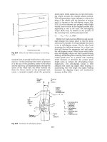
2.5 Clutch misalignment (Fig. 2.10(a±d))
Clutch faults can sometimes be traced to mis-
alignment of the crankshaft to flywheel flange
joint, flywheel housing and bell housing. Therefore,
if misalignment exists, the driven plate plane of
rotation will always be slightly skewed to that of
the restrained hub which is made to rotate about
the spigot shaft's axis. Misalignment is generally
responsible for the following faults:
1 Rapid wear on the splines of the clutch driven
plate hub, this being caused mainly by the tilted
hub applying uneven pressure over the interface
length of the splines.
2 The driven plate breaking away from the splined
hub due to the continuous cyclic flexing of the
plate relative to its hub.
3 Excessively worn pressure plate release mech-
anism, causing rough and uneven clutch
engagement.
4 Fierce chattering or dragging clutch resulting in
difficult gear changing.
If excessive clutch drag, backlash and poor
changes are evident and the faults cannot be
corrected, then the only remedy is to remove both
gearbox and clutch assembly so that the flywheel
housing alignment can be assessed (Fig. 2.10).
2.5.1 Crankshaft end float (Fig. 2.10(a))
Before carrying out engine crankshaft, flywheel or
flywheel housing misalignment tests, ensure that
the crankshaft end float is within limits. (Otherwise
inaccurate run-out readings may be observed.)
To measure the crankshaft end float, mount the
magnetic dial gauge base to the back of the flywheel
housing and position the indicator pointer against
the crankshaft flanged end face. Zero the dial gauge
and with the assistance of a suitable lever, force the
crankshaft back and forth and, at the same time,
observe the reading. Acceptable end float values
are normally between 0.08 and 0.30 mm.
2.5.2 Crankshaft flywheel flange runout
(Fig. 2.10(a))
The crankshaft flange flywheel joint face must be
perpendicular to its axis of rotation with no permis-
sible runout. To check for any misalignment, keep
the dial gauge assembly mounted as for the end
float check. Zero gauge the dial and rotate the
crankshaft by hand for one complete revolution
whilst observing any dial movement. Investigate
further if runout exists.
2.5.3 Flywheel friction face and rim face runout
(Fig. 2.10(a and b))
When the flywheel is centred by the crankshaft axis,
it is essential that the flywheel friction face and rim
rotate perpendicularly to the crankshaft axis.
Mount the dial gauge magnetic base to the
engine flywheel housing. First set the indicator
pointer against the friction face of the flywheel
near the outer edge (Fig. 2.10(a and b)) and set
gauge to zero. Turn the flywheel one revolution
and observe the amount of variation. Secondly
reset indicator pointer against the flywheel rim
and repeat the test procedure (Fig. 2.10(b)). Max-
imum permissible runout in both tests is 0.02 mm
per 20 mm of flywheel radius. Thus with a 300 mm
diameter clutch fitted, maximum run-out would be
0.15 mm. Repeat both tests 2 or 3 times and com-
pare readings to eliminate test error.
2.5.4 Flywheel housing runout (Fig. 2.10(c))
When the gearbox bell housing is centred by the
inside diameter and rear face of the engine flywheel
housing, it is essential that the inside diameter and
rear face of the housing should be concentric and
parallel respectively with the flywheel.
Mount the dial gauge magnetic base to the fly-
wheel friction face and position. Set the indicator
pointer against the face of the housing. Make sure
that the pointer is not in the path of the fixing holes
in the housing face or else incorrect readings may
result. Zero the indicator and observe the reading
whilst the crankshaft is rotated one complete revolu-
tion. Reset the indicator pointer against the intern-
ally machined recess of the clutch housing and repeat
the test procedure. Maximum permissible runout is
0.20 mm. Repeat both tests two or three times and
compare readings to eliminate errors.
44
Fig. 2.10 (a±d) Crankshaft flywheel and clutch housing alignment
45
2.5.5 Detachable bell housing runout
(Fig. 2.10(c and d))
When the gearbox bell housing is located by dowel
pins instead of the inside diameter of the engine
flywheel housing (Fig. 2.10(c)) (shouldered bell
housing), it is advisable to separate the clutch bell
housing from the gearbox and mount it to the
flywheel housing for a concentric check.
Mount the dial gauge magnetic base onto the
flywheel friction face and position the indicator
pointer against the internal recess of the bell
housing gearbox joint bore (Fig. 2.10(d)). Set the
gauge to zero and turn the crankshaft by hand one
complete revolution. At the same time, observe
the dial gauge reading.
Maximum permissible runout should not exceed
0.25 mm.
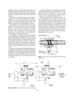
2.6 Pull type diaphragm clutch (Fig. 2.11)
With this type of diaphragm clutch, the major com-
ponents of the pressure plate assembly are a cast iron
pressure plate, a spring steel diaphragm disc and a
low carbon steel cover pressing (Fig. 2.11). To actuate
the clutch release, the diaphragm is made to pivot
between a pivot ring positioned inside the rear of the
cover and a raised circumferential ridge formed on
the back of the pressure plate. The diaphragm disc is
divided into fingers caused by radial slits originating
from the central hole. These fingers act both as leaf
springs to provide the pressure plate thrust and as
release levers to disengage the driven plate from the
drive members.
When the driven and pressure plates are bolted
to the flywheel, the diaphragm is distorted into a
dished disc which therefore applies an axial thrust
between the pressure plate and the cover pressing.
This clutch design reverses the normal method of
operation by pulling the diaphragm spring outwards
to release the driven plate instead of pushing it.
Owing to its configuration, the pull type clutch
allows a larger pressure plate and diaphragm
spring to be used for a given diameter of clutch.
Advantages of this design over a similar push type
clutch include lower pedal loads, higher torque
capacity, improved take-up and increased dura-
bility. This clutch layout allows the ratio of the
diaphragm finger release travel to pressure plate
movement to be reduced. It is therefore possible
to maintain the same pressure plate movement as
that offered by a conventional push type clutch,
and yet increase the ratio between clamp load and
pedal load from 4:1 to 5:1.
2.7 Multiplate diaphragm type clutch (Fig. 2.12)
These clutches basically consist of drive and driven
plate members. The drive plates are restrained from
rotating independently by interlocking lugs and
slots which permit axial movement, but not relative
rotational spin, whilst the driven plates are
attached and supported by internally splined hubs
to corresponding splines formed on the gearbox
spigot shaft, see Fig. 2.12.
The diaphragm spring is in the form of a dished
annular disc. The inner portion of the disc is
radially slotted, the outer ends being enlarged
with a circular hole to prevent stress concentration
when the spring is distorted during disengagement.
These radial slots divide the disc into a number of
release levers (fingers).
The diaphragm spring is located in position with
a shouldered pivot post which is riveted to the
cover pressing. These rivets also hold a pair of
fulcrum rings in position which are situated either
side of the diaphragm.
Whilst in service, the diaphragm cone angle will
change continuously as wear occurs and as the
clutch is engaged and disengaged during operation.
To enable this to happen, the diaphragm pivots
and rolls about the fulcrum rings. When the clutch
is engaged the diaphragm bears against the outer
Fig. 2.11 Diaphragm single plate pull type clutch
46
ring, but when disengagement takes place the reac-
tion load is then taken by the inner ring.
As the friction linings wear, the spring dia-
phragm will become more dished and subsequently
will initially exert a larger axial clamping load. It is
only when the linings are very worn, so that the
distance between the cover pressing and pressure
plate become excessive, that the axial thrust will
begin to decline.
2.8 Lipe rollway twin driven plate clutch (Fig. 2.13)
These clutches have two circular rows of helical coil
springs which act directly between the pressure
plate and the cover housing, see Fig. 2.13. The
release mechanism is of the pull type in which a
central release bearing assembly is made to with-
draw (pull out) three release levers to disengage the
clutch. The clutch pressure plate assembly is bolted
to the flywheel and the driven plate friction linings
are sandwiched between the flywheel, intermediate
plate and pressure plate facings. The central hub of
the driven plates is mounted on a splined gearbox
spigot shaft (input shaft). The splined end of the
input shaft is supported by a ball race bearing
mounted inside the flywheel-crankshaft attachment
flange. The other end of this shaft is supported
inside the gearbox by either ball or taper roller
bearings. There are two types of pressure plate
cover housings; one with a deep extended cover
rim which bolts onto a flat flywheel facing and the
shallow cover type in which the pressure plate
casting fits into a recessed flywheel.
The release mechanism is comprised of three
lever fingers. The outer end of each lever pivots
on a pin and needle race mounted inside each
of the adjustable eye bolt supports, which are
attached to the cover housing through an internally
and externally threaded sleeve which is secured to
the cover housing with a lock nut. Inwards from
the eye bolt, one-sixth of the release lever length, is
a second pin which pivots on a pair of needle-
bearing races situated inside the pressure plate
lugs formed on either side of each layer.
Release lever adjustment
Initially, setting up of the release levers is achieved
by slackening the locknuts and then rotating each
sleeve in turn with a two pronged fork adaptor tool
which fits into corresponding slots machined out of
the adjustment sleeve end. Rotating the sleeve one
way or the other will screw the eye bolts in or out
until the correct dimension is obtained between the
back of the release lever fingers and the outer cover
rim edge. This setting dimension is provided by the
Fig. 2.12 Multiplate diaphragm type clutch
47
Fig. 2.13 (a±b) Twin driven plate pull type clutch
48
manufacturers for each clutch model and engine
application. Finally, tighten the locknuts of each
eye bolt and re-check each lever dimension again.
Release bearing adjustment
Slacken sleeve locknut with a `C' shaped spanner.
Rotate the inner sleeve either way by means of the
slotted adjusting nut until the recommended clear-
ance is obtained between the bearing housing cover
face and clutch brake.
i.e. 9.5 mm for 355 mm Ð 1LP
13 mm for 355 mm Ð 2LP
13 mm for 294 mm Ð 2LP
Finally tighten sleeve locknut and re-check clear-
ance.
2.9 Spicer twin driven plate angle spring pull type
clutch (Fig. 2.14)
An interesting clutch engagement and release pres-
sure plate mechanism employs three pairs of coil
springs which are inclined to the axial direction of
the driven plates. These springs are mounted
between the pressure plate cover housing, which
takes the spring reaction, and the release lever cen-
tral hub (Fig. 2.14). The axial clamping thrust is
conveyed by the springs to the six to one leverage
ratio release levers (six of them) spaced evenly
around the release hub. These release levers span
between the release hub and a large annular shaped
adjustable pivot ring which is screwed inside the
pressure plate cover housing. Towards the pivot
pin end of the release levers a kink is formed so
that it can bear against the pressure plate at one
point. The pressure plate and intermediate plate are
both prevented from spinning with the driven
plates by cast-in drive lugs which fit into slots
formed into the cover housing.
In the engaged position, the six springs expand
and push the release hub and, subsequently, the
release levers towards the pressure plate so that
the driven plates are squeezed together to transmit
the drive torque.
To release the clutch driven plates, the release
bearing assembly is pulled out from the cover hous-
ing. This compels the release lever hub to compress
and distort the thrust springs to a much greater
inclined angle relative to the input shaft axis and
so permits the pressure plate to be withdrawn by
means of the retraction springs.
Because the spring thrust does not operate
directly against the pressure plate, but is relayed
through the release levers, the actual spring's stiff-
ness is reduced by a factor of the leverage ratio; in
this instance one-sixth of the value if the springs
were direct acting.
The operating characteristics of the clutch
mechanism are described as follows:
New engaged position (Fig. 2.14(a))
The spring thrust horizontal component of 2.2 kN,
multiplied by the lever ratio, provides a pressure
plate clamping load of 13.2 kN (Fig. 2.14(a)). The
axial thrust horizontal component pushing on the
pressure plate does not vary in direct proportion
with the spring load exerted between its ends, but is
a function of the angle through which the mounted
springs operate relative to the splined input shaft.
Worn engagement position (Fig. 2.14(b))
When the driven plate facings wear, the release
bearing moves forward to the pressure plate so
that the springs elongate. The spring load exerted
between the spring ends is thus reduced. Fortun-
ately, the inclined angle of spring axis to that of
the thrust bearing axis is reduced so that as the
spring load along its axis declines, the horizontal
thrust component remains essentially the same.
Therefore, the pressure plate clamping load
remains practically constant throughout the life of
the clutch (Fig. 2.14(b)).
Release position (Fig. 2.14(c))
When the clutch is released, that is when the bear-
ing is pulled rearwards, the springs compress and
increase in load, but the spring angle relative to the
thrust bearing axis increases so that a greater pro-
portion of the spring load will be acting radially
instead of axially. Consequently, the horizontal
component of axial release bearing load, caused
by the spring thrust, gradually reduces to a value
of about 1.7 kN as the bearing moves forwards,
which results in the reduced pedal effort. This is
shown in Fig. 2.14(c).
Internal manual adjustment
Release bearing adjustment is made by unscrewing
the ring lock plate bolt and removing the plate. The
clutch pedal is then held down to relieve the release
levers and adjusting ring load. The adjusting ring is
then rotated to screw it in or out so that it alters the
release lever hub axial position.
Turning the adjusting ring clockwise moves the
release bearing towards the gearbox (increasing
free pedal movement). Conversely, turning the
adjusting ring anticlockwise moves the release
bearing towards the flywheel (decreasing free
pedal movement).
49
Fig. 2.14 (a±c) Twin driven plate angle spring pull type clutch
50
The adjusting ring outer face is notched so that
it can be levered round with a screwdriver when
adjustment is necessary. The distance between each
notch represents approximately 0.5 mm. Thus three
notches moved means approximately 1.5 mm
release bearing movement.
With the pedal released, there should be approxi-
mately 13 mm clearance between the release bear-
ing face and clutch brake.
Internal self-adjustment
A clutch self-adjustment version has teeth cut on
the inside of the adjusting ring and a small worm
and spring self-adjusting device replaces the lock
plate. The worm meshes with the adjusting ring.
One end of the spring is located in a hole formed
in the release lever hub whilst the other end is in
contact with the worm. Each time the clutch is
engaged and disengaged, the release lever move-
ment will actuate the spring. Consequently, once
the driven plates have worn sufficiently, the
increased release lever movement will rotate the
worm which in turn will partially screw round the
adjusting ring to compensate and so reset the pos-
ition of the release levers.
2.10 Clutch (upshift) brake (Fig. 2.15)
The clutch brake is designed primarily for use with
unsynchronized (crash or constant mesh) gear-
boxes to permit shifting into first and reverse gear
without severe dog teeth clash. In addition, the
brake will facilitate making unshafts by slowing
down the input shaft so that the next higher gear
may be engaged without crunching of teeth.
The brake disc assembly consists of a pair of
Belleville spring washers which are driven by a
hub having internal lugs that engage machined
slots in the input shaft. These washers react against
the clutch brake cover with facing material pos-
itioned between each spring washer and outer
cover (Fig. 2.15).
When the clutch pedal is fully depressed, the disc
will be squeezed between the clutch release bearing
housing and the gearbox bearing housing, causing
the input spigot shaft to slow down or stop. The
hub and spring washer combination will slip with
respect to the cover if the applied torque load
exceeds 34 Nm, thus preventing the disc brake
being overloaded.
In general, the clutch brake comes into engage-
ment only during the last 25 mm of clutch pedal
Fig. 2.15 Clutch upshift brake (torque limiting)
51