21st Century Manufacturing Episode 1 Part 9 potx
Bạn đang xem bản rút gọn của tài liệu. Xem và tải ngay bản đầy đủ của tài liệu tại đây (577.08 KB, 20 trang )
154
Solid Freeform Fabrication (SFF) and Rapid Prototvptns Chap. 4
ComparisoD of Approxlnule
AeeurllCY
of Rapid PwlutypinK PIon:_
Sinterstation
2000 (SLS)
Sinterstation
2500 (SLS)
SOC 4600 (SGC)
0.005
0.005
0.006
13~'
SOC 5600 (SOC)
~ l5. LOM-2030H (LOM)
~~
~ FDM 2000 (FOM)
0.006
0.01
0.005
0.003
SLA-350(SLA) 0.003
SLA-500(SLA)
OJXl3
o
0.001 0.002 0.003 0.004 0.(lO5 0.006 0.007 0.008 OJXl9 0.01
Accuracy
(inches per inch)
Note that the machine suppliers quote in "thou' and that one "thou' '" 25 microns
Figure 4.15 Comparison of accuracy (as of March 2000).
4.4 CASTING METHODS FOR RAPID PROTOTVPING
4.4.1 Introduction
The classic manufacturing texts by DeGarmo and associates (1997), Kalpakjian
(1997), Schey (1999), and Groover (1999) are remarkably comprehensive in their
coverage of the casting process. The several methods of casting include:
•Lost-wax investment casting
• Ceramic-mold investment casting
• Shell molding
• Conventional sand molding
• Die casting
Rather than duplicate the material found in other books, this section focuses
on casting as it is done by rapid prototyping companies. Batch sizes from 50 to 500
are typical. The key market strategy is that casting is cheap and fast. However, it may
not be the choice for the final product because of its tolerances. Depending on the
type of casting chosen, the tolerances vary from
+/-
75microns (0.003 inch) for lost-
SLA·250(SLA)
4.4 Casting Methods for Rapid Prototyping
155
wax processes to
+/-
375 microns (0.015 inch) for standard sand castings (also see
Chapter 2).
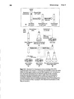
4.4.2 Lost-Wax Investment Casting
As mentioned in Chapter 1, the fundamentals of casting were invented by Korean
and Egyptian artists many centuries ago. The following steps are known as the
lost-
wax investment casting process (Figure 4.16): (a-c) a master pattern of an engi-
neering or art object is first carved from wax; (d-f) it is surrounded by a ceramic
slurry that soon sets into solid around the wax; (g) the wax is melted out through a
hole in the bottom, leaving a hollow cavity; (h) this hole is plugged, and liquid metal
is poured into the open cavity from the top; (i) after a while, the metal solidifies and
the ceramic shell can be broken away to get the part;
(j)
some cleaning, deburring,
and polishing are needed before the object is finished.
The process was greatly improved and made more accurate during World War
II for aeroengine components. Today it isused for products such asjet engine turbine
blades and golf club heads. On the top line of Figure 4.16, wax patterns are formed
from injection molds, assembled on treelike forms, and then treated with the slurry.
Alternate layers of fine refractory slip (zircon flour at 250 sieve or mesh size)
are applied, followed by a thicker stucco layer (sillimanite at 30 sieve or mesh size).
The coated components are dipped in fluidized beds that contain isopropyl silicate
and liquid acid hardener. Drying takes place in ammonia gas.The next step is to elim-
inate the wax in a steam autoclave at 150°C,fire the mold for 2 hours at 950 "C,then
pour in the liquid steel or aluminum.
In summary, the modern lost-wax method has one of the best tolerances in the
casting family because the original wax patterns are made in nicely machined molds.
Today,tolerances of
+/-
75microns (0.003inch) are readily obtainable. Also the as-cast
surface is relatively smooth and usable for the same reason. Other advantages include:
• No parting lines if the wax original is hand finished.
• Waxes with surface texture can give direct features such as the dimples on a
golf club.
•Automation of the slurry dipping is possible using robots, thereby reducing
costs.
• Products such as turbine blades can be unidirectionally solidified, giving good
mechanical properties in the growing direction.
4.4.3
Ceramic-Mold Investment Casting Procedures
The snag about the previous method is that the wax pattern is destroyed. The
ceramic-mold investment casting technique therefore employs reusable submaster
patterns in place of the expendable wax patterns. This version of investment casting
ideally involves five steps to make it efficient and to retain, as much as possible, the
fine care and expense that go into creating the original master positive in Step 1 .The
steps are as follows:
• Step L Positive: make an original master pattern with stereolithography or
machining.
156
Solid Freeform Fabrication (SFFl and Rapid Prototyping Chap. 4
(a)
Mold to make pattern
/ (bJ'"
CIW~.
Injectingwax pattern
or plastic pattern Ejecting pattern
(c) ~~
Pattern assembly
(tree)
Slurry coating Stucco coating Completed mold
(g)
(h)
(i)
Autoclaved
"~Jt.
<, /
Molten
-s-c-wax or
plastic
W~.'.CW7
,~.t
ilf
.[( J"
.:
•
::.,
.
~
Casting
Patternmeltout
Pouring Shakeout Pattern
Figure 4.1f. The lost-wax investment casting process. Upper diagrams (a) through (c) lead to
the tree of wax master patterns. Middle diagrams show the slurry and stucco being applied
Lower diagram shows the casting (adapted from literature of the Steel Founders' Society of
America).
4.4 Casting Methods for Rapid Prototyping
157
• Step 2. Negative: create a shell around the master with highly stable resin. A
negative space is created around the original positive master pattern. This shell
can be pulled apart to give a parting line.
• Step 3. Positive: create reusable submaster rubbery molds from the shells.
• Step 4. Negative: create the destroyable slurry/ceramic molds.
•Step 5. Positive: pour metal into the ceramic molds, which are then broken
apart to get the components, which must then be degated and deburred.
SLA can be used to make the original master pattern, or a CNC machine can
be used to mill the master from brass, bronze, or steel. Of course, the process can start
at Step 3, but this might damage the original master, especially if it is SLA. Also, to
get high productivity in the factory, it is preferable to have many molds at Step 3, all
of which can be made from the stable resin negative in Step 2.
Prototyping companies like to use the hard resin to fabricate the negative in
Step 2, because the resin has good dimensional stability. Note that
it
is typical to have
two resin molds, one for each side of the casting, separable by a parting line.
Once the hard resin shells have set, they can be filled with a slurry gelthat solid-
ifies to a hard "rubbery positive" for Step 3. This intermediate submaster mold can
be stripped away from the resin shells while it is still "rubbery." The material is ideal
for the rather rough handling environments of a foundry, and the rubbery properties
mean that no draft angles are needed for stripping these submasters off the resin
shells.
The Step 4 negative mold is made from a graded aluminosilicate with a liquid
binder (ethyl silicate) and isopropyl alcohol. This is poured around the subrnasters
from Step 3. Once the slurry has set, the two ceramic halves are joined to create the
inner cavity, the slurry is fired at 950 ~Cto give it strength, and the casting process,
say with molten aluminum, can begin.
After solidification, the component is broken out of the ceramic, cleaned up,
and deburred. The parting line can cause problems, but in general, good accuracy is
obtained:
+f-
125 to 375 microns
(+1-0.005
to 0.015 inch).
4.4.4
Shell Molding
An alternative form of high-accuracy casting is shell molding. Metal pattern plates
are first heated to 200°Cto 240°C.A thin wall of sand,S to 15 millimeters (0.25 to
0.75 inch) thick, is then sprayed over the plates. The sand is resin-coated to ensure
adhesion to the metal plate. Phenolic resins, with hexamethylene-tetramine addi-
tives, are combined with the silica to ensure rigid thermosetting of the sprayed sand.
The next steps are to cure, strip, and dry the sand molds, which are comparably very
accurate for casting. Once the excess sand is removed and casting is finished, accu-
racies can be as low as
+/-
75 microns (0.003 inch).
4.4.5 Conventional Sand Molding
The cruder, cheaper version of casting starting with wooden or plaster patterns is
called sand casting. A sand impression is made around the pattern with gates and
158
Solid Freeform Fabrication (SFFl and Rapid Prototyping Chap. 4
risers for the poured metal. This gives tolerances of
+1-
375 microns (0.015 inch).
Newer developments include:
1. A high-pressure jolt-and-squeeze method: Here mechanical plungers push the
sand against the mold at a jolt of 400 psi. This gives a tighter fit of the sand
against the pattern and hence better tolerances after casting.
2. Carbon dioxide block molding: Here the interfacing between the sand and tbe
pattern is made up of a special material about 12 millimeters (0.5 inch) thick.
It is a refractory mix of zircon or very fine silica, bonded with 6% sodium sili-
cate, which is then hardened by the passage of carbon dioxide.
4.4.6
Die Casting
Die casting is predominantly done by the high-pressure injection of bot zinc into a
permanent steel die. Today, the die or mold for this type of casting is almost certain
to be milled on a three- or five-axis machine tool.
Die costs are relatively high, but smooth components are produced with accu-
racies in the range of +1- 75 microns (0.003 inch). However, these high costs for the
permanent molds mean that die casting does not really fit into the rapid prototyping
family. It is mostly used for large-batch runs of small parts for automobiles or con-
sumer products. Since low melting point materials such as zinc alloys are used in the
process, component strengths are relatively modest.
Today, the injection molding of plastics (Chapter 8) is often preferred over zinc
die casting.
4.5 MACHINING METHODS FOR RAPID PROTOTYPING
4.5.1
Overview
Chapter 7 deals with the generalized machining operation including the mechanics
of the process. This chapter focuses on advances in CAD/CAM software that allow
CNC machining to be more of a "turnkey rapid prototyping" process. One goal isto
fully automate the links between CAD and fabrication. Another goal is to minimize
the intensely hands-on craft operations (e.g., process planning and fixturing) that
demand the services of a skilled machinist.
CyberCut™ is an Internet-based experimental fabrication test bed for CNC
machining. The service allows client designers on the Internet to create mechanical
components and submit appropriate files to a remote server for process planning and
fabrication on an open-architecture
CNe
machine tool. Rapid tool-path planning,
novel fixturing devices, and sensor-based precision machining techniques allow the
original designer to quickly obtain a high-strength, good-tolerance component
(Smith and Wright, 1996).
4.5.2 WebCAD: Design for Machining "on the Internet" on
the Client Side
A key idea is to use a "process aware" CAD tool during the design of the part. This
prototype system is called
WebCAD
(Kim et al., 1999). Sun Microsystems' Java™_
a portable, object-oriented, robust programming language similar to C+ +-is being
4.5 Machining Methods for Rapid Prototyping
159
used as a framework for serving mini-applications.The GUI isa 2.5D feature-based-
design system that uses the destructive solidgeometry (DSG) idea introduced in the
last chapter (Cutkosky and Tenenbaum, 1990;Sarma and Wright, 1996).Recall that
the user starts out with a prismatic stock and removes primitives or "chunks" of
material. By contrast, conventional constructive solid geometry (CSG) means
building up a part incrementally from "nothingness." In the "destructive" paradigm,
instead of allowing arbitrary removal, the user is also constrained to removing cer-
tain shapes of material, referred to as features. These features take the form of
pockets, blind holes, and through-holes.
WebCAD also contains an expert system capturing rules for machinability.At
the top of Figure 4.17, the designer is shown being guided by these rules. For
example, a "forbidden zone" is imposed around a through-hole feature to prevent it
from being designed too close to an edge. In the event that the designer violates a
rule, a "pop-up" window advises on an appropriate remedy by moving the hole fur-
ther into the block-typically by its radius dimension. WebCAD also uses a
WYSIWYG ("what you see iswhat you get") environment, with explicit cutting tool
selection and visible comer radii on pockets. At the time of this writing, further
improvements also include Ireeform surface editing and selection ofdifferent cutting
tool sets depending on final fabrication location (Kim, 2000).
The rationale for imposing destructive features upon the designer is that each
of these features can readily be mapped to a standard CNC milling process. The
scheme thus resembles the interaction between a word processor and a printer
regarding the "printability" of the document. It is easyto criticize that the restriction
to DSG limits the set of parts that can be designed. However, the key advantage of
this design environment is that the design-to-manufacture process is more deter-
ministic than conventional methods, which rely on unconstrained design and on
looser links between design, planning, and fabrication. Experience shows that
designers are somewhat concerned at first that they are constrained; however, the
opportunity to be provided with the correct part veryquicklyproves to be attractive.
4.5.3 Planning on the Server Side
When the client's design is finished, the resulting geometry can be sent over the
Internet to a process planner residing on a remote server. An automated software
pipeline takes the geometry and determines in which order the features should be
cut, the exact tool paths to traverse, cutting feeds,and spindle speeds for a machine
tool.
Macroplanning
orders the individual features and creates the specific
machining setups in fixtures.CyberCut's current macroplanner is a feature recogni-
tion module that can reliably extract the volumetric features from
2.5V
parts. The
output of the module isnotjust a machining feature set but a rich data structure that
also givesimportant connectivity information that relates one feature to another. A
recent advance in the macroplanner is its ability to recognize and process features
containing freefonn surfaces (Sundararajan and Wright, 2000).
2A 2.50
feature
is
a machinable feature with arbitrary outside peripheral contour and a uniform
sweeping depth into the block being machined
160
Solid Freeform Fabrication (SFF)and Rapid Prototyping Chap. 4
Desip.
(WebCAD)
A novel JAVA-based design
with WYSIWYG
part features
A design consultant: 'The hole
is too dose to the edge"
Freeforrn feature based
manufacture
Custom control algorithms
for precision and flexibility
Sensor integration
FIgure 4.17 The CyberCul project: integrated design, planning, and f"bricotion.
MicropJanning and tool-path planning decompose the DSG volumes into spe-
cific tool motions. Colloquially speaking, this is the step that is like lawn mowing:
each volume has to be carved out with a specific tool diameter, and the overlap
between each strip has to be considered in relation to part tolerance and surface
roughness. The comers of pockets
Gust
like lawns) might require special methods.
Mill;l'opiaD
• Make hole 1 before
pocket 2
Change setup
• Refixture
Mkro_
• Use tool 1
Cutatl600rprn
• Feedrate Jrnm/s
• Perform one pass
F_brlcatloll
4.6 Management of Technology 161
Freeform surfaces must be divided into flat and steep regions.The flat regions are
machined with a projecting spiral tool-path pattern, and the steep regions are
machined with a slicingtool-path pattern.This yieldsgood tool-path uniformity and
only moderate computational complexity.The decomposition aims at minimizing
machining time within the constraints of the specified surface roughness, tolerance,
and machine tool safety.The time of individual operations can also be estimated,
which can be sent back to the designer, providing an early estimation of the
machining costs.
4.5.4
Fabrication by Milling on the Server Side
Finally,a stream of NC commands performs the machining on an open-architecture
millingmachine.(Bycontrast, ifit had been determined alongthe waythat the client
would have been better served by SFF technology,CyberCut can connect to a fused
deposition modeling [FDM] machine.) The particular milling machine being used is
an open-architecture machine that can execute advanced tool-path trajectories. One
example isamachine path interpolator that can traverse complicated freeform paths
represented by NURBS. This ability brings a richer surface generation capability to
the ostensibly traditional machining process.By doing so, it continues to compete
with the SFFmethods from the point ofviewof geometric complexity (Hillaire et al.,
1998). More details of the open-architecture machine tool itself are reserved for
Chapter 7 on machining.
4.6 MANAGEMENT OF TECHNOLOGY
4.6.1
Summary
Solid freeform fabrication (SFF) techniques and conventional rapid prototyping
techniques such as machining and casting are key technologies for improving
product realization cyclesand reducing time-to-market. The availabilityof lntemet-
based software tools (Berners-Lee, 1989; Java, 1995) has accelerated the links
between CAD and prototype creation. The Internet has also allowed accessto man-
ufacturing sitesin many different countries (Smith and Wright, 1996;DeMeter et al.,
1995;Mitsuishi et al., 1992;Frost and Cutkosky,1996;Finin et al.,1994).In summary:
•SLA emerges as the most commercially accepted of the newer SFF proto-
typing methods.
•SLS emerges as a very useful, commercially accepted alternative to SLA for
overhanging structures needing support and for stronger materials that can be
sintered rather than photocured.
•FDM is an excellent choice for an in-house machine that can be used by an
industrial design team for an iterative series of prototypes.
•LOM isexcellent for larger components.
•3-D printing and planarization using the inexpensive Sanders and Z-
Corporation machines are gaining commercial acceptance at the time of this
writing. Very inexpensive 3-D digitizers coupled with miniature milling
'62
Solid Freeform Fabrication (SFF) and Rapid Prototyping Chap.4
machines are also entering the market (see URL for Roland Digital Group at
the end of the chapter} .
• Machining and casting remain central to the rapid prototyping field, especially
for high-strength prototypes and longer batch runs of several prototypes.
4.6.2
Future Trends
The accuracy of processes such as stereolithography and selective laser sintering is
improving as time goes by. These processes are being used more and more in the cre-
ation of the original, first master for casting and for plastic injection molding. As con-
sumer products such asstereos, cellular phones, personal digital assistants (PDAs), and
handheld computers (Richards and Brodersen, 1995) begin to look more aerody-
namic, there is a need to create molds that have unusual curves and reentrant shapes;
these are easy to create in SLA or S~ especially in comparison with machining.
It has nonetheless been emphasized that SFF's accuracy is poor in comparison
with machining. Overhanging structures may be hard to support during fabrication,
and there are problems with component warping during curing. While simple shapes
might have accuracies of
.ct-:
25 to 75 microns (0.001 to 0.003 inch), the range for
complex shapes might be as high as
+1-
125 to 375 microns (0.005to 0.015 inch).
While the strength of SFF parts is today less than machined parts, new trends
are closing the gap.The FDM parts made by the Stratasys machine can be formed in
near full strengthABS and similar polymers. Cheung and Ogale (1998),for example,
have increased the strength of photopolymers by fiber reinforcement. Also, research
at Sandia Laboratories on a process called laser engineered net shaping (LENS) is
permitting direct fabrication of high-strength metal molds. This and similar projects
are modified versions of DTM Inc.'s SLS process.
At the same time, CA O/CA M techniques for machining are advancing rapidly.
For example, the CyberCut freeform design tools linked to open-architecture milling
machines will continue to expand machining's capability (Greenfeld et al., 1989;
Schofield et al., 1998; Hillaire et al., 1998).There is a subtle point to be made here:
much of the increased activity in the SFF prototyping methods was originally
prompted by the poor communication between CAD and CNC machine tools.
During the late 1980s, stereolithography's competitive edge over machining came
from the fact that the CAD model could be instantly "sliced" and then turned into
laser scanning paths for rapid part production. With the CyberCut methodology and
open-architecture control, the conventional machining process can be equally com-
petitive from an art-to-part speed standpoint, and it continues to give the high-
accuracy and product integrity qualities that it always gave.
The evidence is thus clear that the capabilities in both the machining and the
SFF fields are constantly improving. It has also been noted that several of the
methods such as 3-D printing with planarization, SGc, and SDM combine deposi-
tion with machining "to get the best of both worlds." Perhaps in a similar way,the 3D
Systems' QuickCast method uses "the best of SLA combined with the best of invest-
ment casting." In QuickCast, disposable SLA patterns are fabricated with distinctly
hollow internal structures. When the ceramic shells for casting are created around
these hollow SLA patterns, the latter collapse inward, leaving the casting mold intact
4.7 Glossary
163
and ready for use.This process, described by Jacobs (1996, 183-252), is gaining rapid
acceptance commercially.
The issues mentioned are predominantly technical. As this chapter draws to a
close,it is important to recall an earlier point from Chapter 2 that "prototypes structure
the design process" (see Kamath and Liker, 1994).Physical prototypes focus the efforts
of a distributed design team, especially if subcontracting is a big part of the process.
Perhaps the most important conclusion is this: each manufacturing process will
playa vital role at different points in the product development cycle. SFF techniques
will be more evident at the front end, machining will be more evident partway
through to create highly accurate molds, and plastic injection molding will be most
evident in the final high-volume production method for the consumer's product.
Once again it must be emphasized that "manufacturing in the large" is an integration
of many software tools, physical processes, and market strategies.
In summary, rapid prototyping dramatically accelerates time-to-market.
• Psychologically, it focuses the attention of the members of the design team in
a "learning organization" (see Chapter 2).
• Physically, it reduces the time necessary to make a full production die from
hardened steel and to launch into mass production.
4.7 GLOSSARY
4.7.1
01.
Casting
Low-pressure casting, often of liquid zinc, into a machined mold.
4.7.2
Electrodischarge Machining IEDM.
The use of an electrode to melt and vaporize the surface of a hard metal. Usually
restricted to low rates of metal removal of very hard metals.
4.7.3 G-Codes
The standard low-end machine tool command set that gives motion, for example,
G1
=
linear feed.
4.7.4 Injection Molding
Viscous polymer is extruded into a hollow mold (or die) to create a product.
4.7.5 Ink-Jet Printing in 3-0
Rapid prototyping by rolling down a layer of powder and hardening it in selected
regions with a binder phase that is printed onto the powder layer.
4.7.6 Investment Casting
The word investment is used when time and money are invested in a ceramic shell
that is subsequently broken apart and destroyed. The original positive master that is
'84
Solid Freeform Fabrication (SFF) and Rapid Prototyping Chap. 4
used to create the negative investment shell can be made
by
several processes. Lost-
wax and ceramic mold are the two most common.
4.7.7 Laminated Object Modeling (LOM)
Rapid prototyping by laser cutting the top layer of a stack of paper, each layer of
which is glued down.
4.7.8 Lapping and Polishing
Final finishing and smoothing of a surface that has already been machined. The
surface-lapping operation is usually done on flat lapping plates loaded with diamond
paste down to 0.25 microns in diameter.
4.7.9 Machining
General manufacturing by cutting on a lathe or mill; chip formation from a solid
block rather than forging, forming, or joining.
4.7.10 M·Codes
The standard low-end command set for machine tool operations that are not related
to x,
y,
or z motion of the axes-for example, M6
==
call tool into spindle.
4.7.11 Near-Net Shape
Forming, forging, or sintering operations that produce an object "nearly" to its final
shape so that only minor finish machining is needed.
4.7.12 Plastic Injection Molding
As "injection molding," described earlier. Note: Zinc die casting also involves "injec-
tion" into dies or molds.
4.7.13 Prototyping (Prototype)
"The original thing in relation to any copy, imitation, representation, later specimen
or improved form" (taken from Webster's dictionary).
4.7.14 Rapid Prototyping (RP)
A new genre of prototyping, usually associated with the SFF family of fabrication
methods. Emphasis is on speed-to-first-model rather than fidelity to the CAD
description.
4.7.15 Selective Laser Sintering ISLSI
Rapid prototyping by laser sintering of polymer or ceramic powders. The laser moves
as a point source across the surface of the powder, first sintering the bottom slice of
the desired object. A roller spreads more powder and a second layer is sintered, also
fusing to the one below.
4.8 References
'66
4.7.16 Shape Deposition Manufacturing ISDM)
Rapid prototyping with alternative deposition runs followed by machining runs
across an object to build up complex prototypes.
4.7.17 Solid Freeform Fabrication ISFFI
A family of processes in which a CAD file of an object is tessellated, sliced, and sent
to a machine that can quickly build up a prototype layer by layer.
4.7.18 Solid Ground Curing ISGCI
Rapid prototyping, also by laser curing of photocurable polymers, but done layer by
layer through a photomask rather than by laser point sources.
4.7.19 Stereolithography ISLA)
Rapid prototyping by laser curing a photocurable liquid. The laser moves as a point
source across the surface of the liquid, first curing the bottom slice of the object. This
slice moves down on an elevator by 5U to 375 microns (0.002 to 0.015 inch), depending
on desired accuracy. The next layer is then photocured, also fusing to the one below.
4.7.20 Tessellation
Representing the outside surfaces of an object by many small triangles, like a mesh
thrown over and drawn around the object. This leads to an ".STL" file of the vertices
and the surface normals of the triangles.
4.7.21 3-D Printing/Plotting
Rapid prototyping by printing/plotting thin jets of polymer onto a fixtureless base-
plate followed by simple machiniug/planenzation.
4.8 REFERENCES
ACIS Geometric Modeler. 1993. Technical Overview. Spatial Technology, lnc., Version 1.5.
Ashley,S. 1991. "Rapid prototyping systems." Mechanical Engineering 34-43.
Ashley,S. 1998. "RP industry's growing pains." Mechanical Engineering 64-67.
Au, S., and P. K. Wright. 1993.A comparative study of rapid prototyping technology. In Intel-
ligent concurrent design: Fundamentals, methodology, modeling, and practice. ASME Winter
Annual Meeting, New Orleans. Louisiana. 73-82.
Bearnan.J, 1.,1.W. Barlow, D. L. Bourell, R. H. Crawford, H. L. Marcus. and K. P. McAlea.l997
Solid freeform fabrication. A new direction in manufacturing: With research and applications in
thermal laser processing. Norwell, MA: KJuwer Academic Publishers.
Berners-Lee, T.1989. Information management:A proposal. CERN Internal Proposal.
Bouldin, D., ed. 1994. Report of the 1993 workshop on rapid prototyping of microelectronic
systems for universities. National Science Foundation Workshop.
Cheung, T. S., and A. A Ogale. 1998. Processing of multilayer fiber reinforced composites by
3D photolithography. In Proceedings of the 1998 NSF Grantees Design and Manufacturing
Conference, Monterrey, Mexico, 557-559. Arlington, VA: National Science Foundation.
168
Solid Freeform Fabrication (SFF) and Rapid Prototyping Chap. 4
Cohen, E., S. Drake, L. Gursoz, and R. Riesenfeld. 1995. Modeling issues in solid freefonn
fabrication. NSF Solid Freeform Fabrication Workshop II, Design Methodologies for Solid
Freeform Fabrication, June 5 6, Pittsburgh, PA.
eutkosky, M. R., and 1. M.Tenenbaum. 1990. A methodology and computational framework
for concurrent product and process design. Mechanism and Machine Theory 25
(3):365-381.
DeGarmo, E. P., 1.T. Black, and R.A. Kohser. 1997.
Materials and processes in manufacturing,
8th ed. New York: Prentice-Hall.
DeMeter, E.
c.,
Q.
Sayeed, R. E. DeVor, and S. G. Kapoor. 1995. An Internet model for tech-
nology integration and access part 2: Application to process modeling and fixture design.
MTAMRI Report 1995. University of Illinois.
Dutta, D. 1995. Layered manufacturing in Project Maxwell. NSF Solid Freeform Fabrication
Workshop II, Design Methodologies for Solid Freefonn Fabrication, June 5-6, Pittsburgh,
PA.
Finirt, T., D. McKay,
R
Fritzson, and
R
McEntire. 1994. KQML:An infonnation and knowl-
edge exchange protocol. In Knowledge building and knowledge sharing, edited by Kazuhiro
Puchi and Toshio Yokoi. Tokyo, Japan: Ohmsha and lOS Press.
Frost,
R,
and M. Cutkosky. 19%. An agent-based approach to making rapid prototyping
processes manifest to designers. ASME Symposium on Virtual Design and Manufacturing.
Greenfeld, I., F. B. Hansen,and P. K. Wright. 1989. Self-sustaining, open-system machine tools.
In
Proceedings of the i7th North American Manufacturing Research institution 17:281-292.
Groover, M. P. 1999. Fundamentals of modern manufacturing. Upper Saddle River, NJ:
Prentice-Hall.
Heller, T. B. 1991. Rapid modeling-What is the goal? In The Second international Con-
ference on Rapid Proto typing, 242-244. Dayton, OH: Rapid Prototype Development Labora-
tory (RPDL), 242-244.
Hillaire, R, L. Marchetti, and P. K. Wright. 1998. Geometry for precision manufacturing on
an open architecture machine tool (MOSAIC-PC). In Proceedings Of the ASME Interna-
tional Mechanical Engineering Congress and Exposition, 8: 605-610. Anaheim, CA: MED.
Jacobs, P. F. 1992. Rapid prototyping and manufacturing: Fundamentals of stereolithography.
Dearborn, MI: Society of Manufacturing Engineers.
Jacobs, P.F. 1996. Stereolithography and other rapid prototyping and manufacturing technolo-
gies. Dearborn, MI: Society of Manufacturing Engineers.
Java, 1995, is a trademark of SUDMicrosystems, Incorporated. Documentation can be found
at . (Also refer to 1. Gosling and H. McGilton. "The Java Language
Environment: A White Paper,"Technical Report, Sun Microsystems, 1995.)
Kai, C. C. 1994. Three-dimensional rapid prototyping technologies and key development
areas. Computing
&
Control Engineering JournalS (4):20lJ 206.
Kalpakjian, S. 1997. Manufacturing processes for engineering materials, 3d ed. Menlo Park,
CA: Addison Wesley Longman.
Kamath, R.
R,
and 1. K. Liker. 1994. A second look at Japanese product development. Har-
vard Business Review. (Reprint Number 94605).
Kim,1. H., F. C. Wang, C. Sequin, and P. K. Wright. 1999. Design for machining over Internet.
Paper presented at the Design Engineering Technical Conference (DETC) on Computer
Integrated Engineering, Las Vegas, NV. Paper Number DETC'99/CIE-9082.
Kim, 1. H. 2000. WebCAD 2000: Distributed CAD tool for machining. Master of Science
Thesis, Department of Computer Science, University of CalUornia, Berkeley.
4.8 References
167
Kochan, D. 1993. Solid freeform manufacturing: Advanced rapid prototyping. New York and
Amsterdam: Elsevier.
Kruth, 1. P. 1991. Manufacturing by rapid prototyping techniques. Annals of the CIRP 40
(2):603 614.
Kumar, V., P.Kulkarni, and D. Dutta. 199f\. Adaptive slicing of heterogeneous solid models for
layered manufacturing. University of Michigan Technical Report, UM-MEAM-98-02.
Manufacturing Studies Board (National Research Council). 1990. Rapid prototyping facilities
in the U.S. manufacturing research community. Edited by T. C. Mahoney.
McMains, S. 1996. Rapid prototyping of solid three dimensional parts. Master of Science
Thesis, Computer Science, University of California, Berkeley.
McMains, S., C.S. Sequin. and 1 Smith. 1998. SIF: A solid interchange format for rapid proto-
typing. Paper presented at the 31st CIRP International Seminar on Manufacturing Systems.
University of California. Berkeley.
Mead, C, and r Conway.
19RO.
Thc F'altech intermediate form for
J
.SI layout description. In
Introduction ro VLSI Systems, 115-127. Addison Wesley.
Mitsuishi, M., S.wansawa, Y. Hatamura, T. Nagao, and B. Kramer. 1992. A user friendly man.
ufacturing system for hyper-environments, In Proceedings of the 1992 IEEE International
Conference on Robotics and Awomation. 25-31.
MOSIS, 2000. University of Southern California's Information Sciences Institute-The
MUSIS VLSI Fabrication Service. hnosisl.
NSF. 1994. Solid Preeform Fabrication Workshop
J.
New Paradigms for Manufacturing,
Arlington VA.
NSF. 1995. Solid Freeform Fabrication Workshop II. Design Methodologies for Solid Freeform
Fabrication, June 5 6, Pittsburgh, PA.
Richards, B., and R. Brodersen. 1995. InfoPad: The design of a portable multimedia terminal.
In Proceedings of the Mobile Multimedia Conference, 2. Bristol, England.
Sachs, E., M. Cima, J. Bredt, A. Curodeau, T. Fan, and D. Brancazio. 1992. CAD-casting: Direct
fabrication of ceramic shells and cores by three dimensional printing. Manufacturing Review
5 (2):117-126.
Sachs, E., N. Patrikalakis, D. Boning, M. Cima, T.Jackson, and R. Resnick. 2000. The distributed
design and fabrication of metal parts and tooling by three dimensional printing. In Proceed-
ings of the 2000 NSF Grantees Design and Manufacturing Conference. Arlington, VA: Univer-
sity of British Columbia and National Science Foundation.
Sarma,S., and P. K. Wright. 1996.Algorithms for the minimization of setups and tool changes
in "simply fixturable" components in milling.JourfUll of Manufacturing Systems 15, (2):95-112.
(Also see S. Sarma, S. Gandhi, and P. K. Wright. 1995. Reference free part encapsulation: A
universal fixturing technology for rapid prototyping by machining. In Concurrent Product and
Process Engineering. 1:339-351.Anaheim, CA; MED.).
Schey,
J.
A. 1999. Introduction to manufacturing processes. New York: McGraw-Hill.
Schofield, S., F. C. Wang, and P. K. Wright. 1998. Open architecture controllers for machine
tools part 1: Design principles, part 2:A real-time, Quintic spline interpolator.Jownef of Man·
ufacturing Science and Engineering 120:417 432.
Smailagic,A., and D. P. Siewiorek. 1993.A case-study in embedded system design:The VuMan
2 Wearable Computer. IEEE Design and Test of Computers,
56-fJ7.
Smith,
C,
and P. K. Wright. 1996. CyberCut: A World Wide Web based design to fabrication
tool. Journal of Manufacturing Systems 15 (6):432-442.
'68
Solid Freeform Fabrication (SFF) and Rapid Prototyping Chap. 4
Smith, D. 2000. 3DP prototyping at Motorola. Personal communication.
Sundararajan, V., and P. K. Wright. 2000. Identification of multiple feature representation by
volume decomposition for 2.5 0 components. Transactions af the ASME. Jou17UIl of Manu-
facturing Science and Engineering 122 (1): 280-290.
University of California, Los Angeles (UCLA). 1994, University Extension, Department of
Engineering, Information Systems, and Technical Management, Short Course Program,Rapid
Prototyping:Technologies and Applications.
Weiss, L. E., E. L. Gursoz, F. B. Prinz, P, S. Fussell, S. Mahalingam, and E. P. Patrick. 1990. A
rapid tool manufacturing system based on stereolithography and thermal spraying. Manufac-
turing Review 3 (1):40-48.
Weiss, L. E., and F. B. Prinz. 1995. Shape deposition processing. NSF Workshop II. Design
Methodologies for Solid Freefonn Fabrication, June 5-6, Pittsburgh, PA.
Weiss, L. E., R. Merz, F. B. Prinz, G. Neplotnik, P. Padmanabhan, L. Schultz, and K.
Ramaswarni, 1997. Shape deposition manufacturing of heterogeneous structures. SME
Journal of Manufacturing Systems 16:239-248.
Weiss, L. E., and F.B.Prinz. 1998. Novel applications and implementations of shape deposition
manufacturing. Paper presented at the Naval Research Conference.
Woo, T. 1992. Rapid prototyping in CAD. Computer Aided Design 24:403 404.
Woo, T. 1993. Rapid automated prototyping:An introduction. Industrial Press.
Wright, P. K., D.A. Boume,J.A. E. Isasi, 0. C. Schatz, and
J
0. Colyer. 1982. A flexible manu-
facturing cell for swaging. Mechanical Engineering 104 (10):76-83.
4.9 BIBLIOGRAPHY
Benett, 0., ed. 1996. Developments in rapid prototyping and tooling. Mechanical Design Pub-
lication Ltd. London: Bury-Saint Edmunds.
Koenig, D. T. 1987. Manufacturing engineering: Principles for optimization. Washington, New
York, and London: Hemisphere Publishing Corporation.
4.10 URLS OF INTEREST
4.10.1 Rapid Prototyping
1. ~bremen.de
2.
3. orola-com
4.
5. bttp:llwww.cs.hut.fiI-adolrp/rp.btml
6. bttp:l/www.cubital.comlcubitall
7. bttp:llwww.helisys.com
8.
9. l
10.
11. (see products Modela and Picza)
U.
l
4.11 Interactive Further Work
,
4.11 INTERACTIVE FURTHER WORK
4.11.1 Internet-Based CAD/CAM
The CyberCut WebCAD design environment can be found at the following
URL
. Jaeho Kim and Ashish Mohole have been
the creators of WebCAD, <>, and we wel-
come
yOUT
comments and suggestions.
4.11.2 The Assignment
Enter this design environment to design a part. Also answer the basic question that
followsbut read the next section first.
4.11.3 Getting Started
It is possible to get this to run at home on a PC comparable with:
•Dell Optiplex Gxi with
28,800
bps modem connection
•Microsoft's Internet Explorer 5.0
There have been difficulties in getting WebCAD to run on Solaris versions of
Netscape.
First-time users should click on the "Gallery" on the main menu to get some
idea of the kind of parts that can be made or type in the location
. Next, click on "WebCAD" in the
"Design" section ofthe front page.From here it ispossible to clickon the "WebCAD
2000 Quick Start Manual" to view a tutorial or click on "Run WebCAD 2000" to
begin using the CAD tool.
The "WebCAD 2000Quick Start Manual" canbe printed out for easyreference.
•At a university the download will take a minute or so.
• But for a design from home it takes a long time to get the byte code.It could
take at least 5 minutes to download all the code.
•After clicking on "Run WebCAD 2000" go and make a cup of tea and watch
ESPN or MTV for
5
minutes.
•A "Welcome to WebCAD
2000"
window and a "Tool bar" window should
appear.
•Click on "Make new part" and proceed with selecting stock as indicated. The
program forces the selection of stock before any design can begin.
4.11.4 Questions to Add to the Assignment
At a minimum, try to design a simple paperweight out of aluminum that is a block
with some initials on one side of it.Print out the design and attach it to the questions
(recall from the MAS assignment about how to print from a browserl).
1. Where was the work done?
2. What kind of machine?
170
Solid Freeform Fabrication (SFF) and Rapid Prototyping Chap.4
3. Which Internet browser?
4. How long did the full download take?
5. Did the "WebCAD 2000 Quick Start Manual" get the design on track quickly?
6. Did the gallery page help?
7. How long did
it
take to feel comfortable with the graphic user interface
aUI?
8. How long did the design take?
9. What part type (or name) was designed?
10. Provide suggestions for the software development in the future.
CHAPTER
SEMICONDUCTOR
MANUFACTURING
5.1 INTRODUCTION
As already described, the material in this book is organized as "a journey along
the product development path with emphasis on the fabrication techniques."
Chapters 2 through 4 focused on the needs of the customer, conceptual design,
detailed design, and rapid prototyping. The emphasis was on mechanical com-
puter aided design/manufacturing (CAD/CAM) rather than electronics. However
today, nearly every consumer product has an integrated circuit (fC) in
it.
And the
more "high-tech" a product is, obviously the more sophisticated the inner elec-
tronics become. So
it
makes logical sense to study the inner workings of
today's
consumer products as discussed in the next chapters in the book. Colloquially
speaking, integrated circuits and their associated electronics are the "brains" that
will fit into the outer casings or "bodies" that were just prototyped in Chapter 4,
by a method such as fused deposition modeling (FDM), or mass-produced in
Chapter 8, by injection molding.
5.2 SEMICONDUCTORS
For the automobile and aerospace industries of today, it is not too much of an exag-
geration to state that "an automobile is a computer on wheels" or that "an airplane
is a flying computer." Even very traditional manufacturing industries such as steel-
making can survive only by using computer control and sensors to obtain exacting
quality assurance, In today's "information age revolution" all manufacturing indus-
tries have the integrated circuit and the microprocessor at their core. In the same
way, in the industrial revolution 200 years ago, all manufacturing industries had the
steam engine at their core.
171
17Z
Semiconductor Manufacturing Chap. 5
The next two chapters examine the technology and management issues in two
critical areas of manufacturing. Chapter 5 focuses on the fabrication of semicon-
ductors. These are the basic building blocks of integrated circuits (also called l'Cs
or microchips or just chips). Semiconductor manufacturing has a worldwide com-
pounded annual growth rate of 18%. Today, semiconductors are a $150 billion a
year industry (see Appendix 1 of this chapter, Section 5.18). This rises to as much
as $200 billion
if
the semiconductor equipment manufacturers are included. The
projections take semiconductors to a $1trillion industry over the next decade (see
the Semiconductor Industry Association, 1997). Semiconductors and ICs are the
"brains" of every computing device manufactured today, from supercomputers to
personal computers to kitchen appliances. Chapter 6 will examine computer man-
ufacturing including the assembly of ICs, printed circuit boards, and other key
components into a device. It is worth glancing ahead to Chapter 6 to see how every-
thing fits together.
5.3 MARKET ADOPTION
Tremendous leaps in computer science and electrical engineering technology over
the past few decades have made possible the wide range of computing devices that
are available today. These go vastly beyond the original transistor invented in 1947,
the first IC in 1958, and the first microprocessor introduced commercially in 1971.
For example, comparisons between the original microprocessor, the Intel 4004, and
one of today's processors show the dramatic progress (Figure 5.1a has 2,300 transis-
tors on a3 x 4 mm chip; Figure 5.1b has 1.3 million on an 11 X 15 mm chip).
Increasingly, though, the main force driving the computer industry is not new
basic knowledge but the market. Computer users are more sophisticated and
demanding than ever. They want higher performance, more functionality, smaller
dimensions, and interconnectivity with other products-all at supercompetitive prices.
These two chapters on semiconductor and computer manufacturing are there-
fore placed in this sequence in the book for another reason besides the journey along
the product development life cycle.Already, many aspects of semiconductor and per-
sonal computer manufacturing have placed these technologies well along the market
adoption Scshaped curves in Chapter 2. Gone are the days when the semiconductor
industry or a computer manufacturer could rely solely on innovative designs and dis-
regard the integration with manufacturing and efficient production processes. Those
were the days, say around 1980,when consumers marveled at the user-friendly icons
of Apple's machines in comparison with the nonintuitive DOS commands. Such
friendly graphical interfaces created a brand loyalty for Apple that won and kept cus-
tomers well into the late
19808.
But today, semiconductors and computers are headed
toward the market maturity of autos and steel, which are dealt with in later chapters.
To compete today, semiconductor manufacturers, computer makers, and their sup-
pliers must therefore make better products at lower cost. Semiconductor fabs must
now focus on high-yield manufacturing systems. Computer makers need to design
customer-focused products, "outsource'' to agile assembly factories, and orchestrate
rapid supply chains. At the time of this writing around the year 2000, it is clear that
5.3 Market Adoption
173
Fipre5.1
(a)ThefirstmicTOprocessor,
Intel's 4004, includes 2,300 transistors on
a3 x 4mm chip (courtesy Intel). (b) The
MIPS 1echnology Inc. R4000 processor
includes 13 million trlUlSistors on an 11
X 15 mm cbip. The right_hand side
contains the data path for the integer
portion of the microprocessor. The left-
hand side contains the data path for the
floating point processor. The central area
is the controller. The two large blocks on
the top contain tbe fast, short-term cache
memory (courtesy MIPS Thclmology Inc.
Reprinted from D.A Patterson and 1. L
Hennessy'.
Comp.uur OrganktUion und
1JeBisn.'n.e
HfIIllwaNISo/ttwu'e
l111erftlu,
Morpn Kaufmann PubIiIhe:n, 1994, 24).