21st Century Manufacturing Episode 1 Part 6 pptx
Bạn đang xem bản rút gọn của tài liệu. Xem và tải ngay bản đầy đủ của tài liệu tại đây (612.07 KB, 20 trang )
94
Product Design, Computer Aided Design (CAD), and Solid Modeling Chap. 3
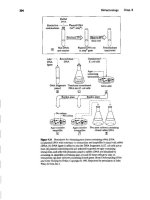
Figure 3.9 Outline ofthe base exterior before the trimming process.
F1gure3.10 Outline of the base exterior
after the trimming process.
A good place to start isthe shallow rounded pocket in the bottom face, because
many consumer electronics products, including telephones, have a cover plate on the
bottom. This is more like a shallow recess that the cover plate will eventually nestle
into. The cover plate will close over the larger internal cavity that houses the printed
circuit boards and wires The plate generally follows the contour of the bottom sur-
face of the object. For the joystick, the base plate itself is a flat trapezoid with
rounded corners.
A shallow rounded pocket will thus be drawn in the next few images to accom-
modate the plate. This task begins in Figure 3.11. First, the straight lines of a trape-
zoid are drawn that remain equidistant from the outside edges of the bottom. These
will then be connected, next rounded, and then copied and repeated for the depth of
the cavity.
In the first construction step, the line
i
is drawn parallel to the base, at a small
distance
w
in the y direction from a, This line travels some distance past the outline
Ilemporaryoonstructionlines(ceanddf)
3.8 First Tutorial: Wire Frame Construction
95
Figure 3.11 Initial formation of the cavity in the base exterior
of the object on each side. Line
ii
begins by placing a tiny line of length w perpendi-
cular to the other edge. The full extent of line fi is then constructed from the end point
of this short construction line
w.
It goes past the front of the object, parallel to the
angled bottom edge. The line is completed by extending it with the extend command
such that it intersects line
i,
The extend command finds the intersection automati-
cally. Line
iii
is constructed in a similar manner from the short construction line w2
from the front face. Once one of the lines marked
"il"
is constructed on the right side
of the object. it is mirrored to the left, across the
y
axis, to form the image.
The next step isto trim lines I,
ii,
and
iii
so that only the trapezoid remains.The cor-
ners of the trapezoid are then rounded with the fillet command. The fillet command in
AutoCAD can be quite confusing to a new user because the default fillet radius isalways
set to zero.The procedure is to enter the fillet command,hit the "r"key (for radius) when
the dialog line appears in the command area, and then enter the desired fillet radius.
When the fillet command is subsequently called, itwill contain the new radius.The fillet
conunand has been used on each comer of the trapezoid, selectingboth intersecting lines
at each corner. A consequence of using the fillet command is that a new line segment is
created for the curved region of each fillet.The trapezoid has thus been transformed
from four individual lines to eight segments: four lines plus four fillets.
At this point it is convenient to join all eight segments comprising the trape-
zoidal pocket into a single line.This is done with the pedit (polyedit) command. This
procedure begins by typing pedit and hitting enter. When prompted, a segment of the
rounded trapezoid is selected. AutoCAD says it is not a polyline and asks if the
designer would like to make it one. To make it one, the designer can simply enter
y(es). A set of polyline options is then presented, and the best choice is "[" for join.
Each segment to be included in the polyline that caps the top of the handle is then
selected, remembering there are eight segments in this case. Pressing "enter" joins all
the segments into one entity. Joined polylines can be separated into their original
segments by employing the explode command at any time.
<Line oflength
w
96 Product Design, Computer Aided Design (CAD), and Solid Modeling Chap. 3
Figure3.12 Cornpletion of the cavityin
the hMe extenor
To create the depth of the cavity on the bottom, the
copy
command is used. The
existing polyline is copied and repeated a short distance along the positive
z
axis.This
gives two polylines, a small distance
z
apart. The distance z specifies the base plate
cavity depth. The preceding procedures are used to generate Figure 3.12.
The outline of the base cavity could have been drawn with the
rectang
and/or
polygon commands. These commands automatically make polylines; however, they
are not preferred because individual segments might be edited out from the original
polylines when the final smoothing command is applied. The only way to avoid this
is to create the polyline from a set of line segments first. In other words, in most cases
it is a simpler process to start by drawing line segments and then joining them into
polylines.
There are additional cavities within the object that house the accelerometers
and circuitry, as shown in Figure 3.13.
The process begins by drawing a series of lines in the shape of a large rectangle,
a much smaller rectangle, and a trapezoid. These are shown in Figure 3.13 going in a
"northeast" direction. First constructions are best done on the lower level with later
extrusions in
+
z.
The corners of the large rectangle and trapezoid are then filleted (the radius
needs to be reset to a smaller value). The common edge of the large rectangle and
the very small rectangle is trimmed, leaving the open space between a and c. The
common edge between the trapezoid and the smaller rectangle is also removed,
leaving the open space between b and
II,
and the segments are joined as a polyline.
The outline of the rectangles is then copied to a certain distance in the z direction,
thus creating a pocket. Next, lines are drawn at the vertical intersecting edges-a,b,
Co
and d-to show depth. The trapezoid is also copied, but to a greater distance in the
z direction. Progress thus far is illustrated in Figure 3.13,which shows the main block
from earlier drawings, the shallow recess for the base plate, the medium depth pocket
on the left, and the deeper trapezoidal pocket to the right. Wires can be run between
the electronic components in each pocket through the small slot abed in between the
rectangular and trapezoidal pockets.
A few more details remain. The gripping handle is attached to the base with
two fasteners. The fasteners come up through the base. They bolt into tapped holes
3.8 First Tutorial: Wire Frame Construction
97
Figure3.13 VRjoystick base with some
interior cavities
in the bottom of the handle. Therefore, so as not to interfere with the electronics
inside the inner cavities, it is necessary to provide large countersinks for the bolt
heads.
The counter-bore for the large bolt head is represented by a large circle, and
the hole for the screw thread part by a smaller concentric one. Thus,originally,two
circles are drawn, one for the counter-bore that willaccommodate the bolt head and
one for the through-hole that will take the screw thread part.
Circles are created with the
circle
command. The user is prompted for the
center and radius of the circle. The circles are then copied to the appropriate posi-
tiona namely,where a cylinder intersects a material surface.The dimension is known
from the distance ab in the earlier figures.Thus in Figure 3.14,the upper smaller cir-
cles are coincident with the top surface, meaning they are through-holes for the
screw threads.
Figure 3.14 also illustrates that circle
y
intersects one of the vertical surfaces of
the rectangular pocket. Circle
y
was modified by trimming the entire right-side half.
Such manual operations are a major disadvantage of wire frame modeling.
Ambiguous drawings can result if they are not attended to,which may result in costly
mistakes during manufacture.
Figure 3.14is now completed to the extent required for this illustration. Screw
holes for the base plate and a hole for the parallel port cable have been omitted here,
but are eventually required.
To provide greater clarity,internal lines can be changed to hidden lines. With
hidden lines.the object meets all the criteria required of typical multiview drawings.
Each ofthe six possible orthogonal viewpoints can be obtained withthe vpoim
command, but some hidden lines may have to be manually adjusted as the viewpoint
changes. From the isometric viewpoint (Figure 3.14), however, the object is some-
what difficult to read. The cylinders (i.e., through-holes) removed hom the base are
not clearly characterized, and vertical edges at the fillets are not included. It is diffi-
cult to see depth and surfaces without concentrating.
Development of the wire frame model has made no reference to manufacture-
bility or even physical feasibility.The drawing is simply a set of lines and curves
located inthree-dimensional space.Other AutoCAD commandscouldbeappliedat this
98
Product Design, Computer Aided Design (CAD), and Solid Modeling Chap. 3
Flgure 3.14 Complete 3-D drawing of
theVR joystick base.
point to the wire frame model to render the surfaces.This rendering makes the object
appear real to the human viewing the screen and is certainly an improved pictorial
representation. However, since we are still working only with a wire frame,
this ver-
sion of rendering does not make the computer understand the surfaces.
Just to emphasize this last point: all the
understanding
so far is in the eye and
the brain of the beholder-the human CAD designer. Actually, the human designer
could have drawn an "Escher-like art image" that would be impossible to manufac-
ture, and the
wireframe model
would have happily accepted it!
3.9 SOLID MODELING OVERVIEW
3.9.'
Introduction
In contrast to the previous wire frame methods,
solid modeling
creates objects that
the computer "understands to be real solid bodies." There are several textbooks
devoted to the formal aspects of these topics. For example, the details are compre-
hensively described in
Geometric and Solid Modeling
by Hoffmann (1989) and in
Computer Graphics: Principles and Practices
by Foley,van Dam, Feiner, and Hughes
(1992).The notes below on Boolean set operations, b-rep, and CSG are arranged in
a similar order as in these texts, and the permission to use diagrams in a modified
form is gratefully acknowledged.
In the
wireframe
tutorial (Section 3.8),the person sitting at the CAD system's
user interface mostly
clicks on points and connects them with lines
to create the joy-
stick in Figure 3.14.By contrast, in the solid modeling tutorials, the person sitting at
the CAD system's user interface
constructs
the joystick by adding, subtracting, or
intersecting individual bodies (Section 3.10)or
destructs
the joystick by starting with
a large block and subtracting smaller bodies (Section 3.11). Such construction or
destruction operations combine objects to make new ones.Thisis like assembling or
disassembling "Lego blocks" of different shapes and sizes.The operations are done
with a modified version of
ordinary Boolean set operators,
called
regularized
Boolean set operators.
3.9 Solid Modeling Overview
99
3.9.2 Regularized Bool8an Set Operations
The goal is to carry out the constructions without creating superfluous or missing
material. For example, careful examination of the second illustration of Figure 3.15
shows an extra dangling plane that is common to both solids after ordinary Boolean
intersection. This is the undesirable dangling tab sticking up in the second illustration.
The basic mathematics of ordinary Boolean set operators do not provide a perfect
solid in all cases: they can create dangling lower dimensional objects.
To avoid such dangling features, it is necessary to use the regularized Boolean
set operators for construction (Requicha, 1977). These are mathematically defined
so that operations on solids always create closed solids with no dangling points, lines,
or planes. The regularized operators are written with superscript stars- as:
• Regularized union operator
=
U*
• Regularized intersection operator
=
n*
• Regularized difference operator
= _ .•.
Regularized operations are defined as follows:
(A op* B)
=
closure (interior (A op B»
In the above equation,
op
is one of U, n, or For Figure 3.15 the
op'"
is the inter-
section operator (n"').
What does the expression mean in practice when computingAn*B?
• In Step 1,Figure 3.15, the ordinary Boolean intersection,AnB, is computed to
yield the volume of the object plus any dangling or lower dimensional faces,
edges, or vertices.
• In Step 2, the set of points that is the interior space of (AnB)
=
interior (A)
n
interior (B) is found.
• In Step 3, the boundary points of
(A
n B) are added (these will also be faces,
edges, and vertices, but just those adjacent to any interior points of the inter-
section of A and B). The last cube in Figure 3.15 exhibits closure.
• Regularization eliminates any dangling lower dimensional objects that are not
adjacent to any of the interior points of the new volume object, but keeps the
set of points that
are
on the boundary.
~ Step I
C1_
S"p2
.:»__
Step S ~
~~ tr:J~~-~
A,B (AnS)
Inlerior(AnB)
(An*B)
Flpre J.15 Intersection of two blocks A and B (from
Geometric and Solid Modeling:
An lntrodudion
by
G1ristoph
M.
Hoffman,Q
1989
Morgan Kaufmann
Publishers).
100
Product Design, Computer Aided Design {CAD), and Solid Modeling Chap. 3
Figure 3.15 illustrates the problem with ordinary operators: the intersection of
the two objects
A
and
B
contains the intersection of the interior and allthe boundary
of one object, with the interior and all the boundary of the other one. In Figure 3.15,
object A is L-shaped, whereas object B is a smaller rectangular block. The ordinary
operator is inclusive of all boundary intersections, therefore leaving the dangling
face. By contrast the regularized operator contains (a) the intersection of the inte-
riors, (b) the intersection of the interior of each of A and B with the boundary of the
other, but (c) only a subset of the intersection of their boundaries.
Hoffman's example shows an external dangling face. For further clarification,
consider Foley and associates' two-dimensional example in Figure 3.16,which shows,
in cross section, an internal dangling edge CD that is removed when the regulariza-
tion is done. In this figure, going from (a) to (b), the lighter object on the left isinter-
sected with the darker, offset block on the right. The question is:Which parts of the
intersection of their boundaries (between
A
and
D
in Figure 3.16c) are in the regu-
larized intersection operation?
The criterion is that boundary-boundary intersections are included in the reg-
ularized Boolean intersection if and only if the interiors of both objects lie on the
same side of this piece of the shared boundary. The reason is that since both of the
objects have their interior regions on the same side of that part of the boundary (Aft
in the figure), the boundary must be included as well to maintain closure. In other
words, when both objects have their interior regions on the same side of that part of
the boundary, the interior of their intersection will include the same region with the
same piece of boundary.
Next, those parts of one object's boundary that intersect with the other object's
interior must be included. Thus, the small section BC was already part of the interior
of the darker object. Now it is merged with the boundary of the lighter object and is
included in the regularization as a part of the new object. By contrast, if the interiors
of the original objects are on opposite sides of the shared boundary such as CD, that
piece is excluded from the regularized operation. In this case, none of the interior
points adjacent to the boundary are included in the intersection. Therefore, CD is not
adjacent to any interior points of the resulting object and is not included after regu-
larization.
Boundary points are defined as those points whose distance from the object
and the object's complement is zero. However, boundary points need not necessarily
be part of the object. A closed set contains all its boundary points, whereas an open
set contains none. The union of a set with the set of its boundary points is known as
the set's closure. The boundary of a closed set is the set of its boundary points. The
interior consists of all the set's other points. The regularization of a set is defined as
the closure of the set's interior points (Poley et aI., 1992).
In summary, a regular set contains no boundary points that are not immediately
adjacent to some interior point. Considering the closed cube of Step 3 in Figure 3.15,
its top-left-back edge is adjacent to the interior and is included. But any of the points
that were vertically above that edge and part of the dangling tab sticking up in Step 2
are not induded since those points are not adjacent to any interior regions of the new
object.
3.9 Solid Modeling Overview
,
(a)
101
(d)
Npre 3.16 The
regularized
Boolean
inlersectkm
of two blocks includes the
following parts of the boundary; (1)section AB-because the interiors of both objects
lie on the same side ofit; (2) section BC-because it
W8lJ
already in the interior of one
of the objects and interior-boundary intersection are included; but (3)Dotsection
CD-because the obj«ts lie on opposite sides (from Foleylvan DamlFeiner/Hughes,
Computn Grophics:
Principles and
Practice.@I996,I990Addison-Wes1eyPublillhing
Company. Reprinted by permission of Addison WesleyLongman,Inc.).
3.9,3 The Boundery Representation Method
Several methods are available to represent solid objects; primitive instancing,
sweeps, boundary representations, spatial partitioning, and constructive solid geom-
etry (Foley et aI., 1992). Step 3 in Figure 3.15 could represent a "cubic block of solid
wood"; however, so far, no physical dimensions for the cube or its global position in
space have been specified, Boundary representations, or b-reps, describe such an
object in terms of its surface boundaries. The b-rep could be a list of the cube's faces,
each represented by a list of vertex coordinates. The desirable properties needed to
represent solids are described by Requlcha (1980), Resolving ambiguity is one
example in Requicha's list. Thus even for the simple cube it is important to list these
vertices in such a way as to distinguish the outside and inside of the cube. To do this
it has become customary to use the right-hand rule and list the vertices in a counter-
clockwise (ccw) order as seen from the outside of the object.
Also. it is usual to only support solids whose boundaries are 2-manifolds. The
neighborhood of every point of a 2-manifold ishomeomorphic (or topologically equiv-
alent) to a two-dimensional disc. Figure 3.17a shows a point and its surrounding neigh-
borhood on the surface of a triangular block. Whether the point is on a face, diagram
(a), or on the edge, diagram (b), the neighborhood is still a disc. However.if there were
an adjoined block as shown in Figure 3.17c,the neighborhood at the joint could be
interpreted as two discs rather than one. Figure 3.17cis therefore not a 2-manifo1d.
There are several specific ways to store a b-rep, As mentioned above, the sim-
plest possibility is to list all of the faces with their vertices. One drawback. isthat it is
102
Product Design, Computer Aided Design (CAD), and Solid Modeling Chap. 3
Figure 3.17 B-rep systems usually support only 2-manifolds. Every point on the
surface issurrounded by a disc as shown in (a) and (b). The joined edge in (e)
creates ambiguity for a topological disc. Object (c) is therefore not 2-manifold
because the neighborhood of the joined edge in (c) is topologically equivalent to
twu
<.liM;'
(frum Fuley/v"Il Dll,nlFeillerlHughe.,
Cumpu.ter Graphics: Principles and
Practice.
© 1996, 1990Addison-WesLey Publishing Company. Reprinted by permission
of Addison Wesley Longman, inc.).
difficult to derive
adjacency
relationships from such a representation. For example, if
it is desirable to know all the faces that are incident to a particular vertex, then it would
be necessary to search through every single face in the desired object. Thus, other b-
rep methods have been introduced to reduce the cost of such adjacency computation.
Baumgart's (1972, 1975) winged-edge data structure is one example of a b-rep
aimed at compact representation and minimized computation costs.The winged-edge
structure is shown in Figure 3.18.It is used to show that edge e is used by both faces A
and B in the pyramid of Figure 3.19.A right-hand rule (ccw) is always used in CAD
to keep track of the vertices, edges, and faces. For face A this gives edge a as the pre-
ceding edge and
edge d
as the succeeding edge.The right-hand rule for face
B
gives
edge c as the preceding edge and edge b as the succeeding one. Table 3.1 gives other
data for the pyramid. This is how the data are stored in the computer for compactness
and accessibility. It also captures the geometric relationships in a brief manner.
3.9.4
Constructive Solid Geometry (CSGI
The general techniques for solid modeling in CAD/CAM were developed during the
1970s,responding to an obvious need in industry to move beyond the ambiguities of
wire frame methods.
Flgure3.18 Wmged-edgedata
structure.
Preceding
Succeeding
Face A
FaceB
Succeeding
Preceding
3.9 Solid Modeling Overview
103
~
~:C(h"'k)
d
c
A B
f
1 ~~ 3
a : b
2 D(bottom)
F1gme 3.19 Pyramid example (from
Geometric and Solid Modeling: An
Introduction by Christoph M.Hoffman,
©
1989.Morgan Kaufmann Publlshers.).
TABLE
3.1 Defining the Pyramid with a Winged-Edge Data Structure
Vertices and edge
Edge_,f"rleftfac~
Fllges
for
right face
Vertex Edge
Right
Pred Succ
p",
Succ
A "
B D
C D
B
c
C A
A B
Shah and Mantyla (1995) describe the two "camps" that evolved with the fol-
lowing quote. "Ian Braid and his colleagues at the University of Cambridge worked
on boundary representations, models consisting of facets that were subsets of planar,
quadric, or toroidal surfaces (Braid, 1979).Voelcker and Requicha at the University
of Rochester introduced CSG models, consisting of a finite number of Boolean set
operations applied to half-spaces defined by algebraic inequalities (Requicha, 1977;
Requicha and Voelcker, 1977)." Both methods resulted in commercial developments
by the early 1980s.
In CSG, blocks can be added together, subtracted from each other, and inter-
sected with each other to create more complex shapes. An example of an Lehaped
bracket is considered to illustrate the CSG method (Figure 3.20).
Two blocks and the hole are used to build up the more complicated solid. The
two legs of the bracket are formed by a union. The hole is taken out of the solid leg
by a difference Figure 3.21 shows the CSG tree for the bracket. The shapes that made
up the bracket are shown as the leaves of the tree. The nodes give information on
which regularized Boolean operation should be carried out. For the bracket, the two
blocks and the hole are at the leaves.
The second block is unioned with the first after being translated by (1) in the x
direction. The bole is subtracted from the unioned pair after being translated by
(5) in the
x
direction and (2) in the
y
direction.
Vertices and edge
Face. Edge_,f"rleftfac~
Fllges
for
right fac.
Verte"
Vertex
Edg.
Lon
Right
Pre'
Succ
p",
Succ
1
2
a
A
"
d
b
2
3
b
B
D
e
f
a
3
1
f C
D
d
b
3
4
B
c
b
e
d
f
\
4
d C
A
f
2
4
,
A
B
a
d b
104 Product Design, Computer Aided Design (CAD), and Solid Modeling Chap. 3
~~c,
/ .:tAra71ate (1) x-trailate (5)
Box (1,4,8) Box (8,4,1) z-cylinder(l,l)
3.9.5 Feature-Based Design
FlJ:Uft3.2iJ Lshaped bracker
rfrorn
C~om~tric ••nd Solid Mod~Ung:A"
Introduction by Christoph M. Hoffman,
©
1989.Morgan Kaufmann Publishers.)
FiJ:Uft3.21
BooleantreeofCSG
operations and individual features from
the previous figure.
An extension of CSG is to create special cases of building blocks that in fact corre-
spond to manufactured features. The designer in this case calls upon a more restricted
menu of features, such as holes and pockets, which correspond to the physical actions
of a "downstream" manufacturing process. A menu that includes holes and pockets
will correspond to machining." This idea sets the stage for the destructive solid geom-
etry (DSG)-5ection 3.II-further on in this chapter. First, the text revisits the joy-
stick example using solid modeling.
3.10 SECOND TUTORIAL: SOLID MODELING USING
CONSTRUCTIVE SOLID GEOMETRY ICSG)
The joystick base willnow be constructed usingsolidmodeling techniques for comparison
with the wire frame tutorial. The process begins by developing three-dimensional blocks
of material to which other three-dimensional objects willbe subtracted or added.
~Feature-based design is not just machining oriented. Sheet metal forming, forging, casting, and so
on all exhibit process specific, standard shapes that can easily be made with a standard die set If the
designer knows which process is going 10be used, it makes sense to design with this die set and corre-
sponding shapes in mind. Of course, this is also the key philosophy of the MOSIS service for the design
and rapid delivery of integrated circuits (MOSIS, 2000).
3.10 Second Tutorial: Solid Modeling Using Constructive Solid Geometry (C5G}
105
From a CAD/CAM viewpoint, the distinct advantage of CSG isthat models are
developed intuitively and give insights into manufacturability provided the designer
is sympathetic to the manufacturing operations. Process planning, fixturing, and ori-
entations also become much clearer. This is because the Boolean nature of CSG
requires that features be added and subtracted in a logical manner. If done well, the
ordering of the features can anticipate manufacturing. For communications, CSG
models can be rendered: a process that takes the internal representation and creates
a shaded, attractive picture on the screen.
Here is an important subtlety before the tutorial: in terms of graphic representa-
tion, solid models are capable of being depicted as either wire frames or rendered solids.
At the time of writing, the more expensive CAD tools running on high-end
workstations show fully shaded solid blocks during every stage of the CAD proce-
dures. On the other hand, in many other CAD packages, a solid might well be cre-
ated with CSG methods but temporarily displayed as a wire frame. The previous
sections indicate why this is in fact desirable: CSG programs incorporate compli-
cated computer algorithms and therefore require considerable computer power.
Thus while CSG procedures (even adding a simple hole) are being done on the par-
tially completed CAD object, the computer will do the calculations faster if the tem-
porary object is displayed as a wire frame. Once the CSG procedure is finished, the
object can be rerendered.
For the purposes of illustrating CSG,Figures 3.22 onward are provided. Figures
3.22 and 3.23 show the base and the individual objects that are to be subtracted from
it. Figure 3.22 is a wire frame representation of the solid models, while Figure 3.23 is
a solid representation of the same model.
Flgure 3.22 Wire frame drawing of VRjoystick primitives.
Internal
cavities
Mai0
base of
Joystick
For the baseplate
Screw holes
Intersection block ~ool)
Intersection block (tool)
106 Product Design, Computer Aided Design (CAD), and Solid Modeling Chap. 3
Flame
3.23 Solid model drawing ofVR joystick parts with hidden lines removed
These figures also include the cutting blocks or intersection blocks for the slopes
on the front edges of the joystick. These are labeled band
t
in the upper right of the
figure. These are special geometric blocks that are created as separate operational
toots by the user. They are used to cut or intersect with a virtual starting stock and
create the sloping angles on the joystick.
The creation of the base on the left of the figures begins by tracing the outline
of the block. Trace segments are then joined together as a polyline. The extrude
command is then executed, and the block is extruded to the appropriate height. It is
important to note that for the extrude command to work, the polyline has to be
closed. At the bottom center of Figure 3.22, the outline of the base plate cavity is con-
structed in an identical manner with that of the wire frame. The outline of the plate
is made into a polyline and extruded. Because the base plate cavity is constructed
with Boolean subtraction, the height of the extrusion is arbitrary as long as its thick-
ness is greater than the thickness of any intended recesses.
Since the design isfor the bottom of the object, it makes sense to also construct
the internal cavities for the sensors and printed circuit hoard at this time. The outline
of the cavities is constructed in exactly the same way as in the ~frame. As before,
the common edges are removed from the rectangular cavities. Like the base plate,
the outlines are made into polylines and extruded to an arbitrary height.Two poly-
lines, one for the rectangular part of the cavity and one for the trapezoidal part, are
created and extruded.
For the base plate intersection
Joystick base
3.10 Second Tutorial: Solid Modeling Using Constructive Solid Geometry (CSG) 107
The extrusion of the cavities remains sensitive to the differences in height
between the rectangular and trapezoidal cavities.For simplicity.these two objects are
then combined with the "union" command.
The next features to construct are the bores and counter-bores. Since the bore
and the counter-bore are coaxial,it makes sense to construct them at the same time.
Both holes are essentially cylinders and can be generated with the cylinder com-
mand. The command asks for the location of the center of the base, the radius of the
cylinder, and then the height. The bore-eounter-bore combination is created by
defining the two cylinders and then unioning them with the union command used
earlier.
To this point, all of the objects have been built from the world (or global) coor-
dinate system. For example, this allows polylines to be built up on the specific
x-y
plane shown earlier in Figure 3.8.However, the
x-y
plane does not alwayshave to be
defined by the world coordinate system (WeS) shown in that figure. It can be rede-
fined by a user coordinate system (UeS). A ues is a user-defined or local coordi-
nate system.
The sloping sections of the front of the object are good candidates for con-
struction with intersection blocks along the world
x
axis.However, it isdesirable to
perform the construction from
anx-y
plane that isat right angles to the originalwes,
x-y plane shown in Figure 3.8. It is therefore desirable to change the coordinate
system from the wes to a ues. The command to do this issimply ues.After entering
Des,
the user is prompted to describe the change of coordinate system in Figure 3.8.
This new reference plane corresponds to the small triangular face labeled b and the
quadrilateral labeled t at the top (back) of Figure 3.22.In this particular case, the
coordinate system is rotated 90degrees about the original
x
axis and then 90degrees
about the new or modified
y
axis (because of the
x
rotation by 90degrees) in Figure
3.8. It is emphasized that the order is important: when prompted to determine the
axis of rotation,
x
is chosen first. Following the
x
rotation, the ucs command ischosen
again to rotate the system 90 degrees about
y.
Once the ues has been adjusted, the
cutting
or
intersection
blocks labeled b
and
t
can be extruded. As mentioned, these will be used as intersection blocks to
create the angled faces on the front portion of the base. One polyline,
t,
is developed
for the top slope of the base and another, b, for the bottom slope of the base.The top
piece has been made from a quadrilateral, while the bottom has been made from a
triangle. Once the polylines band t are constructed, they can be extruded. A charac-
teristic of the eSG subtraction process is that the height of the extrusion does not
always have to be exact. It only has to be of sufficient height to crossthe width at the
largest part of the intersection between the two objects. Once the two intersection
blocks have been extruded, they can be used to intersect the main block.These inter-
sections give the main block its more "artsy," slanted faces at the front.
In Figures 3.24 and 3.25 the individual objects are shown in the appropriate
locations for solid subtraction. The former is the wire frame rendition, while the
latter is the solid. Figure 3.26 is the final part. Rendering can then be initiated with
the render command. Be sure to compare Figure 3.26with Figure 3.14.
108
Product Design, Computer Aided Design (CAD), and Solid Modeling Chap. 3
FIgure 3.24 Wire frame drawing of parts positioned for CSG subtraction
operations.
FIgure 3.25 Solid model drawing of CSG method.
Intersection block
Intersection block
Base
Intersection block
. Intersectionblock
Jovstick base
Intersection to fonn cavity
3.11 Third Tutorial: Solid Modeling Using Destructive Solid Geometry (DSG)
109
FIgure 3.l6 (a) Wire frame image compared with (b) solid model image. (Note:
botb are CSG.)
3.11 THIRD TUTORIAL: SOLID MODELING USING DESTRUCTIVE
SOLID GEOMETRY (DSGI
3.11.1 DSG as a Feature-Based Design Environment
Destructive solid geometry (DSG) is a special case of conventional constructive
solid geometry (CSG). In DSG only the regularized Boolean operations of difference
are allowed (Requlcha, 1980; Cutkosky and Tenenbaum, 1990; Shah and Mantyla,
1995;Woo, 1992;1993;Regli et at, 1995).The key advantage of this procedure is that
the design phase anticipates the fabrication-by-milling phase; that is,the differencing
procedures from graphical stock during DSG mirror the cutting tool actions on metal
stock during milling. Clearly, DSG is a way of carrying out feature-based design for
the particular case of machining features. Other manufacturing processes would
call for a feature-based design environment using, say,extrusion features or casting
features.
In DSG, the differencing is done with a predefined group of features that the
designer can select from a pull-down menu and then customize by adding parame-
ters.
Typical
DSG features include the following eight shapes (see Wright and
Bourne, 1988, 222): a through-hole, a blind hole, a pocket, a shoulder, a chamfer, a
plane, a channel that goes completely through a block, and a slot or closed channel.
3.11.2 A Worked Example
Following the precedent set by the previous examples, DSG will now be demon-
strated. This time the piece that caps the top of the handle will be built. This top piece
is chosen because it is simpler and, in comparison with the base, easier to describe
with DSG.
The object will be created with an "artsy-geometric" look rather than splined
surfaces (Bartels et al., 1987; Riesenfeld, 1993;Puttre, 1992). Of the eight DSG prim-
itives mentioned, the shapes that willbe removed are mostly in the category of
cham-
fers. In addition, one pocket will be created.
The first step is to establish and create the bounding block from which mate-
rial will be removed by DSG (and later by machining). The SolidWorks CAD
package will now be used rather than AutoCAD. As emphasized previously, this is
110 Product Design, Computer Aided Design (CAD), and Solid Modeling Chap. 3
merely to show some variation in this chapter. and any of the commercial CAD envi-
ronments could have been selected for this tutorial.
The bounding block (or stock) iscreated by sketching its outline on one of the
three coordinate planes and then extruding this outline through space to create a
solid object. In SolidWorks, each of the three coordinate planes can be selected in the
left window. When one of the coordinate planes is selected, it is highlighted in the
right window and looks much like a playing card floating in space.
After selecting the desired coordinate plane, the sketch icon on the vertical
toolbar on the right is clicked. This puts the user in sketch mode. A sketching
toolbar on the right now becomes visible. A rectangle is sketched using the
rec-
tangle icon on this sketching toolhar. Dimensions and constraints are added so that
the position and dimensions of the rectangle are fully defined. Note that in Solid-
Works, the lines on the sketch turn black when they are fully constrained (meaning
that there is no ambiguity as to their position and size). Once the sketch is fully
defined, the extrude boss/base icon at the top of the left toolbar is clicked. The user
specifies the distance that the sketched contour (a rectangle in this case) will be
extruded out of the sketching plane. The contour is then extruded into a solid part,
as shown in Figure 3.27.
Now that the bounding block has been created, material must be removed
using DSG operations to create the final part. Most of the features to be removed in
PIpre 3.1'7 DSO metbod for construeting tbe joystick
top:
creation of
bouD.diaJ
bloct 1banb are due
to
Sbad
Rouncly
tor lDa_triblIdoat.
3.11 Third Tutorial: Solid Modeling Using Destructive Solid Geometry (DSGJ
111
the design of this part are chamfer features. In SolidWorks, chamfers can be created
in two ways, contrasted in Figures 3.28 and 3.29 and described below:
•The first and most obvious (and the one that would usually be used) is to select
the edge on the part that will be cut away and then click the chamfer icon on
the left toolbar. The user is asked to specify two parameters to define the
chamfer. For the one shown in Bgnre 3.28, the angle of the chamfer and the
distance that it cuts into the top face were specified .
•Second, the same feature could be cut away using the extrude cut operation as
well. In order to create the chamfer in this way,the side face of the bounding
block is selected. The sketch icon on the right toolbar is then clicked. This
allows the user to sketch on the face of the part.A triangle is sketched as shown
in Figure 3.29.The triangle is then selected, and the extrude cut icon (second
down on the left toolbar) is clicked. The user specifies "through ell" as the cut
depth, and the chamfer is created. Note that this is a more difficult way to
create the chamfer and would not be used in most situations.
The chamfer operation is then repeated seven times to create the eight cham-
fers shown in Figure 3.30.This is an exploded view showing the geometry removed
by each of the chamfers. The numbers shown represent the order in which the
chamfer operations were performed.
F!pre3.28
MerJwdl:usingthe
c1uunfrr
operation to make a cut from
original bounding block.
r ' "" ' '-
1 I 1 I I
t , r t-
,
,
,
"" r
,
,
, ,
"' r
,
,
,
,
,
,
____ L __
,
~~r~
1 I I 1
1 I I I I I
1 1 __ L __ l __ ' __ L __ .l
I I I I I
I 1 I I I
i i T-
r t-
ttr
FIpre 3.29
Mtthod
2: creation of the chamfer 1IIingtxtnuIe
CIII
operation.
112 Product Design, Computer Aided Design (CAD), and Solid Modeling Chap.3
Fipre 3.3G Exploded view of all
chamfers.
The next, and final. DSG feature to remove is the recess for the top button. This
recess isa pocket, in the language ofDSG-related CAD/CAM. Unlike CSG, a pocket
cannot be constructed by removing a prism of any height greater than a minimal
height from the substrate. The depth of the DSG pocket has to be exact.
To create the pocket in SolidWorks, the contour of the pocket is sketched on
the face into which the pocket will be cut. As explained earlier, to sketch on a face,
the face is selected and then the sketch icon on the right toolbar is clicked.The sketch
tools on the right toolbar are used to draw the desired contour. Once again, dimen-
sions have to be added to fully define the position and size of the sketched contour.
Once the contour is finished, the extrude cut icon on the left toolbar can be clicked.
The desired depth of the pocket is then specified. The completed part with the pocket
is shown in Figure 3.31. Note that the fillets on the comers can be added to the sketch
before or after the cut operation. In either case, it is accomplished by selecting the
comer to fillet and then clicking the
fillet
icon on the left toolbar. As in the base
example, some details are still to be added, including the method of attachment by
screws.
3.11.3
Summary of the DSG Approach
In concluding this subsection, it should be emphasized that the DSG approach asks
the designer to work in a different way than CSG. The restriction to difference oper-
ators is somewhat surprising if the designer is more accustomed to general solid-
Figme3.31 Solid modc1of the
completed joystick lop.
3.12 Management of Technology
113
modeling techniques. However, it has been found that after some practice,designers
gradually adjust to the new method and then feel no IirnitationaThe burden of get-
ting used to the new approach is outweighed by the main advantages of DSG: the
design is usually easier to manufacture (Kim et al., 1999).
3.12 MANAGEMENT OF TECHNOLOGY
3.12.1
History of Design Environments
Which CAD system should be used by a particular firm? Even within a firm, which
CAD system should be used by an individual project group or a solo engineer to
create product drawings and specifications? How do MOT issues such as time-to-
market, human resource allocations in a company, and long-term growth influence
the decision on which CAD system to use?
A short summary of the history of different types of CAD systems can set the
stage for an answer to these questions (Table 3.2).
3.12.2
Systems with "Low Overhead"
For student work, small design projects, and most modeling needs, there are a
growing number of inexpensive CAD systems that create wire frame and rendered
solid models without parameterization. These systems are the quickest to learn and
function on today's personal computers with a fast processor and plenty of RAM. A
Date
TABLE
3.2 General History of CAD with Approximate Dates (Jami Shah is acknowledged
for his contribution to this table)
Typical environment
Late 19S0sto early 1960s
(e.g Sutheriand,1963)
19605 (e.g., Roberts, 1963)
19705
Mid-1970s to early 19805
(e.g.,Orayer,1976·,
Woo,1982)
Mid to late 1980s(e.g.,
Pratt and Wilson, 1987)
Late 1980sandl990s
Drafting on a computer screen rather than drafting with a Tisquare
and paper. "Click on points and connect with lines."
Three-dimensional drafting with hidden-line removal: establish
viewpoint and remove lines at "lower" two-dimensions
Solid modeling techniques arrive in research work, followed by some
commercial systems:
*Boundary representations (Braid, 1979)
"Constructive solidgeometry or CSO (Requicha andVoelcker, 1977)
Feature-based systems relating CAD objects to manufacturable
features
Sculptured surfaces introduced
Design with features in an explicit way
Commercial feature-based modeling and parametric design include:
'sPro.Bngmeer by Parametric Technologies
"IDEAS by SDRC
"Unigraphics
*CATlA