21st Century Manufacturing Episode 1 Part 4 pptx
Bạn đang xem bản rút gọn của tài liệu. Xem và tải ngay bản đầy đủ của tài liệu tại đây (678.57 KB, 20 trang )
54 Manufacturing Analysis: Some Basic Questions for a Start-Up Company Chap. 2
Today, quality assurance is the favored phrase, as discussed in Chapter 10. Many
group seminars and books have become available to teach the social styles for these
new ways of doing business in which everyone is a learner and people are encour-
aged to reveal rather than hide the problems that are occurring in the organization
(Senge et al., 1994).
Today, the phrase TQM, in and of itself, is viewed with a small amount of sus-
picion (Cole, 1999). For too long it was used as lip service, ignoring the real need for
improved and/or controlled quality using more formal statistical methods. In the
worst situations, TQM was the "warm and fuzzy" qualitative approach to quality that
logic-oriented engineers and MBAs can get grumpy and restless about, since it seems
to be common sense. Nevertheless, quality assurance-meaning the careful analysis
of process quality and cross-division quality in an organization-is now mandatory
for success in modern manufacturing.
2.4.7 Definition of Quality at the TQM Level
At the TQM level, the general term quality can be measured in many different ways
(see Cole, 1999; Garvin, 1987).The eight below are from Garvin's work. Rather than
summarize adry list of characteristics, imagine going shopping this weekend for a car
or computer. The bullets below the generic category show the kinds of topics that fall
into that subcategory:
1. Performance is a measure of basic issues that can be quantified and ranked:
• Car: horsepower, top speed, acceleration, weight, miles per gallon
• Computer: processor speed, amount of RAM, amount of hard disk space,
screen size
2. Features are secondary aspects of performance":
• Car: moon-roof, leather seats, designer wheel rims, cup holders
• Computer: CD player, graphics chip, high-speed modem
3. Confonnance is a measure of how well the product fits operational and safety
standards:
• Car: emission standards, air-bag requirements, miles per gallon
• Computer: operating system standards,
110
port standards, shielding standards
4. Reliability is concerned with the frequency of breakdowns or failures:
• Car: consumer reports, the 1.D. Powers quality survey on faults and break-
downs
• Computer: mean time between failures, system crash frequency, disk drive reli-
ability
"Note the "gray line" between performance and features.Twenty-years ago cup holders were cer-
tainly "features."Today, advertisers on television seem to regard the number of cup holders in a minivan
as a performance measure.
2.4 Question 3: How Much Quality
(QJ?
55
5. Durability is linked to reliability but more concerned with long-term life:
• Car: life of tires, miles before a recommended major part change (e.g., timing
belts)
• Computer: long-term life expectancy
6. Serviceability relates to frequency and ease of repair:
• Car: frequency of oil changes. other servicing schedules, ease and cost of
service work
• Computer: ease and cost of upgrades, accessibility of major parts
7. Aesthetics relates to how a product looks, feels, sounds, tastes, and smells:
• Car: Porsche versus minivan enough said!
• Computer: cream-colored cubes versus the iMacs
8. Perceived quality is concerned with the built-over-time reputation:
• Car: despite the dramatic improvements in the
u.s.
companies, Toyota still wins
• Computer: while consumers might be swayed by price point, larger companies
will prefer to buy name-brand products from Sun, IBM,
HP.
"Intel inside" is
important.
2.4.8 The Malcolm Baldrige Award and the ISO 9000
Scheme
1\\'0 well-known schemes have now emerged for evaluating the TQM ability of a par-
ticular company. Both awards bring enhanced marketability and recognition.
• The Malcolm Baldrige National Quality Award presented by the U.S.Com-
merce Depa:rtment to recognize U.S.companies that excel in quality manage-
ment and quality achievement
• The ISO 9000 certification of the International Organization for Standardiza-
tion, whose objective it is to promote the development of quality standards,
testing, and certification
The criteria for the awards are somewhat different (Table 2.5), but they both
emphasize the creation of a "learning organization" (Cole,
1999).
2.4.9 A Case Study on Organizational Quality
Some notes on a visit to the Daihatsu Motor Corporation in Osaka, Japan, are now
introduced, not to promote Daihatsu in any particular way but to illustrate how a
focus on quality assurance has helped the company "swim with much bigger fish" and
establish a market niche in the extraordinarily competitive, global automobile
market. Daihatsu has extensively relied on the analysis of "What is quality?" and has
now established a very clear view of who its customer is.It is especially conscious of
establishing its place in the minicar and minitruck market. To do this, it matches its
sought-after customer needs to the size, comfort, and fuel efficiency of the vehicle.
Thus its objective function is optimizing cost, safety, and fuel efficiency for this
56 Manufacturing Analysis: Some Basic Questions for a Start-Up Company Chap. 2
TABLE 2.5 Similarities and Differences between the Malcolm Baldrige National Quality
Award and ISO 9000. (From G. Hutchins.
ISO 900D: A Comprahensive Guide
to
RBgistration, Audit GuidB/ine, and Successful Certification,
Oliver Wight Publications,
Inc" Essex Junction, VT. Copyright (c) 1993 by Oliver Wight Publications, Inc. reprinted
with permission of John Wiley
&
Sons, lnc.!
Baldrige
ISO 9000
US. based
Highest level of quality
"wcrld-classvqualtty
Advanced TQM award
Systems-oriented
Broad quality criteria covered
Focus on control.participation.end
llllpruvt:IIlt:I1t
Exclusive, only two winners per category
Quality criteria higher and more
demanding, stressing customer
satisfaction, quantifiable results, and
continuous improvement
Global
Highest common denominator criteria
Doable and attainable quality
FIrst step in the TQM journey
Systems-oriented
Version ISO
9001
generically covers Baldrige criteria
Focus on control
Inclusive, all can become registered
Quality criteria generic; customer satisfaction and
continuous improvement not emphasized
limited market sector. Daihatsu minitrucks are ubiquitous in the small commercial
alleyways of Tokyo, making small volume deliveries to shops and the like. On the
congested commuter roads of Osaka, Kyoto, and Tokyo, its minicars are also very evi-
dent. Younger first-time buyers also seem to represent a fair share of Daihatsu's cus-
tomers.
During the visit, Daihatsu crash tested a car and emphasized that it is possible
to make a high-quality yet inexpensive product. Its quality movement begins with the
study of the intended market. It then leads into integrated design and manufacturing
for the establishment of a low cost product with higb quality. For example, its quality
assurance studies showed that customers still valued safety above all else,despite the
need for a relatively low cost vehicle. Thus Daihatasu continued to emphasize safety
issues in its design, and later safety was particularly emphasized in its marketing. As
a specific example, while good design practices were used to minimize the number of
weld points in the body (thus reducing cost), no compromise was made to structural
safety of the chassis's crumple zone.
Another observation from all such studies of the automobile industry (whether
in Osaka, Detroit, or Coventry) is that the right type of automation increases overall
quality. This is especially true in the welding and bulk vehicle assembly lines where
the work is heavy and requires good alignment. In the future, engineers will still be
striving to automate as many operations as possible and move into other more
exacting areas of vehicle assembly. An interesting finding from studies by Xerox and
by Boothroyd and Dewhurst (see Chapter 8) is that to push automation to the limit
and create the best quality, any peg-in-hole-like assembly insertions and so forth
should be vertical. From an "integrated manufacturing," orTQM, viewpoint it is thus
2.5 Question 4: How Fast Can the Product Be Delivered
(0)7
51
useful to take a very broad view and even consider the redesign of key elements of
the engine, transmission, or body just to promote vertical assembly.
2.4.10
A Colloquial Conclusion
The word
qualify
is used on an everyday basis. However, this section of the book has
shown that it can be interpreted in many ways.
First, it isuseful to conclude by reiterating the quantitative methods for quality
assurance based on statistical quality control (SOC) and the process capabilities of
C
p
and
C
pk'
These are based on the
+1-3u
process variances but now could include
Motorola's
60"
analysis (see DeVor, Chang, and Sutherland, 1992).
Second, however, in TOM, many qualitative issues have been raised, and these
must be interpreted with caution. For example, one of Garvin's measures is
aesthetics.
As individuals we all know what we mean by quality and aesthetics when it comes to
choosing cars, clothing, music, food, wine, and which movie to see. Right? The fot-
lowing options indicate possible preferences:
• True or false; Dinner at a celebrity restaurant in New York City at $100 per
person is of higher quality than dinner at the local burger joint at $10 per
person .
•True or false; A $300 polo shirt by Georgia Armani is of higher quality than a
$30 polo shirt by Land's End, which is,in tum, of higher quality than a $13polo
shirt from the local open-air market.
Whether the answer is true, false, or maybe depends on an objective function that is
strongly dependent on context (see Hazelrigg, 1996, for a review). This context is
dependent on the specific needs and specific circumstances of the moment.
One of these circumstances is strongly tied to how much disposable income
each person has. However, even people with phenomenal unlimited wealth are
unlikely to wear the $300 shirt and pick the $100 per person dinner on their way to
a "night out with the kids at the baseball stadium."
Furthermore, the context is not merely that of disposable income. A $300 shirt
might be scorned by a wealthy backwoodsman as a product for fashion victims but
highly desired by a similarly wealthy socialite in a big city who wants to make the
best impression at the opening night of the opera.
"Art is in the eye of the beholder." Any type of product can be made from a
large range of materials. And the product can be sold with a wide variety of mar-
keting strategies and objective functions. The savvy manufacturing-in-the-large
organization must therefore try as hard as possible to "walk a mile in the shoes" of
its major consumer group and then design a product with the most appealing quality-
to-cost price point.
2.5 QUESTION 4: HOW FAST CAN THE PRODUCT BE DELIVERED 1011
In the 21st century, time-to-market iskey.'Ioday's consumers demand "instant grat-
ification." Vacation photographs, reading glasses, and pizza can be delivered in an
hour or less.Why not manufactured parts?
58
Manufacturing Analysis: Some Basic Questions for a Start-Up Company Chap. 2
All evidence shows that companies like Intel are so successful because they get
the new chip into the marketplace first and consequently get the lion's share of the
market profits. Those companies that enter the market later avoid the risk. But they
make less profit.
In any manufacturing endeavor, one of the greatest challenges is to design a
quality
(Q)
product at the right cost (C) and make it quickly with fast delivery (D).
In the semester-long projects described inthe Appendix, student groups start with a
fascinating design in the early part of a semester. It is always the case that many com-
promises are made by the end of the semester when the design really has to be man-
ufactured in piece parts and assembled. But this is a lesson for life. All product
developments in the real world involve a compromise or a "balancing act" between
the factors of designed-in quality (Q), manufactured cost (C), how fast the product
can be delivered
(D),
and how flexible (F) the enterprise is.
A key challenge that always arises for both practicing engineers and student
groups is:At what level do such compromises get made?
• During the conceptual design phase?
• During the detailed engineering phase?
• During the prototyping phase?
• During process planning for actual production and manufacture?
• After the product has reached the market and customers give feedback?
• During all of the above?
The evidence now seems pretty convincing that there should be several feedback
loops. However, the earlier any problems can be pinpointed and eliminated, the faster
the time-to-market will be. Thus, there is a great deal to be gained from doing con-
ceptual design well. By contrast, waiting for customer feedback isprobably very risky.
2.5.1 lime to a Finished Conceptual Design
To speed up the conceptual design phase, the team should contain a wide variety of
representatives from all over the company. A general observation in the auto industry
is that one high-level product drawing spins off into many hundred associated, ancil-
lary manufacturing and assembly tools.Therefore, there is an enormous payoff in both
cost and time if conceptual designs are accurate in the first place in determining "who
is the custorner.v'Ihe goal isto not keep backtracking but do the market analysis well.
Just a quick analysis of Figure 2.16 shows how long it took to launch common prod-
ucts.This is from Ulrich and Eppinger (1995), a relatively recent and excellent mono-
graph on product design and development. It presents many details on the conceptual
design strategies that lead to fast and accurate concepts.
The best situations are those where the market analysis and conceptual designs
are correct in the first place. In this best-case scenario, several months or even a year
or two later, many consumers will desire and be able to afford the final manufactured
product when it arrives on the shelf or in the showroom. The very successful Mazda
Miata's conceptual design team even had car insurance advisers on their panel of
experts. They helped decide on engine power, chassis stability, and overall
cost.
In
2.5 Question 4: How Fast Can the Product Be Delivered
(0)1
59
Stanley Tools Rollerblade Hewlett-Packard
Chrysler
Boeing
Jobmaster
Bravoblade DeskJel500
Concorde
777
screwdriver
in-line skates printer
automobile
airplane
Annual production 100,000 100,000
1.5 million
250,000
50
volume units/year units/year
units/year
units/year
units/year
Saieslifetime
40 years 3 years 3 years
6 years 30 years
Sales price $3
1200 $365 $19,000 $130 million
Number of unique parts 3 35 200 10,000
130,000
(part numbers)
parts parts
PM"
parts parts
Development time
1 year 2 years
1.5 years
3.5 years 4.5 years
Intemal developrnent
3 5 100
850 6,800
team (peak size)
people people people
people people
External development
3 10 100
1,400
10,000
team (peak size)
people
people people
people people
Development cost
$150,000 $750,000 $50 million
$I billion $3 billion
Production investment
$150,000
$1 million
$2Smillion
$600 million $3 billion
Attributes of five products and their associated development efforts. All figures are approximate, based on
publicly available information and company sources.
F1Jure
2.145
Product development times in row five for common products (from Product
Design and Development by Karl T. Ulrich and Steven D. Eppinger, © 1994. Reprinted with
permission of the McGraw-Hili Companies).
this way, the younger driver market that was being targeted could eventually afford
the insurance rates.
2.5.2
11m. to a Finished Detail Design
New techniques to speed up the detail design phase include design for assembly
(OPA) software tools (Boothroyd and Dewhurst, 1999).Such techniques have led to
many successes at Compaq computer and at Chrysler for its Intrepid and Neon lines.
For example, Nissan's president, Yoshifumi Tsuji, was quoted in the October 29,1994,
issue of the Economist with the following praise for Chrysler: "Where wewould have
five parts to make a component, the Neon has three. Where we would use five bolts,
the Neon body side was designed so cleverly, it needs only three." The general goals
of the DFA software are to drastically reduce the number of subcomponents used in
assemblies, to avoid screws and attachments that require complex hand-operated
tools, and to streamline design shapes so that plastic molds are cheaper to make.
Chapter 8 deals with DFA in detail.
2.5.3
11m. to a Finished Prototype
When the designers have finished their conceptual designs, have considered the
above
DFM/A
issues, and are at the first iteration of their detail designs, it is often
useful to obtain a prototype of the component(s). A prototype is defined in the die-
tlonary as "The original thing, in relation to any copy, imitation, representation, later
specimen, or improved form" (Webster's, 1999).
60 Manufacturing Analysis: Some Basic Questions for a Start-Up Company Chap. 2
In the VLSI world this could well mean going to the Metal Oxide Semicon-
ductor Implementation Service (MOSIS). MOSIS (2000) was created approximately
15 years ago and is now a well-established brokering service currently located at the
University of Southern California. Clients use standardized circuit layout tools and
then submit their designs over the Internet in the electronic data interchange format
(originally the CalTech Interchange Format [CIF]). After some checking, the chips
are sent to fabrication services that guarantee manufacturability based on EDIF
descriptions. A prototyped chip is returned within 6to 10weeks.Chips and other com-
ponents can then be assembled onto printed circuit boards (PCBs) by custom houses.
In the mechanical world, something that is just for looks is more a model and
might even be made as a paper model, a foam-core model, or a crude wooden carving
of the final imagined object. Simple models allow the design group to share a common
view. A physical prototype "structures the design process and coordinates sub-sup-
pliers" (Kamath and Liker, 1994).
Several levels of sophistication are then available beyond the simple model-
making step. A more substantial prototyping technique is needed if the designers
want something that looks better, or if the prototype if; going to be used as the first
positive mold in a casting process. In such cases it is generally better to make the pro-
totype by stereolithography, selective laser sintering, fused deposition modeling, or
machining. Several prototyping methods are described in Chapter 4 (Weiss et al.,
1990;Ashley, 1991;Au and Wright, 1993;DTM, 1993; Jacobs, 1992;Weiss and Prinz,
1995;Weiss et
al.,
1997; Jacobs, 1997;Sachs et
al.,
1998;Weiss and Prinz, 1998).
It is also useful to make small batches of prototypes, in the range of 10 to 500 or
so,from high-strength plastic prototypes. These plastic prototypes can be injected into
relatively cheap aluminum cast or machined molds. In this scenario, the CAD/CAM
team orders an aluminum prototyping mold before scaling up to a steel production
mold
for the final injection-molding process. The final production molds for high-
volume batch runs of, say, kitchenware products, toys, or automobile components
need to be wear resistant and stable. Made from high-strength steel and polished to
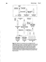
perfection, such molds could cost $100,000 or more. figure 2.17 is a summary of
product development thus far. Note that each stage builds upon the previous one. A
theme of the case study at the end of this chapter is that the CAD/CAM software
should gracefully and unambiguously make the transitions from one step to the next.
2.5.4
lime to a Finished Process Plan and the First
Production Run
When mechanical designers have finished the CAD designs and prototypes for a spe-
cific product, they want to see their real components manufactured quickly and with
fidelity.Process planning is the "bridge" from the rendered "virtual object" on the CAD
screen to the machined "physical object" leaving the machine shop and on its way back
to the designer.
Process planning involves several steps including (a) recognizing the features that
the designer created, (b) analyzing how the features overlap and intersect, (c) mapping
the geometry of these features to the capabilities and geometries of the "downstream"
manufacturing machines, (d) selecting appropriate fixtures and associated setup rou-
2.5 Question 4: How Fast Can the Product Be Delivered
(0)7
61
1,000
It's not
either/or
but a transition
Hard metal tool steel mold
/andPlasticinjeClion
Aluminum mold and
/Plaslif;injef;tion
Small batch mechinmg.or
/ casting,orRTVprocess
••/~AD optimize
/RPbySLA
/Find errors and "re·CAD"
/RPbYSLA
CAD
1,000,000
Time (months)
F1gure2.17 Product development cycle.
tines for the processing, (e) specifying the running parameters of the machinery,
(f) detailing the in-process and post-process inspection routines, and (g) providing a
quality assurance report that ties all the information together along with the part itself.
Even when the specific processes have been decided upon, there is still the selec-
tion of which machines will be used and how the parts will be routed through a flexible
manufacturing system (FMS). TIllsis the general domain of shop-level process selection
and production planning. The constraints that are introduced consider machine avail-
ability, raw material availability, and customer delivery times. Some of the techniques
needed to schedule the parts flow through the various machines are described by
Boume and Fox (1983), using constraint-directed reasoning; Cho and Wysk (1993),
using scheduling algorithms; and Adiga (1995) and Karnath, Pratt, and Mize (1995),
using object-oriented programming techniques.
These techniques address the scheduling of an "orchestra" of milling centers,
drilling machines, and lathes for metal production; or a series of lithography, deposi-
tion, and etching steps for IC wafer fabrication.
At a more detailed single-machine level, process planning needs to be done at
each individual machine. In today's factories the precise combination of which hole
needs to be drilled first and so on is still pretty much the domain of mature, skilled
machine operators who have been promoted to CNC programmers and
who write:
the
set up sheet, or the traveler, that goes along with allthe machine tool programs. The text
hy Wysk and associates (1998) provides a comprehensive review of the above topics.
2.5.5
lime to the First Customer
Simulation software isavailable to view the passage of parts through the factory on
different machines. Such simulation results speed up machinery setup and debugging
time. Also, if fixtures, dies, and tools can be reused from previous models, time is
62 Manufacturing Analysis: Some Basic Questions for a Start-Up Company Chap. 2
reduced. At this point, the first customer is on the horizon. Round-the-clock setup
and debugging work is almost certainly needed.
2.6 QUESTION 5: HOW MUCH FLEXIBILITY IFI7
In addition to production systems that fabricate very high
quality
products, at low
cost,
and with ultrarapid
delivery,
many strategic planners and economists point to
the need for
flexibility.
Publications from the United States and Europe (Agile, 1991; Black, 1993;
Cole, 1999;Greis and Kasarda, 1997;Anderson, 1997;Kramer, 1998)specificallyrefer
to the need for "agile manufacturing" systems that focus on "improving flexibility
and concurrence in all facets of the production process, and integrating differing
units of production across a firm, or among firms, through integrated software and
communication systems" (Agile, 1991).
Publications from Japan (Yoshio, 1994;Ohsono, 1995) express a similar view,
and the more recent
J.
D. Powers comparative surveys on automobiles indicate that
"now that others are closing the quality gap, the Japanese have to compete in other
areas" (see Rechtin, 1994;and the annual 1.D.Powers report series). Emphasis isthus
placed on these
combined
factors of quality, cost, delivery, and flexibility (QCDF).
The ability to react to smaller lot sizesand the quest for ultrarapid delivery are major
concerns, culminating in the possibility of a three-day car (Iwata et
al.,
1990).
In an ideal situation, once the various market sectors have been established,
production willsettle into a groove and be constantly refined and improved but with
no major upheavals. Unfortunately, in recent years, manufacturers have not been
able to rely on long periods of uninterrupted production because events in the world
economy have forced rapid changes inconsumer demand and the range of consumer
preferences.
Henry Ford's favorite aphorism-that his customers could have any color of
car they wanted as long as it wasblack-is in sharp contrast to today's range of con-
sumer preferences. This has led to the proposal by some academics that manufac-
turing can be built for "customized mass production." This sounds nice on first
hearing. However,for products like automobiles, the degree of customization can go
only so far for a given batch size and price point. Only hyperwealthy CEQs and
movie stars can get precise customization in products like automobiles.
Nevertheless, an ability to be prepared for any sudden market shifts is
becoming more of an issue.As new equipment is purchased, manufacturing compa-
nies must decide between hardware that is dedicated to only a few tasks and is thus
relatively inexpensive,and more costly but more versatile equipment that might per-
form unforeseen tasks in the future. The methodologies for analyzing capital expen-
ditures.retums-on-investment (ROI), and depreciations are given in many texts (see
Parkin, 1992).
These can be used to analyze the ROI for new machinery that has been identi-
fied asuseful and istherefore about to be purchased. However, since today's market
trends are so uncertain, such analyses do not help to predict the specific systems to
install in the first place.The hope isthat some of the engineering solutions presented
2.6 Question 5: How Much Flexibility (Fl7
63
later in this book will provide much more flexible machinery for only a modest
increase in cost (Greenfeld et al., 1989). In this way, the investment dilemma might
be less critical.
The preceding discussions emphasize that flexibility is a main challenge for the
continued growth of a new company. The main question is: Can a design and fabri-
cation system that is first set up to respond to one market sector be quickly recon-
figured to respond to the needs of another market sector, or even another product,
and be just as efficient?
Today, the answer to this question is "Probably not." For example, if a machine
shop is well equipped with lathes but has no vertical boring machines, there will be
a natural limit on achievable tolerances. It is unlikely that it will be able to suddenly
jump from truck transmissions to helicopter transmissions. And even in the reverse
scenario, if a shop has dedicated itself to precision boring,it is unlikely that the equip-
ment and the craftspeople will be able to be quickly redeployed in a cost-effective
manner to routine production procedures and less demanding tolerances; their com-
petitive advantage would be lost. These same comparisons can be made for semi-
conductor manufacturing. Manufacturers who are currently focusing on the
high-volume production of memory chips will not readily switch to application-specific
devices or vice versa. The general conclusion may be drawn that today's manufac-
turing tools-c-spccifically machine tools, robots, and manufacturing systems-are
still too dedicated to specific market sectors and are not flexible enough.
This general need for flexible, reconfigurable manufacturing systems was of
course a key aspect of CIM in its original conception. Merchant (1980) led a number
of industry forecasts between 1969 and 1971 that refined the details and needs of the
CjM
philosophy. However, these forecasts overestimated the rate at which flexible
manufacturing systems and related technology would be absorbed into factories.
During the 1970s and 1980s, machines exchanged "handshakes" when tasks were
completed. If these tasks were completed properly and on time, then a flexible man-
ufacturing system (FMS) continued to operate satisfactorily. However, if the
machines went seriously out of bounds, then the communications broke down and
too frequent human intervention was needed to make the FMS efficient. During this
era, the experiences of several research and development groups showed that the
inadequacy of cell communication software was probably the key impediment to the
industrial acceptance of CIM (Harrington, 1973; Merchant, 1980; Bjorke, 1979). Of
interest was that by the late 1980s, the review articles on CIM were advocating much
smaller FMSs of only three or four machines as the most efficient way of utilizing the
cell concept. All these trends suggested more sophisticated computer- and sensor-
based techniques at the factory floor, as described later.
2.6.1 Design for
flexibility
IRe use)
Design for flexibility in the automobile industry can payoff in a big way if there is
some reusability of fixture families. The automated assembly lines where the frames,
doors, and chassis are assembled with robots and welded together are obviously
intensely expensive. These are usually two-story-high lines as big as many football
fields where robots, fixtures, and alignment cradles bring the body components
84 Manufacturing Analysis: Some Basic Questions for a Start-Up Company Chap.2
together for welding and assembly. The intense cost of these lines is hard to picture
without a visit to a standard automobile plant. The key issue is to maximize the use
and reuse of these fixturing lines. If designers were allowed total freedom, each
vehicle in the family might require special tooling. This would not allow cost-effective
manufacturing. As mentioned earlier, this factor places an important responsibility
on the designer. In an ideal situation the newly designed component will be made on
existing factory-floor machinery, readily leading to an "off-the-shelf' automation
solution. In the best case, existing fixtures and even some parts of existing dies will
also be reused.
Some companies, those with smaller batch sizes, might use a mixed production
line.As one views such a line, several body styles go by:perhaps the mix is as simple as
regular sedans and station wagons,but the mixcan often be stretched beyond this to dif-
ferent cars of more or less the same size.With good design for multiple usability,many
of the hard fixtures and robots can be used for allthe differing vehicles in the family.
Also, with good cooperation between manufacturing and design, the existing
robots and fixtures might even be able to "upwardly constrain the vehicle design
space" for future vehicles. Therefore, viewed across several years and more than one
family of vehicles, automation costs are relatively lower per individual vehicle.
2.6.2 Concluding Remarks: Design Aesthetics versus
Manufacturing
Just to keep a proper perspective at the close of this subsection, it must be empha-
sized that design for manufacturability (or flexibility) has to be prudently applied
with the perceived end user constantly in mind. The Japanese articles concerned with
TQM (Yoshio, 1994; Iwata et ai., 1990;see Hauser and Clausing, 1988) increasingly
emphasize the more qualitative aspects of aesthetics as one of their next thrusts, even
though this is much more difficult to measure as a design objective.
At one extreme, a component that is destined to be buried deep in a car, a
washing machine, or a furnace does not need to look good. DFM and DFA methods
can be applied at every step in Figure 2.1.
At the other extreme, there willalways be a market for high-quality expensive
products such as the $300 polo shirt discussed in Section 2.4.10, a new Jaguar, or an
expensive Bang and Olfson music system. In these cases the buyer is actively seeking
style and luxury. Therefore, the design-Ior-manufacturability engineers cannot have
it all their own way, or a car might end up looking like a rectangular box on four
wheels: cheap, it's true, but hard to sell.
To conclude with personal observations, it isclear from visitstoTokyo and Kyoto
that wealthy Japanese people prefer a Mercedes Benz, a BMW, a Jaguar, or the large
Toyotas and Accuras. Not many American cars are seen on the streets, even in the
financial districts and embassy areas of Tokyo. One does see the occasional Cadillac,
some fully loaded Jeeps, and some of the newer Ford Mustangs, but not many.
The "Big Three" U.S. companies complain that the reason for this is that Japan
imposes trade barriers on
u.s.
vehicles. However, perhaps the real reason is that a
wealthy Japanese businessman wants a car with brando. This is a Japanese phrase
meaning "brand appeal." So, perhaps U.S. cars in Japan just don't have enough
2.7 Management of Technology
6.
brando at the present time. After all, Japan is swamped with other US. products that
do have
brando:
Levi's 501, McDonald's, Hollywood action movies, and CDs by
American musicians. And, inevitably, the Starbuck's Coffee shops in Tokyo are
swamped.
The moral of the story is that product design and product manufacturing have
art and irrational emotions lurking in their comers that design and manufacturing
engineers should not ignore. A product that can evoke the
aesthetic experience,
dis-
cussed in Chapter 1in the section called "The Art of Manufacturing," will always cap-
ture some of the market.
2.7 MANAGEMENT OF TECHNOLOGY
Chapter 1reviewed the art, technology,science, and business of manufacturing. During
the last 100years design and manufacturing have clearly moved from an
art/technology
endeavor to a
business/science
endeavor. Emphatically, in this new business/science
environment, being gifted in just the science and technology is not enough to win the
day.Specifically,U.S.manufacturing in the late 1980swas clearly in a panic. Basic indus-
tries such as semiconductors, automobiles, consumer electronics, and machine tools
were all losing out to international competitors.
Today, things do seem a lot better on all fronts. In "How the World Sees Us" the
New York Times boldly stated: "Our technology-c-computerized weapon systems,med-
ical scanners, the Intemet-sets the standard to which developing countries
aspire."
No single miracle has happened, but steady progress has occurred in:
• Creativity in design and manufacturing
• Quality assurance and control of basic manufacturing methods
• Downsizing companies to be more efficient
• Global commerce
• Internet commerce
The fact that some of our international competitors did not fare too well and strug-
gled with unfavorable currency exchange rates in the late-1990s also made it easier
for U.S.companies to compete.
At the time of this writing, the challenge for the future is to keep this real
growth going. For a few years, U.S.manufacturers were chasing their Pacific Rim and
European competitors and even enjoying the athletic-event psychology of "coming
from behind." Staying up with the front-runners or, better still,being ahead requires
an extra degree of creativity and commitment.
Similar to the above list, perhaps some specific areas for continued creativity
include:
• Further exploiting global markets through Internet commerce.
J
Tire New York 1imes Magazine,
June
8, 1997, 37-83.
66 Manufacturing Analysis: Some BasicQuestions for a Start-Up Company Chap.2
• Focusing on complex systems, specifically developing CAD/CAM techniques for
the electro/mechanical/hiological products that are on the horizon.
• Continuing with the time-to-market awareness, balanced by aesthetic creativity.
• Continually striving for the 6-sigma quality goal.
• Creating an organization that can cope and even thrive on change. For example,
all industries-cfrom semiconductors, to machine shops, to steel mills-are being
told to be more environmentally conscious. Being so, and yet still being competi-
tive with other countries that might care much less about issues such as pollution
or industrial safety, challenges manufacturers to be especially creative and effi-
cient.
• Responding proactively to government funding opportunities, public policy, and
federal regulations that impact all industries at some level. For example, a project
such as the originallntemet was launched more than 25 years ago by the Defense
Advanced Research Project Agency (DARPA), and it has continued to be uur-
tured by the National Science Foundation (NSF).The MOSIS (2000) story is sim-
ilar.It can thus be reasonably argued that much of the wealth of Silicon Valley in
northern California and Route 128 near Boston had its birthplace in projects such
as these. Companies that are willing to understand the constraints and then
cosponsor this type of federally funded research can benefit greatly. However,
reaching consensus can often be frustrating and time-consuming, as seen recently
in the regulations surrounding tho telecommunications industry. (On another
constraining note in biotechnology, the FDA-supervised drug trials do impose a
long period of time between initial research and development (R&D) invest-
ments and the marketplace. Perhaps for this reason, many small biotechnology
start-ups are bought out by the deep-pocket pharmaceutical companies.)
• The initial time-to-market of a new product and the ongoing delivery time of an
established product are ongoing themes of this book. The integration issues that
will be discussed around design, planning, and fabrication are obvious areas to
focus on technically. In particular, new hardware and software environments
allow the connections between design, planning, and fabrication to be simplified.
Particular benefits include the reduction of the time taken to obtain the first pro-
totype of a designed object, whether it is a chip or a computer casing. New tech-
niques and standards for distributed software systems also provide a more
information-rich dialogue between the design function and the manufacturing
function. The ability to rapidly obtain an initial prototype allows designers to
assess the aesthetic aspects of a design. It also allows a preliminary analysis of how
a single object in a subassembly will interact with mating components, and finally
allows some preliminary decisions to be made on the future manufacturing
methods for the component. The benefits of obtaining an initial physical proto-
type are seen to embrace both the component itself and the way in which the
component will be produced. The ability to evaluate both the product and the
process by which it will be made is an essential concept in concurrent or simulta-
neous engineering.
Although there will be many new trends and unexpected disturbances, one
basic business goal will remain constant the winners will be those who design, plan,
2.8 References
67
and manufacture a high-quality product at the right price and get it to market first. To
address this need, Chapter 2 has considered some general principles of manufacturing
analysis in the context of four parameters: quality,cost,deiivery, and flexibility (QCDF).
Generic approaches for quality assurance methods were also reviewed. The chapter
also discussed some guiding subprinciples for process selection in mechanical manu-
facturing.
2.6 REFERENCES
ACIS. 1996. ACIS technical overview, AC1S geometric modeler, programming manual. ACIS 3D
Toolkits. Boulder, CO: Spatial Technology Inc
Adiga, S. 1993. Ubject oriented software for manufacturing systems. London: Chapman
&
Hall.
Agile Manufacturing Enterprise Forum. November 1991. An industry led view of 21st century
manufacturing enterprise strategy; 2 vols, Bethlehem, PA: Lehigh University.
Anderson, D. M. 1997. Agile product development for mass customization. Burr Ridge, ILL: Irwin
Publishers.
Ashley, S.Apri11991. Rapid prototypingsystems. Mechanical Engineering Magazine, ASME, 34-43.
Au, S.,and P. K. Wright. 1993.A comparative study of rapid prototyping technology. In Intelligent
concurrent design: Fundamentals, methodology, modeling and practice, ASME DE 66:73 82.
Ayres, R.
0.,
and S.M. Miller. 1983. Robotics:Applications and social implications. Cambridge,
MA: Ballinger Press.
Bjorke.O. 1979. Computer aided part manufacturing. Computers in Industry 1,no.l: 3-9.
Black, 1.T. 1991. The design of a factory with a future. New York: McGraw-Hili
Boothroyd,
0.,
and P.Dewhurst. 1999. DFMA Software, on CD from the company, or contact
<www.dfma.com>
Bourne, D. A., and M. S. Fox. 1983.Autonomous manufacturing:Automating the job shop. Com-
puter Magazine, IEEE, 17, no. 9.
Chang, T. 1990. Expert process planning for manufacturing. Reading, MA: Addison-Wesley.
Cho, H., and R. A.Wysk. 1993. A robust adaptive scheduler for an intelligent workstation con-
troller. International Journal of Production Research 31, no. 4: 771-789.
Cole, R. E.I999. Managing quality fads: How American business learned to play the quality game.
New York and Oxford: Oxford University Press.
Cutkosky, M. R., and 1.M. Tenenbaum. 1990. A methodology and computational framework for
concurrent product and process design. Mechanism and Machine Theory 25, no. 3: 365-381.
DeVor, R. E., T. H. Chang, and 1. W. Sutherland. 1992. Statistical quality
control:
New York:
MacMillan Publishing Co.
Dewhurst, 1'.,and G. Boothroyd. 1988. Early cost estimating in product design. Journal of Manu-
facturing Systems 7, no. 3: 183-191.
Dowling, N. E. 1993. Mechanical behavior of materials. Upper Saddle River, NJ: Prentice-Hall.
DTM Corporation. 1993. Selective laser sintering. Product Information Bulletin 1, no 1.
Esawi,A. M. K., and M. F.Ashby.1998a. Cost-based ranking for manufacturing process selec-
tion. In Proceedings of the Second International Conference on Integrated Design and Manu-
facruring Mechanical Engineering (IDMME 1998). Compiegne, France 4: 1001-1008.
Esawi,A. M. K., and M. F.Ashby.I998b. The development and use of a software tool for selecting
manufacturing processes at the early stages of design. In Proceedings of the Third Biennia/World
Conference on Integrated Design and Process Technology (IDPT). Berlin, Germany 3: 210-217.
88 Manufacturing Analysis: Some Basic Questions for a Start-Up Company Chap. 2
Fmnie,I. (Chair of Committee). 1995. Unit manufacturing processes. Washington, D.e: National
Academy Press.
Garvin, D. A. 1987. Competing on the eight dimensions of quality. Harvard Business Review
(November-December): 101-109.
Greenfeld, I., F. B. Hansen, and P.K. Wright. 1989. Self-sustaining, open-system machine tools.
In Proceedings of the 17th North American Manufacturing Research Institution 17: 281-292.
Greis, N. 1':, and
I
D. Kasarda. 1997. Enterprise logistics in the information era. California
Management Review 39, no. 3: 55-78.
Harrington,
I
1973. Computer integrated manufacturing. New York: Industrial Press.
Hauser,
I
R., and D. Clausing. 1988. The house of quality. Harvard Business Review
(May-June): 63-73.
Hazelrigg, G. A. 1996. Systems engineering: An approach to information-based design.
Upper Saddle River, N.J.: Prentice-Hall International Series in Industrial and Systems
Engineering.
Hertzberg, R. W. 1996. Deformation and fracture mechanics of engineering materials. New
York: John Wiley.
House, C H., and R. L. Price. 1991. The return map.Tracking product teams. Harvard Business
Review (January-February): 92-100.
Inouye, R., and I': K. Wright. 1999. Design rules and technology guides for Web-based manufac-
turing. The Design Engineering Technical Conference (DETC) on Computer Integrated Engi-
neering, Paper Number DETC'99/CIE-9082, Las Vegas.
Iwata, M., A. Makashima, A. Otani, 1.Nakane, S. Kurosu, and T. Takahashi. 1990. Manufac-
turing 21 report: The future of Japanese manufacturing. Wheeling, IL: Association of Manu-
facturing Excellence.
Jacobs, P. F. 1992. Rapid prototyping and manufacturing: Fundamentals of stereolithography.
Dearborn, Ml: Society of Manufacturing Engineers Press.
Jacobs, P. F.1996. Stereolithography and other RP&M technologies. Dearborn, MI: Society of
Manufacturing Engineers Press.
Jones, R., S. Mitchell, and S. Newman, 1993. Feature based systems for the design and manu-
facture of sculptured products. International Journal of Production Research 31, no.
6: 1441-1452.
Kalpakjian, S. 1997. Manufacturing processes for engineering materials. Menlo Park, CA:
Addison Wesley. (See in particular Chapter 15).
Kamath, M., 1.Pratt, and
I
Mize, 1995. A comprehensive modeling and analysis environment
for manufacturing systems. In Proceedings of the 4th Industrial Engineering Research Confer-
ence, 759-768. Also see lcocim.
Kamath, R. R., and 1.K. Liker, 1994. A second look at Japanese product development.
Har-
vard Business Review (Reprint Number 94605).
Kochan. D. 1993. Solid freeform fabrication. Amsterdam: Elsevier Press
Kramer, B. M. 1998. Proceedings of the 1998 NSF Grantees Design and Manufacturing Con-
ference. Monterrey, Mexico. See annual volumes of this conference. Arlington, VA: National
Science Foundation.
Machinint-: Data Handbook. 1980. 3d ed. 2 vols. Cincinnati, OH: Institute of Advanced Manu-
facturing Systems (lAMS).
Magrab, E. B. 1997. Integrated product and process design and development. Boca Raton and
New York: eRC Press.
Mead, C, and L. Conway. 1980. Imroduction to VLSI systems. Reading,MA:Addison Wesley.
2.8 References
69
Merchant, M. E. 1980.The factory of the future-Technological aspects. In Towards the Factory of
the Future.
PED I: 71-82 New York-American Society of Mechanical Engineers.
Moore,G.Al995.lnsidethetomado. New York: Harper Business.
MOSIS.2000. University of Southern California's
tntormasion
Sciences Institute-The MOSIS
VLSI Fabrication Service, lmosisi
NSF. 1993. Agile Manufacturing Initiative, program solicitation, National Science Foundation's
Directorate for Engineering.
Ohno, T. 1988. Toyota production system: Beyond large scale production. Portland, OR: Pro-
ductivityPress.
Ohsone, T. 1995. Charting Japanese industry. London and New York: Cassell Publishers.
Ostwald, P E 1988. American Machinist cost estimator, 4th ed. Cleveland, OH: Penton Education
Division.
Parkin, M. 1990. Economics. Reading, MA: Addison Wesley.
Peters, T. 1., and R. H.
waterman.
1982. In search of excellence: Lessons from America's best-ron
companies. New York: Harper and Row.
Poppel, H. L., and M. Toole. 1995. The bleeding edge of information technology. The Red Herring
Magazine, (June):82-S6.
Pressman, R. S., and 1.E. Williams.
1m.
Numerical control and computer-aided manufacturing.
New York: Wdey and Sons.
Queenen,A 1979. The modular approach to productivity in flexible manufacturing systems. Tech-
nical Report 79-824. Dearborn, MI:The Society of Manufacturing Engineers.
Rechtin, M. 1994. "Europeans roar to no. 2 in CSL Automotive News, (July 11): 59.
Sachs, E., M. Clma.J, Bredt,A Curodeau, T. Fan, and D. Brancazio.1992. CAD casting: direct fab-
rication of ceramic shells and cores by three dimensional printing. ASME Manufacturing Review
5,no.2
Sands, R. L 1971. Sel"rtinn nf proresses for the manufacture of small components, in cornpeti-
tive methods off arming. (103-112). lSI Publication Number 138. London:The Iron and Steel
Institute.
Schey,1. A. 1999. Introduction to manufacturing processes. New York: McGraw-HilL
Senge. P.,A Kleiner, C. Roberts, R. Ross, and R Smith. 1994. The fifth disciplinefieldbook. New
York: Doubleday Books.
Shah.J, I. 1991.Assessment of features technology. Computer Aided Design 23, no. 5: 331-343.
Smith, G. W. 1973. Engineering economy: Analysis of capitol expenditures. Ames: Iowa State Uni-
versityPress.
Suh, N. P. 1990. Principles of design. New York: Oxford University Press.
Sungertekin, U. A, and H. B.Voelcker, 1986. Graphic simulation and automatic verification of
machining programs. In Proceedings of the 1986 IEEE Conference on Robotics and Automa-
tion, 156-165.
Tadikamalia, P R. 1994. The confusion over six-sigma quality. Quality Progress, 83-85.
Thomas, R. 1. 1994. What machines can't do. Berkeley, Los Angeles, London: University of Cali-
fornia Press. See in particular Chapter 7, "The Politics and Aesthetics of Manufacturing," 246-258.
Thuesen, H.
0.,
W. 1. Fabrycky, and G. 1.Thuesen. 1911. Engineering economy. Englewood Oiffs,
N.I.:Prentice-Hall.
Toye. C; M. R. Cutkosky, L.1. Leifer, M. Tenenbaum, and 1.Glicksman. 1994. SHARE: A method-
ology and environment for coUaborative product development.lntemational Journal of InteUigent
Systems 3, no. 2: 129 153.
70
Manufacturing Analysis: Some Basic Questions for a Start-Up Company Chap. 2
Ulrich, K. T., and S. D. Eppinger. 1995. Product design and development. New York: McGraw-HilI.
Urabe, K.,and P.K. Wright. 1997. Parting planes and parting directions in a CAD/CAM system for
plastic injection molding. 1997 ASME Design for Manufacturing Symposium. The Design Engi-
neeringTechnica.l Conferences, Sacramento, CA,
Wang,
F c.,
and P. K. Wright. 1998a. Web-based design tools for a networked manufacturing
service. Paper presented at the 1998ASME DesignTechnical Conference,Atlanta,GASeptember
13-16.
Wang, F C, and P. K. Wright. 1998b. Internet-based design and manufacturing on an open archi-
tecture machining center. Paper presented at the 1998 Japan-USA Symposium on Flexible
Automation, Ohtsu, Japan, July 13-15.
Wang, F-C, and P.K. Wright. 1998. Collaborative design: A case study on InfoPad, a wireless, net-
worked computer. Anaheim, CA:The International Mechanical Engineering Congress and Expo-
sition.
Webster'~New Wnrld College Dictionary.
1999. Foster City, f:A: TOG Rooks Worldwide.
Weiss, L., E. Gursoz, F.B. Prinz, P.Fussel, S.Mahalingam, and E. Patrick. 1990. A rapid tool manu-
facturing system based on stereolithography and thermal spraying.ASME Manufacturing Review
3,no.l.
Weiss, L. E., and F. B. Prinz. 1995. Shape deposition processing. Paper presented at the NSF
Workshop II on Design Methodologies for Solid Freeform Fabrication, Pittsburgh, PA, June
,
Weiss, L. E., R. Merz, F. B. Prinz. G. Neplotnik, P. Padmanabhan, L. Schultz, and K.
Ramaswami. 1997. Shape deposition manufacturing of heterogeneous structures. SME
Journal of Manufacturing Systems 16: 239-248.
Weiss, L. E., and E B. Prinz, 1998. Novel applications and implementations of shape deposi-
tion manufacturing. Naval Research Conference.
Wright, P. K., D.A Bourne, 1.P. Colyer, G. S. Schatz, and 1.A. E. Isasi. 1982. A flexible man-
ufacturing cell for swaging. Mechanical Engineermg, 76-83.
Wright, P. K., and D. A. Bourne. 1988. Manufacturing intelligence. Reading, MA: Addison
Wesley.
Wysk, R. A., T. C. Chang, and H. P.Wang. 1998. Computer aided manufacturing, 2d ed. Pren-
tice-Hall.
Yoshio, T.1994. Japan's competitiveness in industrial technology. Journal of Japanese Trade
and Industry 13, no. 4: 8-10.
2.9 BIBLIOGRAPHY
Barr, A., and E. Feigenbaum. 1981. The handbook: of artificial intelligence, 1-3. Lus Altos.
CA: Heuristech Press, Stanford, and William Kaufmann Inc.
Bouthruyd,
0.,
P. Dewhurst, and W. Knight, 1994. Product design for manufacture and
assembly. New York: M. Dekker.
Chanan, S. 1994. Concurrent engineering: Concepts, implementation and practice, 1st ed.
Edited by Chanan S. Syan and Unny Menon. London, New York: Chapman
&
Hall.
Chang, T. 1990. Expert process planning for manufacturing. Reading, MA: Addison-Wesley.
Cook, N. H. 1966. Manufacturing economics. In manufacturing analysis, 148-159, Reading,
MA: Addison Wesley.
2.10 Case Study
71
Corbett,1. 1991.Design for manufacture: Strategies, principles, and techniques. Edited by
John Corbett et al. Addison-Wesley Series in Manufacturing Systems. Reading, MA:
Addison-Wesley.
DeGarmo, E. P.,1.T.Black,and R.A. Kohser.1997.Materials and processes in manufacturing,
8th ed. Upper SaddleRiver,NJ:Prentice-Hall.
El Wakil,S.0.1998. Processes and design for manufacturing. Boston:PWSPublishers.
Groover.M.P.1996.Fundamentals of modern manufacturing. Prentice-Hall.
Koren,Y, F.Jovane,and G. Pritschow,1998.Open architecture control systems: Summary of
global activity. Institute for IndustrialTechnologiesandAutomation.
Peterson,1.1997.Finelinesfor chips.Science News (8 November):302-303.
2.10 CASE STUDY
2.10.1 TouchChipTM:A Fingerprint Recognition Device
Ibis case study presents the product development process of a novel fingerprint
recognition device. Some 250 prototypes were produced as evaluation kits for mar-
keting purposes. Some key points that may be learned in the case study include:
• A "naked printed circuit board" is not the best marketing device.
• A single prototype in SLA, SLS, or FDM is only the starting point for a short
prototype run (250) and then for real production (many thousands).
• A clear focus on "who is the customer" significantly influences the required
batch size decision. This in tum determines the best manufacturing processes
and also has an effect on the CAD tool that is chosen to create the design.
• If the conceptual design phase and the fabrication phase are concurrently con-
sidered at the beginning of the project, time-to-market is improved.
•The aluminum tooling for a new product was created with an integrated
design-to-machining system. The "clean interfaces" between various modules
for CAD, process planning, and fabrication also created more reliable and
faster time-to-market. The system's front end was a set of design tools that
encapsulated machining knowledge for checking manufacturability. This valid
design was passed to an automated process planning module through a clean,
unambiguous interchange format that eliminated unnecessary personal con-
versations between the designers and process planners. The process plan was
then sent to an open-architecture three-axis CNC milling machine, which exe-
cuted standard G
&
M codes for machining.
2.10.2 "Who Isthe Customer?": Manufacturing Analysis
and Conceptual Design
The Touchr.hiptv is a small sensor manufactured by ST Microelectronics. It uses
techniques based on capacitance variation for fingerprint recognition. Other finger-
print recognition units on the market use optical devices, but this is a "silicon solu-
tion." The TouchChip can be used for a variety of applications that might include
72
Manufacturing Analysis: Some Basic Questions for a Start-Up Company Chap. 2
door entry, passwords for computers, replacing PINs for bank cards, and credit card
verification.
The project began with the "naked" chip-an-board device shown in Figure 2.18.
However, it was quickly realized that potential customers-typically computer
peripheral makers-would be more impressed if a good prototype of a packaged
unit could be created. Therefore, the goal was to create a small batch of product pro-
totypes (about 250 assemblies) as evaluation kits for potential customers in the
recent COMDEX Trade Show at Las Vegas. The entire project encompassed con-
ceptual product design through prototyping to final production and packaging. The
final product is shown here, and the manufacturing analysis follows.
2.10.2.1 Electronic Components
The device shown is ST Microelectronics's TouchChip STFP2015-50. It has a 20
mm x 15 mm surface with a 384 x 256 sensor array with approximately 100,000 indi-
vidual sensors. The TouchChip utilizes a feedback capacitive sensing scheme. The
sensing cell detects the distance between the skin and the sensor and identifies the
presence of ridges and valleys.An array of sensing cells is used to sample the finger-
print pattern. The chip architecture and schematic diagram for the sensing cell are
shown in Figure 2.19. The chip is manufactured in a 0.7 micron two metal-layer
CM OS manufacturing process. A special coating protects the device from contam-
ination, scratching, and electrostatic discharge. The completed chip also has a stan-
dard connection through external cable to the serial ports of computers (Table 2.6).
2.10.2.2 Mechanical Package
The fabricated mechanical package holds the above electronic components (Figures
2.20 and 2.21).It also supports the user's index finger, when its tip is resting and slightly
pushing on the sensing window.The conceptual prototype is thus a mouselike enclosure
I1pre 1.18 TouchChip sensor and
electronics.
2.10 Case Study
TABLE
2.8 Details of the Device
73
Sensorsurlace
Module dimension
Sensor array
Capture rate
Data interface
Resolution
Pix<l
Power
Integrated submodules
2Ommx15nun
35 nun x 35 nun x 5 nun
384
x
256
lOfrarnesisec
8 bit parallel data interface
SOO+DPI
SO-micron
<200mW@5Volts
A-to-D converter, biases, on-board oscillator, and crystal
Flpre
2.ZI Integrated unit as a
password entry for a standard machine.
FlgureZ,19 Thesensor.
Mel~llplates
Finger
Horizontal scanner
IA~r
TIming
control and
references
r;:;;;-
<It
Features