21st Century Manufacturing Episode 1 Part 2 docx
Bạn đang xem bản rút gọn của tài liệu. Xem và tải ngay bản đầy đủ của tài liệu tại đây (578.53 KB, 20 trang )
,.
Manufacturing: Art, Technology, Science, and Business Chap. 1
Thus, in the 19905,the best companies extended concurrent engineering
and TQM to a higher level. This meant a "seamless" connection, all the way from
factory floor manufacturing to the desires of the consumer. While this may seem
obvious and sensible today, the "old" (certainly pre-1980) factory mentality was
mostly focused on getting products out the door and leaving things to a distant
marketing organization to make the link to the customer. This is not so today,
and this section of Chapter 1 focuses on business issues and manufacturing-in-
the-large.
These broader views are shown on the right of Figure 1.2.
Open-architecture
manufacturing
and
agile manufacturing
were thus new paradigms that permeated the
19OOs.These emphasized quickly reconfigurable enterprises that could respond to
the new customer demands of"delivery, quality,and variety" (Greenfeld et al.,1989;
Goldman et at, 1995;Anderson, 1997).
By the mid-1990s,Internet-based manufacturing was thc natural extension of
these paradigms, emphasizing the sharing of design and manufacturing services on
the Internet (Smith and Wright, 1996).
The availability of the Internet, videoconferencing, and relatively convenient
air travel seem to pave the way for increased global commerce. Large business
organizations canbe split up but then orchestrated over several continents perhaps
to take advantage of excellent design teams in one country and low-cost, efficient
manufacturing teams in another. But in fact, for a variety of cultural and economic
reasons, industrial growth has always been dependent on situations where "large
businesses are distributed." This was just as true in the year 1770when cotton from
Georgia in the United States wasshipped to Bradford in England for manufacturing
into garments and then exported to an expanding population throughout the
increasingly global British Empire. It was still true in the year 1970.just before the
creation of the Internet: product design in the United States and the use of cheaper
"offshore manufacturing" was a standard practice. In the 21stcentury, withthe World
Wide Weband videoconferencing, there is the
potential
for much faster exploitation
of advanced design studios in one location and cheap labor in another. Nevertheless,
clear communications-first, between the customer and the designer, and second,
between the designer and the manufacturer-remain vital for realizing this potential
and obtaining fast time to market. In later chapters of the book, examples
win
show
that those companies that beat their competitors in launching the next chip, cell
phone, or any consumer product will usually gain the most profit (see Ulrich and
Eppinger, 1995). .
Enterprise integration
thus appears in the fifth circle of Figure t.a.This term is
actually the idea of concurrent engineering carried to a much larger scale and cov-
ering the whole corporation. The key requirement is the integration of all the divi-
sions of a
manufacturing-in-the-large
enterprise. To reiterate, before 1980,Taylorism
created competitiveness rather than cooperation between these various divisions
(Cole, 1999).The more 21st century approach must involve the breaking down of
barriers between people and subdivisions of an organization so that the whole of the
enterprise can share problems openly,work toward shared goals,define shared pro-
ductivity measures, and then share the dividends equally.Time to market will then
1.6 Summary
15
benefit from this integrated design and manufacturing approach. This is one central
message of this book.
Beyond such intercorporation trust comes the possibility of agreements with
outside corporations. These agreements might spring up for a temporary period to
suit the commercial opportunity at hand. This more ephemeral version of the old
style monolithic business is called the virtual corporation. Nishimura (1999) argues
that a successful 21st century virtual corporation must continue to rely on the core
competency skills of each player, but at the same time, each participant must become
more experienced in partnering skills.
Thurow (1999) goes further and argues that "cannibalization is the challenge
for old business firms." It means that older well-recognized companies must now
fragment into smaller business divisions. These will interact tightly for certain busi-
ness ventures but then disband when their usefulness is over.
Open-architecture manufacturing, agile manufacturing, Internet-based manu-
facturing, and the virtual corporation all sound exciting. However, it does not take
much imagination to look at Figure 1.2 and realize that a new buzzword or phrase
will arrive soon. The reader is left to fill in the question mark. Perhaps the most
important thing, emphasized in Figure 1.2,is that each era builds upon the previous
one, and that under no circumstances should the organizational sciences built around
total quality management be forgotten. New engineering science technologies, such
as the Web, offer new ways of creating products and services, but efficiency and in-
process quality control in basic manufacturing will always be mandatory.
1.6 SUMMARY
By reviewing the art, technology, science, and business aspects of manufacturing, it
can be concluded that the activity of manufacturing is much more than machining
metals or etching wafers: manufacturing is an extended social enterprise. In the last
250 years, people have been dramatically changed by the advances in manufacturing.
Society has moved from an agrarian society, to handcrafts in cottage industries, to the
operation of machinery in factories, to computer automation/robotics (and all its
associated software writing and maintenance), and finally to telemanufacturing by
modem and the Web.
Gifted philosophers such as Marx and Maslow have noted that people actually
prefer to work rather than do nothing. But they want to get recognition for their
labors beyond a paycheck. In the early transitions described in Section 1.3,up until
the 1950s,craftsmanship often lost out to mass production and the dehumanization
of work. Today, by and large, people are not inclined to work in dangerous factory
situations or sit in a sea of cubicles carrying out monotonous word processing tasks
just for the paycheck.
As the futurist Naisbitt says, people want "high-tech high-touch," meaning
all the modern conveniences of life with a softer approach. Thus, once people
have enough money, they strive to re-create their jobs, to make them more inter-
esting, or to reeducate themselves for a more intellectually rewarding job. In
,.
Manufacturing:
Art
Technology, Science, and Business Chap. 1
today's corporations, this generally means moving off the factory floor. Initially,
a person's reeducation might lead to a position in machinery diagnostics and
repair or in the organization of production. In time, such a position might grow
into general management, personnel, and business oriented decision making. It
is likely that for several more decades, a
combination of people and partial
automation solutions will be seen on the factory floor. Today, the cost-effective
solution is to use mechanized equipment for, say, moving pallets of printed cir-
cuit boards through a reflow solder bath but to concurrently use human labor for
inspection, monitoring, rework, and the occasional corrective action,
Despite this partial-automation/partial-human situation, the long-term trend is
to invest in sophisticated capital equipment that can work completely unattended by
humans. This has always been the stated goal of computer integrated manufacturing
(Harrington, 1973;Merchant, 1980).
This leaves the people to work with knowledge issues. The trends in both Fig-
ures 1.1 and 1.2 from left to right emphasize this change from Taylor's "hired hands"
to "knowledge workers"-a term first coined by Peter Drucker in the 19408.For
many industries, there is also a shift in balance from capital-intensive machinery to
software and corporate knowledge. Many top managers are being forced to rethink
the way their organization functions. Indeed the role of "management" in and of
itself isbeing reevaluated.This is especially true in newer start-up companies where
the culture is informal and youth oriented.
Drucker (1999) reexamines the foundations of management within this new
context. He argues that management policy within a firm should focus on "customer
values and customer decisions on the distribution of their disposable income." This
is consistent with the themes at the beginning of Chapter 2 and throughout this book,
Without a clear answer to the question "Who is the customer?" product develop-
ment, design, prototyping, and fabrication may be misguided.
In the 21st century, providing an environment that promotes creativity and
flexibility will continue to be the social trend-a rather different emphasis than that
of the early "time-and-motion studies" at the beginning of the 20th century! Fur-
thermore, in contrast to working for one company for a lifetime, new graduates see
themselves asfree agents,namely, gaining more skills by moving from one company
to another every one to three years (see Jacoby, 1999;Cappelli, 1999),
Given these trends, this introductory Chapter 1 ends with the question, "Will
there be manufacturing, and willpeople work in the year 2100?"
The answer is probably "No" to anything that looks like manual labor, but
"Yes" to collective enterprises where people design, plan, and install automation
equipment and make things for consumers. And probably, those consumers (in the
outer circle of Figure 1.4) will need or want pretty much the same things they have
always needed or wanted since before the Greeks and the Romans: good health, nice
food, happy relationships, attractive clothes, safe and comfortable housing, as-fast-
as-possible transportation, and gizmos for entertainment.
We might teleconunute andtelemanufacture: one day we might, as admired on "Star
Trek," even teletransport but the human soul willprobably stay pretty earthy and basic.
1.7 References
17
1.7 REFERENCES
Anderson, D. M. 1997. Agile product development for mass customil.ation. Chicago: Irwin
Publishing.
Armarego, E. 1.A., and R. H. Brown. 1969. The machining of metals. Englewood Cliffs, N.J.:
Prentice-Hall.
Ayres, R.
u.,
and S. M. Miller. 1983. Robotics; applications and social implications. Cam-
bridge, MA: Ballinger Press.
Bjorke,o. 1979. Computer aided part manufacturing. Computers in Industry 1, no. 1: 3-9.
Bralla,1. G., Ed. 1998. Design for manufacrurabiliry handbook, 2nd ed.New York: McGraw-
Hill.
Cappelli, P. 1999. Career jobs are dead. California Management Review 42, no. I: 146-167.
Cole, R. E. 1999. Managing quality fads; How american business learned to play the quality
game.
New York and Oxford: Oxford University Press.
Drucker, P. F. 1999. Management challenges for the 21st century. New York: HarperCollins
Publishers.
Engelberger,1. F. 1980. Robotics in practice. New York: Amacom Press.
Goldman,
s.,
R. Nagel, and K. Preiss. 1995.Agile competitors and virtual organizations. New
York: Van Nostrand Reinhold.
Greenfeld, 1, F. B. Hansen, and P. K. Wright. 1989. Self-sustaining open system machine
tools. In Transactions of the 17th North American Manufacturing Research Institu-
tion,
304-310.
Harrington, 1. 1973. Computer integrated manufacturing. New York: Industrial Press.
Jacoby, S. M. 1999. Are career jobs headed for extinction? California Management Review
42, no. 1: 123-145.
Leachman, R. C, and D. A. Hodges. 1996. Benchmarking semiconductor manufacturing.
IEEE Transactions on Semiconductor Manufacturing 9, no. 2: 15H-169.
Macher,!. T.,D. C. Mowery, and D. H. Hodges. 1998. Reversal of fortune? The recovery of
the U.S. semiconductor industry. California Management Review 41. no. 1: 107-136.
Berkeley: University of California, Haas School of Business.
Merchant, M. E. 1980. The factory of the future-technological aspects. Towards the Fac-
tory of the Future, PED-Vol. 1,71-82. New York: American Society of Mechanical Engi-
neers.
Nishimura, K. 1999. Opening address. In Proceedings of the 27th North American Manu-
facturing Research Conference. Berkeley, CA.
Pfeiffer, J. E. 1986. Cro-megnon hunters were really us: working out strategies for survival.
Smithsonian Magazine,
75-84.
Plumb, 1. H.I965. England in the eighteenth century. Middlesex, England: Penguin Books.
Rosenberg, N. 1976.
Perspectives on technolOGY'
Cambridge, England; Cambridge Univer-
siry Press.
Schonberger, R. 1998. World class manufacturing; The next decade. New York: Free Press.
Smith. C. S., and P. K. Wrigbt.1996. CyberCut: A World Wide Web based design to fabrica-
tion tool. Journal of Manufacturing Systems 15, no. 6: 432-442.
Taylor, F. W. 1911. Principles of scientific management. New York: Harper and Bros.
,.
Manufacturing: Art, Technology, Science, and Business Chap. 1
Thomsen.B. G., and H. H. Thomsen. 1974. Early wire drawing through dies. Transactions of
the ASME, Journal of Engineering for Industry
96, Series B, no. 4: 1216-1224. Abo see
Thomsen, E. G. Tracing the roots of manufacturing technology: A monogram of early man-
ufacturing techniques. Journal of Manufacturing Processes. Dearborn, Mich.: SME.
Thurow, L.1999. Building wealth. The Atlantic Monthly 283, no. 6: 57 69.
Ulrich, K. T., and S. D. Eppinger. 1995. Product design and development. New York: Mcrjraw-
Hill.
Wood, A. 1963. Nineteenth century Britain. London: Logmans.
WIight,P. K.,and D.A. Boume.1988. Manufacturing intelligence. Reading, MA;Addison Wesley.
1.8 BIBLIOGRAPHY
1.8.1 Technical
Compton, W. D. 1997. Engineering management. Upper Saddle River, NJ.: Prentice-Hall.
Cook, N. H. 1966. Manufacturing analysis. Reading, MA: Addison Wesley.
DeGarmo, E. P., J. T. Black, and R. A. Kohser, 1997. Materiah and processes in manufacturing,
8th ed. New York: Prentice Hall.
Groover, M. P. 1996. Fundamentals of modern manufacturing. Upper Saddle River, NJ: Pren-
tice-Hall.
Jaeger, R. C.1988. Introduction to microelectronic fabrication. Reading, MA:Addison Wesley
Modular Series on Solid State Devices.
Kalpakjian, S. 1997, Manufacturing processes for engineering materials. 3rd ed. Menlow Park,
CA: Addison Wesley Longman.
Koenig, D. T. 1987. Manufacturing engineering: Principles for optimization. Washington, New
York, and London: Hemisphere Publishing Corporation.
Pressman, R. S., and 1 E. Williams. 1977. Numerical control and computer-aided manufacturing.
New York: Wiley and Sons.
Schey, lA.I999. Iruroduction to manufacturing processes. New York: McGraw-Hili.
Womak,1. P, D. T. Jones, and D. Roos. 1991. The machine that changed the world. New York:
Harper Perennial.
1.8.2 Social
Sale, K.1996. Rebels against the future: the Luddites and their war on the industrial revolution.
Reading, MA: Addison Wesley.
1.8.3
Recommended
Subscriptions
TIle
&ollomist,
<WWw.eronombt.com>.25St.JamesSt .•LondonSWlAIHQTIllsoIlenindude. s
special "pull-out sections" on "high technology": for example, see the June 20, 1998, copy that con-
tains "Manufacturing" and the June 26, 1999, copy that contains "Business and the Internet."
Fast Company, <www.faskompany.com>.77NorthWashingtonSt Boston.MA. 02114-1927.
The
Red Herring,
<www~m>, Redwood OtY,CA,FJipside Communications,
Scientific American, <>.415 Madison Ave., New York, NY, 10017-1111.
Wired <www.wIred.com>.5203rdSt .•Srd Flcor.San
Franoisco.Cg.,
94107-1815.
1.10 Review Material
"
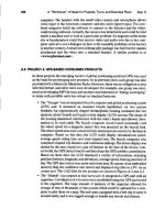
1.9 CASE STUDY: "THE NEXT BENCH SYNDROME"
Many of the chapters in the book contain a case study that attempts to combine an
engineering view of a situation or a product with the management context. Ideally,
this combination gives a balanced approach for the management of technology.
Some key points that may be learned in this first introductory case study include:
• Product design and prototype manufacturing should involve as much engi-
neering creativity as possible. But!-a1ong the way, always ask some tough,
consumer-oriented questions. A sample list follows:
• Which group of consumers is going to buy this product?
• Is it at the right price point for this group?
•Does it have "shelf appeal" among equally priced products?
•Will consumers enjoy using the product and spread the word to friends?
• Will customers return to buy the next revision of the product because they
have come to appreciate its aesthetic qualities as well as its functional ones?
• In the 21st century, these customer needs will remain as an all-embracing
topic-shown in the outer circle of Figure 1.4.
The text below is abstracted from "Tech-Driven Products Drive Buyers Away,"
written by Glenn Gow in the San Francisco Chronicle, March 1995.
Technology companies are usually great innovators. Most of their new ideas
come from engineers.But when engineers (alone) use their ideas to drive new
product planning,companiesrisk failure.The Lisacomputer fromApple wasan
engineering-drivenfaiJure,aswere most(early) pen-based computers and many
computer-aided softwareengineeringpackages.
Hewlett-Packard (lIP) used to suffer from engineer-drivenproduction so often
they developeda name for it:"next-bench syndrome."An engineerworkingon a
newproduct idea wouldtum to the engineer on the next bench and askhim what
he thought.The first engineer,then, was buildinga product for the engineer on
the next bench.
HP has sincedevelopedsome veryingeniouswaysto trulyunderstand the needs
of their customers.Whilethe next-benchsyndromemay not be completelyelim-
inated, HP has grown significantlyin several areas (printers, Unix systems,sys-
temsmanagementsoftware,etc.) bydemonstratingthevalueofcustomerinput
to the engineeringteam.To help marketing gain a better understandingof cus-
tomer needs, lIP created customer focus groups, with the engineering team
attending the focus groups.
1.10 REVIEW MATERIAL
1. In a spreadsheet with four columns, list the main attributes of manufacturing
through four centuries, 18th to 21st, under the headings of equipment, process,
and people.
20
Manufacturing: Art, Technology, Science, and Business Chap. 1
2. Beginning with James Watt's invention of a separate condenser for the steam
engine in 1769, list the six factors that historians usually identify that then led tu
the first industrial revolution between 1770 and 1820. In addition, for each factor,
write a sentence or two about the same needs in today's information age revolu-
tion, beginning with the transistor in 1947,the first I'C in 1958,and the first micro-
processor in 1971.
3. Define in short bullets of 25 to 50 words (a) the next bench syndrome, (b) inter-
changeable parts, and (c) design for manufacturabilityJassembly
(DFMlA).
4. List in a table format five or six reasons
why
the United States was "asleep at the
wheel during the early 1970s," soon leading to losses in competitiveness against
Honda/Toyota/Sony. In a second column, list next to each entry some of the orga-
nizational science approaches to manufacturing promoted especially by Toyota.
S.
List in a table format the six or seven "major manufacturing paradigms" in the last
three decades.
CHAPTER
2.1 INTRODUCTION: WWW.START-UP-COMPANV.COM
Imagine that you and a group of friends are launching <www.start·up~ompany.com>
or spinning off a smaller company from within a major corporation. Since this book is
about manufacturing, it will be assumed that the company will develop, fabricate, and
sell a new product, rather than be a service organization or a consulting group.
This book is built around the idea that your company will be brainstorming a
technical idea, analyzing the market, developing a business plan, creating a conceptual
product, fabricating a prototype, executing detailed designs, overseeing manufacturing,
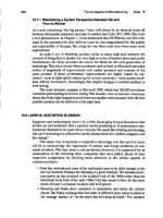
and then launching the product for sale. Figure 2.1 shows more details of these steps,
arranged in a clockwise order. Beginning at the top of Figure 2.1, some of the very first
survival questions that must be asked are:
• Who is the
customer?
Specifically, who is going to buy this product?
• How much will the product cost to manufacture? Specifically, what will be the
start-up, overhead, operating, and payroll costs associated with the product?
What will be the annual sales volume of the product? What will be the profit
margin?
• What level of
quality
is needed for the identified group of consumers?
• What is the deUvery time? Specifically, what is the time-to-market for the first
sales income of a new product? Will another company get to market quicker?
• How fast can the next product line be delivered to ensure flexibility?
• What are the management of technology issues that will ensure
long-term
growth
of the company? And is there a
barrier to entry
to hostile competition?
This chapter of the book contains six main sections that address these questions.
2'
MANUFACTURING
ANALYSIS: SOME
BASIC QUESTIONS FOR
A START-UP COMPANY
22
Manufacturing Analysis: Some Basic Questions for a Start-Up Company Chap. 2
Plastic-products
manufacturing
System
assembly
Conceptual
design
phase
Detailed
design
phase
Semiconductor
manufacturing
Figure 1:.1 Steps in the product development and fabrication cycle.The chart
moves clockwise from analyzing "Who is the customer'!" to business plans, to
design, 10 prototyping, to different types of fabrication, to sales.The content of
Chapter 2 and the order of the other chapters in the book are approximately
organized around this chart
2.2 ~UESTION 1, WHO IS THE CUSTOMER?
To establish the correct market niche for the product, an inevitable trade-off will
Occur between the four central factors of cost, quality, delivery, and flexibility
(CODF).
These issues are discussed in detail in this chapter, hut first, let's be a little
entertaining. Consider a spectrum of possible customers for the products that will be
made by <www.start-up-company.com>.
First, assume the customer is one of the U.S.national laboratories, and the new
company is going to make a device that will go into a nuclear weapon. In this case,
no matter how much it costs, or how long it takes to deliver, it has to be of the highest
integrity. No compromises on safety or reliability can be made. High costs and long
delivery times are likely.
Technical
invention
Who isthe
customer?
Potential new synergie!
\START»~
Next
product
Rapid protolyping
and design changes
Process planning
for manufacturing
and setup of machines
Computer ,
manufacturing
Metal-products
manufacturing
Market analysis
2.2 Question 1: Who Is the Customer?
23
Second, assume the customer is the aerospace industry, and your new company
will be one of many subcomponent suppliers. The emphasis on safety and reliability
will still be paramount, but some eye to cost will begin to be raised. Boeing knows
that the European Airbus is courting its customers and that Japanese manufacturing
companies are entering the commercial aircraft business.
Third, assume that the customer isa major automobile producer, and again, the
new company will be a subcomponent supplier. Reliability will still be of some con-
cern, in this era of 50,(){X)·milebumper-to-bumper warranties, but obviously cost
competitiveness will now be a bigger issue. Some compromise between quality (see
Section 2.3) and cost must occur.
Fourth, if the intended customer is Harrods of London or Nordstroms or
The Sharper Image, the consumer products that your company plans to supply
must be attractive and well priced but not as reliable as a nuclear weapon!
Finally, if the consumer product is destined for Krnart, high-volume, low-cost, and
adequate reliability are the market forces behind the design and manufacturing
decisions.
2.2.1 Market Adoption Graphs
A key challenge for a new company, especially in "high tech," is as follows:
•The engineering founders of the new company will almost certainly want to be
creative and build something new and exciting.
However, if the product and the company are going to be successful in the long run:
• The company must focus on who, or which group of consumers, will be the first
real market adopters. This provides and maintains the serious cash flow
needed to grow the company.
Measured over a long period of time, most products go through different stages
of research and development, initial acceptance in the marketplace, sustained
growth, maturity, and possible decline. The diagrams on the next two pages should be
interpreted in a qualitative rather than a quantitative way, but they are based on
trends that are seen in other publications on product development (Moore, 1995;
Poppel and Toole, 1995).
These articles usually trace just one product as follows: (1) the new product is
adopted slowly into the market at first; (2) if it is successful, a period of rapid growth
then occurs;
(3)
much later on in life, the market becomes well established and even
saturated; (4) finally,the market might fade as new products take over the role of the
original product.
For this book, several products have been placed along the graph in Figure 2.2.
This confuses the issue a little because all these products grow at different rates and
their gross incomes in the market are substantially different. But for product accept-
ance in general, as measured by a concept of market adoption, a graph that combines
many products is quite useful. (When speaking in public about the graph, the audi-
ence will usually "politely laugh" with the observation that buggy whips would be
way down in the bottom right corner of the graph and products related to Dolly the
24
Manufacturing Analysis: Some Basic Questions for a Start-Up Company Chap. 2
Ftpre2.2 The market adoption curve,
modified to include several products
cloned sheep would be way down in the bottom left corner.) Whether or not one of
these technologies will climb the market adoption curve depends on the following:
• The cost benefit to the consumer
• The robustness and usefulness of the technology to the consumer
• Complementary uses for the consumer (in the case of consumer electronics
this may well mean other applications or software that can run on the new
device)
• Whether or not the device falls in line with industry standards
Such projects bring out the difficulties associated with launching radically new
products. Geoffrey Moore (1995) introduced the phrase crossing the chasm to
emphasize this (Figure 2.3). In the early stages of a product's life, there will always
be some measure of a market. There is a small group of consumers who love tech-
nology enough to buy a new product, no matter how useful it is. perhaps just for
amusement or to be able to show off to their friends that they have the latest "cool"
thing on the market. But this early market of impressionable "technology nuts" or
"technophiles'' only lasts so long. The real growth of the product depends on the
first bullet above, namely, the cost benefit to the average consumer. This begs the
question, How can a product survive across this chasm between the early enthusi-
asts and the real market? Geoffrey Moore goes on to use a "head bowling pin"
analogy for capturing this phase of stable growth. As an example, he chooses the
now-familiar personal pager. Apparently, medical doctors were the first real market
adopters of the pager, and once the general public saw how useful they were, the
product "crossed the chasm" and accelerated rapidly up the S-shaped curve in
Figure 2.2.
'Autos
Steel
Personalcomputers
Telecommunications
and networking
(Mobile-wireless
technologies
Td"-}J'''StalC''
technologies •
2.2 Question 1: Who Is the Customer?
25
Flgure2.3 The
concept of "crossing the
chasm" (from Geoffrey Moore, 1995).
Purchasing by
compulsive
"technophiles"
Maturity tmontha)
2.2.2 Inevitable Trade-Offs between Cost, Quality, Delivery,
and Flexibility (CQDFI
This brief and informal introduction illustrates a wide spectrum of market opportu-
nities with a wide variety of quality levels and consumer choices.Thus, inevitably, any
company must face the rising costs (C) of adding higher quality
(Q),
faster delivery
(D),
or having a more flexible
(F)
manufacturing and supply line (Figure 2.4).
Despite the rising costs of quality, delivery, and flexibility,today's customers are
more informed and they expect more than they used to. For example, they expect a
Pentium chip to perform perfectly and yet be competitively priced. So how do man-
ufacturers respond to this? At first glance, manufacturing seems to require too many
trade-offs to simultaneously achieve high quality and fast delivery in small lot sizes,
while still maintaining low cost. For example:
• Supercomputers and high-end, graphics-oriented UNIX machines cannot be
fabricated quickly and in small lot sizes and then sold at CompUSA in a price
range suitable for families and college students.
• A Lamborghini Ora Ferrari cannot be fabricated quickly and in small lot sizes
and then sold at the price of a Honda Accord or a Ford Taurus.
However, on closer inspection, the marketplace does set up a compromise sit-
uation between the engineering constraints and the broader economic goals. This
compromise involves a reliable prediction of market size and type, supported by
design and fabrication systems that can appropriately address each market sector. In
this way, luxury automobiles will always be more expensive than economy cars, but
in the luxury car sector, the industry leaders will be those who refined their design
and manufacturing skills the best to give a high quality-to-cost ratio. Consumers are,
Purchasing by real
market adopters
I
26
Manufacturing Analysis: Some Basic Questions for a Start-Up Company Chap. 2
Figure2.4 Schematic graph of rising
costs for adding more quality to the
product, faster delivery (schematically
measured on the.r axis by the shortness
in days or weeks to deliver). and more
system flexibility (CQDF).Also compare
with Figure 2.10.
of course, highly influenced by cost, which must be clearly related to the benefits that
accrueThe relationship between cost and quality will thus be examined in the next
two main sections. The relationship between cost, delivery, and flexibility will follow.
2.3 QUESTION 2: HOW MUCH WILL THE PRODUCT COST TO
MANUFACTURE ICI?
2.3.1 General Overview to Calculating the Manufactured
Cost of a Product
Assume that N "" the number of devices sold over the life of a particular product.
The cost of each product is,in the simplest terms:
The cost of an individual product, C
=
(DIN + TIN) + (M + L + P) + 0 (2.1)
In this general equation the terms are:
• D
=
design and development costs. This includes conceptual design, detailed
design, and prototyping.
• T
=
tooling costs.This particularly includes costs for production dies.
These first two costs are amortized over the number of products made and
therefore divided by the number made, N. The next three costs are consumed by
every product, and finally there are the overhead costs.
• M
=
material costs per product.
• L
=
labor costs per product for operating machines, assembly, inspection, and
packaging.
• P
=
production costs per product associated with machine utilization,
including loan payments for machinery.
• 0
=
overhead costs. This might include rental space for offices and factory,
computer networking installation and servicing, phone installations and
Quality or
fast delivery
or Jlexibilny
Q,llD,F
2.3 Question 2: How Much Will the Product Cost to Manufacture
(e)?
27
Figure 2.5 Cosl breakdowns for manufacturing, similar to Equation 2.I-not to
S<;:1I1e(courtesyofOatwald,1988).
monthly costs, electrical and other physical services, general advertising, and
general support staff This cost is more of a flat rate for all activities and must
eventually be allocated per component. Reviewing this list of potential over-
heads, it is not surprising that many small companies build the first prototypes
in the garage or basement of one of the founders.
Another view of the above equation is shown in Figure 2.5 from Ostwald
(1988). It provides an overview-not to scale of all the costs involved in creating,
manufacturing, and selling a product. At the bottom of the chart, the prime costs are
for the direct labor and materials.
Manufacturing overhead
is then shown, which
accounts for the labor costs to run the overall factory, consumable materials such as
fixtures, and other charges for maintenance and the like. On top of this are many
other overhead type charges for running the organization. Included in the engi-
neering costs are the design and development costs for a particular product in Equa-
tion2.1.
Time-to-market is a phrase that will be used in this book to measure the time
between (a) the first moment an engineer starts to bill his or her time to the company
Profit
Selling
Contingencies
Enll;ineerinJl;
General and administrative
Manufacturing charges
Indirect materials
Indirect labor
Direct labor
Direct materials
Conversion
costs
Overhead
=.
'PrUne
cost.
COSI of goods
manufactured
'Cost of manufacturing,
development.and sales,
28 Manufacturing Analysis: Some Basic Questions for a Start-Up Company Chap. 2
at the "conceptual product" stage in Figure 2.1and (b) the moment the product is sold
to the first customer and some revenue occurs. Note in Figure 2.1 that the time-to-
market extends all the way around the diagram to the "9 o'clock position." Colloqui-
ally speaking, there are many opportunities to run up huge debts and "go broke"
before selling anything. Section 2.5 on delivery therefore examines the time-to-
market issue in more detail.
2.3.2 Specific Costs for Individual Manufacturing Processes
Given these introductory remarks, an interesting question now arises: Are some
manufacturing processes cheaper to use than others?
If so, since the designers and the production planners have a wide variety of
possible methods to choose from, why not choose one that gets the cheapest and
most predictable results?
The book now reviews the manufacturing processes of the "mechanical world"
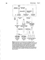
and discusses the constraints that arise. For a reader unfamiliar with mechanical
manufacturing processes, a brief taxonomy is given in Table 2.1. More details are
included in Chapters 4, 7, and 8.
The Manufacturing Advisory Service at <cybercut.berkeley.edu> shows illus-
trations and related information. The first entry is the solid freeform (SFF) family
that appeared after
19R7
with the introduction of SLA.The other families have been
categorized in that way by the Unit Manufacturing Process Research Committee of
the National Academy (Finnie, 1995).
The analysis that follows is based on personal experiences in the metal pro-
cessing industries and could probably be refined to suit other domains of manufac-
turing such as semiconductors. Also, the texts by Kalpakjian (1997) and Schey (1999)
cover similar material in their last fewchapters. Some of their diagrams and concepts
are integrated (with acknowledgment) into this text. Other work being expanded at
the time of writing isa "process selector" by Esawi and Ashby (1998).
2.3.3 Manufacturing Advisory Service (MAS) at
<cybercut.berkeley.edu>
Picture any of the standard mechanical components in a lawn mower, washing
machine, or even a simple can opener.
•Should the mechanical component be completely machined from a solid
block?
•Should it be near-net-shape cast or forged and then finish machined?
•Should it be welded or riveted together from several pieces of standard stock?
These are only three of many possible manufacturing routes. The route to
choose usually depends on a rather complex interaction between guiding eubpnncl-
pies of manufacturing process selection shown in Table 2.2.
2.3 Question 2: How Much Will the Product Cost to Manufacture
(e)?
2.
Family
TABLE2.1 A Brief Taxonomy
01
Mech8nlca/ Manuf&cturing
Proceue.
(Courte8y of
Flnn ••,l~)
BriefexplanalionofprocessesProcesses
LSolidrree.rorm
fabrk:atioo(SFF)
""""
alfeJlorlzed.
Iaye""
2 •••••.•••••••
p-
5. DeformaUon
I. Stereolithography
2. Selective laser
sintering(SLS)
3. Fused deposition
modeling (FDM)
1.Drilling
2.Milling
3.Thrning
4. Grinding
5. EDM and ECM
1.Casting
2. lnjection molding
of plasrics Icouki
includeFDM)
1.Coalings
2.SurfaceaUoying
3. Induced residual
1.Rolling
2. Sheet drawing
3. Extrusion
4. Forging
1.Powder metals
2.Cumposites
3.Weldinglbrazing
2.3.4 Batch Size
1.Stereoltthography (SLA) uses a laser to photocure liquid
polymers. 2.Selective laser sintering (SLS) uses a laser to
fuse powdered metal. 3.Fused deposition modeling
extrudes hot plastic through a nozzle. Like "mini-
toothpaste, hot extrusion," it builds up a model
These processes remove shapes from a solid block. called
the stock. LA simple drill from the hardware store creates
holes of different depth and diameter. 2.A milling cutter
has a flat end and can cut on its sides. It can carve out flat
pockets in a block to make an "ashtray." 3.Turning is done
on a lathe. The stock is round. The turning tool passes up
nnd down the rotating stock removing layers. "A round bar
can become a sculpted chair leg." 4. Grinding/polishing use
abrasives to remove thin layers of metal to greater accuracy
than processes 1 4.5. Electrodischarge machining uses
electric arc: Electrochemical machining uses charged
chemicals to remove fine layers.
I. In casting, mollen metal is poured into a hollow cavity in
sand, initially created from a mold. 2.lnjeclion molding
"shoots" hot liquefied plastic into a mold.
1.Hard surface coatings can be deposited chemically or
physically on softer or tougher substrates-c-chrome plating
is an example. 213.Alloying or shot blasting toughens
.ur{a"es.
1.Slabs can be rolled down to strip as thin as everyday
"aluminum kitchen foil." 2. Such sheets can be cut and ben!
into office furniture, filing cabinets, or soup cans. 3. Like
large-scale hot toothpaste, extrusions of different cross
sections can be made if the die (the hole at the end) is a
premade shape-using milling or EDM. 4. Hot or cold
forging involves "slamming" metal into a die cavity.The
metal stock plasticaUy deforms to the desired shape.
1.Powdered metal is formed in a die and then aintered to
give full strength. 2. Layers of different carbon fiber sheets
are an example of composite materials. 3.Welding involves
local melting and "mini casting together" of adjoining
plates. Brazing uses solid-state bonding between a filler
melalannth ••twnplales
When considering these subprinciples for a suggested manufacturing method, it
makes sense to begin with the criteria that make the most impact on the costs. Usu-
ally batch size,strength, geometry, and tolerance are the four most significant factors.
3.PbllIe-dumge
-
6,COlllOlklation
•
-
4. strumue-dumge
-
30 Manufacturing Analysis: Some Basic Questions for a Start-Up Company Chap. 2
General principles
driven by
designer
TABLE2.2 Subprlnclpl ••of Manufacturing Process Selaetfon
Implied considerations for Ihe manufacturing
process(mechllJljca1manufactqriogproce.~.es)
2. Batch sbe
3. Streagth lUld
welpt nlated
to material dtoke
4. Geometry
5. Tolertll;lccs
6. Product 6fe
7.LeadUme
8.Deslpror
usembly(DFA)
Cost is driven by all the principles below. It is reviewed in the tel(t in relation
toallpararneters.
Only the SFF, rapid-prototyping processes, machining, and possibly casting are
suitable for "just one" component. For a structurally useful product, only CNC
machining and casting are realistic, but FDM can provide an alternative for
low strength ABS-plaslic parts. For two to five components, CNC machining is
likely. As batch size increases, snort-run, plastic injection molding or casting is
considered. The cost of the die or mold is always a key factor
A need for high strength drives the choice toward metal processing over
plastic molding, Even higher strengths/performance will force the choice
toward forging or machining over casting. A need for light weight may drive
the choice to plastic, aluminum, or titanium. In general, costs will increase
when high strength and performance are required. Materials such as titanium
are very costly.
Wide, thin cruss ~eL"tions will drive choice toward blow molding for plastic parts
or sheet-metal forming for metal parts. "Chunky" cross sections drive the
choice to castinglforginglmilling operations."Cylindrical" cross sections drive
the choice to turning. In general, parts with complex geometries will cause high
manufacturing costs. In small batches, the CNC programming and execution
times will be long. 10 large batches, dies are expensive to create and operate.
Tolerances tighter than
+1-
50 microns (0.002 inch) will begin 10 drive the
choice to the machining/grinding/polishing family of processes. Grinding and
polishing are expensive operations-if possible the designer should avoid such
fmishingcosts.
A desired long service life will probably drive the choice to metal processing
over plastics. Design constraints on fatigue properties may require special
tooling and/or lapping processes. Longer desired service life will almost
certainly increase costs because of more or better materials used, improved
surface finish, and more careful design optimizetlona
To deliver the part to the designer quickly, production planners hope to use
standard processes and tooling. Weird designs might require special tools and
lengthy hand assembly and finishing. Special tools and fixtures will rapidly
drive up the costs and delivery time. Any process that requires a die or mold
will be more expensive and will take longer than machining or SFR
The way in which an individual part is mated or fixed to another one in an
assembly is also important. Welding, riveting, and bolting costs are high, and
these processes are often poorly controlled. Thus, cost reductions may result
from new assembly or single-piece manufacturing methods.
2.3.4.1 Batch Size of 1
If only one component is needed, then one of the rapid prototyping methods such as
stereolithography (SLA), selective laser sintering (SLS), fused deposition modeling
(FDM), CNC machining, or casting is the obvious manufacturing choice. The first
three listed are collectively known as solid freeform fabrication (SFF). Note that
SLA produces a low strength pbotopolymer model, not a structural part. SLS can
LC •••
2.3 Ouestion 2: How Much Willthe Product Cost to Manufacture
(e)?
31
create low strength metal parts, and FDM can create low strength ABS plastic parts.
The
Sff
and CNC machining processes are economic for
one-off
components
because they do not require the time to make an expensive die or mold prior to pro-
duction. Casting is also possible for large, complex single components that cannot
feasibly be made by machining. However, an expensive mold of wax or wood is
needed. This creates the shaped cavity in sand before the molten metal is poured in.
Actually, if the batch size is as low as only one or two components and if the
part geometry is simple, a skilled craftsperson might even use a manual milling
machine or lathe because the programming time for a CNC machine might not be
worthwhile. However, if the part geometry is complex,
it
is worth the time spent to
program the CNC machine even for one-off components. The reason for this is rea-
sonably subtle: on a manual machine, if an error is made near to the point when the
part is almost complete, "all is lost"
-c-not
only the piece of work material but all the
time that was invested up until that point. But on a programmable machine, if an
error is made toward the end, there may be a scrapped workpiece but all the geo-
metrical programming steps that were invested up until that point are stored in the
computer. This of course begs the question, How is part complexity measured? One
answer might be that part complexity increases with the number of lines of CNC
code needed to machine the part.
For a batch size of one, if the desired part has a complex geometry, SFF rather
than machining processes will be used. An object that resembles a doughnut will be
easy to make by the SFF methods but almost impossible to make by CNC machining
unless it can be made in two halves and joined along its equator. Speaking very gen-
erally, the more complex the shape, the more likely SFF processes will be used. How-
ever.component strength is a vital consideration. CNCmachining and casting are the
only viable alternatives if high strength is needed. Selective laser sintering (SLS) can
produce a metal part, but it will he weaker than one produced by machining. Fused
deposition modeling can produce a plastic part with reasonable strength-but, again,
one that is weaker than a part from plastic injection molding.
2.3.4.2 Batch Siz~
2
to 10
If only a few components, say 2 to 10,are needed, then CNC machining is today the
most likely choice, unless the geometry is highly complex and sculptured, in which
case a batch of SLS or FDM components might be realistic and cost effective.
2.3.4.3 Batch Size 10 to 500
A batch of 10 to 500 might well be done by CNC machining. This batch size is begin-
ning to enter the realm of a
productiun shop
rather than a
custom prototyping shop
(Figure 2.6). However, manual transfer of parts between machines willbe quite likely
since this batch size is not sufficient to warrant investments in automation.
It should also be noted that ifthe customer isincreasing its order from just one to
this higher batch size, it might be best to "backtrack" and make a good stereolithog-
'These numbers for batch size are very approximate and depend on several factors including part
complexity. The ranges in these next few pages deliberately overlap.
32
Manufacturing Analysis: Some Basic Questions for a Start-Up Company Chap. 2
flJure 2.6 Trends from manual, to CNC, to reprogrammable systems (FMS). and
10"harder automation" (courtesy of Ostwald,1988).
raphy pattern that willthen be used for castings.'Thisoption willwork ifthe desired tol-
erances are within the capability of both the SLA master and the subsequent casting
process, rather than machining.
2.3.4.4 Batch Size 100 to 1U,OOO
CNC machines, arranged in larger complexes called flexible manufacturing systems
(FMS), willbe favored as batch size grows. Perhaps robots Ofautomated guided vehi-
cles (AGVs) will be used to move parts from one machine to another. Efficiency will
be very dependent on the communication software needed to orchestrate the
system. However, batch sizes of several thousands will begin to warrant the Iabrica-
tion of an expensive die that can rapidly punch out products by a cold forging or
stamping process. While processes that require a premade die or mold are rarely, if
ever, used for one-off or short batch runs, the cost of the die can be amortized over
these larger funs and the
COSl
of the tooling die per component
decreases (parameter
T in Equation 2.1). Sands (1970) presents a comprehensive analysis for different
forming processes showing at which batch size the use of a die becomes efficient. Die
costs and manufacturing system costs increase from left to right in Figure 2.6.This
cost factor places an important responsibility on the designer. In an ideal situation
the newly designed component will be made on existing factory floor machinery,
readily leading to an "off-the-shelf" automation solution. In the best case, existing
fixtures and even some parts of existing dies will also be reused.
IJoblotindust~
Moderate
quantity
industries
Mi"ss production industries]
Mechanization
~grammable
, automatio~
Flexible work
station
csn
Work
station
Production
-systems
2.3 Question 2: How MuchWillthe Product Cost to Manufacture
(Cl?
33
2.3.4.5 Batch Size 5,000 to millions
As batch sizeincreases. automation plays a bigger role. However.for extremely large
batch sizes, it might even be economic to revert to noncomputerized machines.
Speaking colloquially, this batch size moves into the realm of "ketchup in bottles."
where fixed conveyor lines pump out the same product day in, day out. This is often
referred to as fixed or
hard automation,
literally because "hard stops" are fixed in
place with wrenches.These hard stops establish the positions where components rest
in place while being filled or labeled. Some basic computer control and sensors are
needed to keep things on track, but reprogramming will not be needed.
2.3.5
Material Choice
The material that the designer chooses for the part willbe influenced by weight con-
siderations, cost factors. and desired strength. This desired strength of the finished
object isobviously a key factor. Even though metals are generally stronger than plas-
tics. injection molded and thermoformed plastics are preferred for ordinary con-
sumer products such as household appliances, consumer electronics, and many
automotive products.
In general manufacturing costs for plastics are lower than those for comparable
metal products. This is because plastic forming requires much lower forces than
metal forming, and so the machinery is cheaper, the dies are less complex, and the
labor costs are often lower.However, critical components such as transmission gears
need to be made from closed die forging blanks to obtain a well-distributed grain
structure. Finish machining completes the critical gear tooth involute profiles. This
issue of basic strength is obviously related to the primary material that the object is
to be made from-not onlyits basic data-book strength but also its purity, heat treat-
ment, and in-process characteristics. The latter include the work-hardening proper-
ties of metals and the shrinkage characteristics of plastics.This is also an important
moment in the text to reemphasize that solid freeforrn (SFF')prctotyping techniques
such as stereolithography create plastic components from a photo-curable liquid.
This material from the SLA bath is by no means as structurally sound as standard
plastics such as ABS and polystyrene. FDM can create ABS parts of reasonable
strength, but not with the same structural integrity as injection molded ABS.
2.3.6
Part Geometry
The product's geometry embodies the aesthetic qualities and functional properties
of the part, but it also restricts the selection of suitable manufacturing processes.
Figure 2.7 is taken from Schey (1999) to show how one aspect of overall part geom-
etry drives process choice.To quickly understand this graph, begin by noting that the
cold rolling process nearest the
x
axis produces a flat strip that is at the extremes of
wide and thin. In fact the strips are often several feet wide and still only a few thou-
sandths of an inch thick. No other process can match rolling for such dimensions.
Cold rolling is thus one of the starting points for a large range of subsidiary processes
such as sheet forming and stamping, which then produce automobile body panels,
office furniture, and even the humble soup can.