Báo cáo nghiên cứu khoa học: "USING ADAPTIVE CONTROL TO SOLVE THE TRACKING PROBLEM FOR A MOBILE MANIPULATOR" pptx
Bạn đang xem bản rút gọn của tài liệu. Xem và tải ngay bản đầy đủ của tài liệu tại đây (846.71 KB, 11 trang )
TẠP CHÍ PHÁT TRIỂN KH&CN, TẬP 11, SỐ 03 - 2008
Trang 5
USING ADAPTIVE CONTROL TO SOLVE THE TRACKING PROBLEM
FOR A MOBILE MANIPULATOR
Tran Thien Phuc
University of Technology, VNU-HCM
(Manuscript Received on November 01
st
, 2007, Manuscript Revised March 03
rd
, 2008)
ABSTRACT: In this paper, the control of a mobile manipulator for tracking smooth 3D-
curved welding trajectory is discussed. This case can be found in any metal processing
factories such as ship building factories and pre-fabricated metal structure factories. The
mobile manipulator is made up of a multilink manipulator and a two-wheeled mobile platform.
The kinematic modeling and the constraints for both the platform and the manipulator are
discussed. Based on these modeling, an adaptive control algorithm for the welding mobile
manipulator is proposed. A candidate Lyapunov function is also introduced for proving the
stability of system upon the adaptive algorithm. For increasing the flexibility of system, the
control of system with unknown parameter such as the arc length of the torch is considered,
and an update control law based on the adaptive back-stepping method is proposed. In this
paper, the numerical simulation results are shown to illustrate the validity of the proposed
algorithm. The experiments are also performed for getting the good values of parameters and
proving the feasibility that a mobile manipulator is applied to a 3D smooth curve welding task.
Keywords: Mobile manipulator, 3D smooth curve welding task, unknown parameter,
update control law, adaptive back-stepping method.
1. INTRODUCTION
Recently, a mobile manipulator has been widely used in various industrial fields such as
ship building industry, automobile industry, electronic assembling, and pre-fabricated metal
structure industry. Furthermore, it can be applied to works in the hazardous environments such
as waste management and treatment, desolate exploration and even space operation.
Especially, the mobile robots are extensively used in industry for resistance and arc-welding
applications. The mobile manipulator can be used for performing the welding task with high
quality. Furthermore, the workers with the aid of the welding robot can perform their tasks
even in contaminative environment with smoke and light arc. Nowadays, the application of the
mobile robot to welding task has been studied by many researchers, such as Bui et al. (2003),
Fukao et al. (2000), Jeon et al. (2002), Lefeber et al. (2001), and Lee et al. (2001). These
mobile robots are focused on horizontal line tracking purpose. To attain the same purpose in
the narrow space, Yoo et al. (2001) used a mobile manipulator, a horizontal multi-link
manipulator mounted on a platform with two independent driving wheels. Thus, this mobile
manipulator was used only for the horizontal fillet welding paths.
In this paper, an adaptive controller is applied to a two-wheeled welding mobile
manipulator to track a smooth 3D-curved welding trajectory. To design a tracking controller,
the tracking errors are defined between the welding point on the torch and the reference point
moving at a specified constant welding speed along the welding trajectory. Both kinematic
modeling of the mobile platform and the manipulator are introduced. Hence, the relationship
between the input variables (angular velocities of the wheels of the platform and the links of
the manipulator) and the output parameter (position and velocity of the end effector) is
established. In order to increase the flexibility of the system, an adaptive control algorithm
Science & Technology Development, Vol 11, No.03- 2008
Trang 6
based on the back-stepping concept with unknown parameter such as the arc length of torch is
proposed. The simulations using MatLab V6.5 and Simulink V5.1 are also performed to show
the effectiveness of the proposed controller. The paper also shows how to get the tracking
errors by the potentiometer and the camera sensor. The experiments are performed for getting
the practical information. A camera sensor made in Carnegie Mellon University and a
potentiometer are used for gathering the feedback signals that are invoked for measure the
tracking errors.
2. SYSTEM MODELING
2.1. Configuration of the Mobile Manipulator
The following constraints will be examined for choosing the configuration of the mobile
manipulator. The orientation of the torch should lie on the tangent plane of the welding
trajectory at the welding point. The orientation of the torch should also be inclined with 45
degrees with respect to the intersectional line between the tangent plane and the welding
trajectory surface at welding point. This is considered for ensuring the good condition for the
quality of the welding seam.
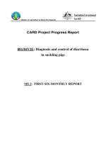
Fig 1. Mobile manipulator configuration Fig 2. Manipulator motion in welding process
According to the above conditions, in the configuration of the manipulator, the torch
orientation is fixed on the tilt of 45 degrees with respect to the link direction of the 4th-link.
The link direction of the 4th-link always is kept in the perpendicular direction of the welding
trajectory surface at the welding point (see in the Fig. 2 for more detail). With the above
condition, the torch orientation always lies on the plane which is created by the tangent line
and the normal line of the welding trajectory at the welding point, and is inclined with 45
degrees with respect to the tangent line of the welding trajectory at the welding point. The
rotation of the last link assures that the orientation of torch has a right gesture at the certain
1- Camera sensor
2- Welding torch
3- Link 2
4- Link 1
5- Link 0
6- Platform
7- Revolute joint
8- Revolute joint
9- Revolute joint
10- Revolute joint
11- Link 3+4
TẠP CHÍ PHÁT TRIỂN KH&CN, TẬP 11, SỐ 03 - 2008
Trang 7
welding point. In order to perform the welding task, an assignment for the mobile platform and
the manipulator is made as: the mobile platform should track the curved surface in which the
welding trajectory lies on, and the manipulator has the duty of reaching to the altitude of the
welding point.
2.2 Kinematic Modeling for the Mobile Platform
The kinematic equation of the platform can be described as the following:
⎥
⎦
⎤
⎢
⎣
⎡
ω
⎥
⎥
⎥
⎥
⎥
⎥
⎦
⎤
⎢
⎢
⎢
⎢
⎢
⎢
⎣
⎡
−
φ
φ
=
⎥
⎥
⎥
⎥
⎥
⎥
⎦
⎤
⎢
⎢
⎢
⎢
⎢
⎢
⎣
⎡
θ
θ
φ
φ
xy
C
C
l
r
C
C
C
v
rbr
rbr
y
x
//1
//1
10
0sin
0cos
&
&
&
&
&
, (1)
where
[]
T
lrCCCp
yxq θθφ=
is the generalized coordinate of the mobile
platform, for more detail,
)0,,(
CC
yxC
is the coordinate of the platform’s center point, and
C
φ
is the heading angle of the platform;
lr
θθ
&&
,
are the angular velocities of the right and left
wheels of the mobile platform;
br,
are radius of the wheel and the distance from wheel to the
symmetry axis, respectively ;
xy
v
and
φ
ω
are the straight and angular velocity of the
platform in x-y plane, respectively and are supposed be bounded values.
It is assumed that the wheels of the mobile platform do not slip. So, the velocity of C must
be kept in the direction of the axis of symmetry and the wheels must purely roll. The
constraints are expressed as follows:
0=
pp
q)A(q
&
, (2)
or for this case:
0
0sincos
0sincos
000cossin
=
⎥
⎥
⎥
⎥
⎥
⎥
⎦
⎤
⎢
⎢
⎢
⎢
⎢
⎢
⎣
⎡
θ
θ
φ
⎥
⎥
⎥
⎦
⎤
⎢
⎢
⎢
⎣
⎡
−−φφ
−φφ
φφ−
l
r
C
C
C
CC
CC
CC
y
x
rb
rb
&
&
&
&
&
. (3)
2.3 Kinematic Modeling for the Manipulator
In practice, the manipulator is considered as a plane mechanism with three links as shown
in Fig. 2. Furthermore, in welding process, to retain the correct direction of the torch with
respect to the welding path, the link 3 is always fixed in the horizontal direction. The
constraint can be expressed as below:
⎩
⎨
⎧
=ω+ω+ω
π=θ+θ+θ
0
321
321
. (4)
where
i
θ
and
i
ω
are the link variables and the angular velocities of the ith-link of the
manipulator.
The kinematic equation of the manipulator can be described as the following:
Science & Technology Development, Vol 11, No.03- 2008
Trang 8
mmE
q)J(qq
&&
=
, (5)
where
E
q
&
is position of the torch tip,
J
is Jacobian matrix of the manipulator,
m
q
is link
variable of the manipulator.
In case of the planar three-link manipulator, (5) can be re-expressed as:
⎥
⎥
⎥
⎦
⎤
⎢
⎢
⎢
⎣
⎡
θ
θ
θ
⎥
⎥
⎥
⎦
⎤
⎢
⎢
⎢
⎣
⎡
=
⎥
⎥
⎥
⎦
⎤
⎢
⎢
⎢
⎣
⎡
ω
3
2
1
333231
232221
131211
&
&
&
&
&
&
JJJ
JJJ
JJJ
z
x
E
E
E
, (6)
where
i
l
is the length of ith-link, and
)cos(),sin(
jiijjiij
CS
θ
+
θ
=
θ
+
θ
=
,
0,,
1332122313211
=
=+= JSlJSlSlJ
,
3232223112321
, CllJClCllJ +
=
+
+
=
,
1,
333231323
==== JJJlJ
,
The inverse kinematic equation is defined as:
⎥
⎥
⎥
⎦
⎤
⎢
⎢
⎢
⎣
⎡
ω
⎥
⎥
⎥
⎦
⎤
⎢
⎢
⎢
⎣
⎡
=
⎥
⎥
⎥
⎦
⎤
⎢
⎢
⎢
⎣
⎡
θ
θ
θ
=
⎥
⎥
⎥
⎦
⎤
⎢
⎢
⎢
⎣
⎡
ω
ω
ω
−−−
−−−
−−−
E
E
E
z
y
JJJ
JJJ
JJJ
&
&
&
&
&
&
1
33
1
32
1
31
1
23
1
22
1
21
1
13
1
12
1
11
3
2
1
3
2
1
, (7)
where
23132
1
1232
1
11
, SlSlJClJ −−==
−−
,
23132
1
21332
1
13
, ClClJSllJ −−==
−−
,
23132
1
22
SlSlJ +=
−
,
2331332
1
23
SllSllJ −−=
−
,
231
1
32231
1
31
, SlJClJ −==
−−
,
2312331
1
33
SllSllJ +=
−
.
2.4 Kinematic Equation for the Welding Torch Tip
The relationship between the welding point
),,,(
wwww
zyxW
φ
and the center of the
mobile platform
),,,(
CCCC
zyxC φ
can be expressed as following:
⎥
⎥
⎥
⎥
⎦
⎤
⎢
⎢
⎢
⎢
⎣
⎡
φ
θ+θ+θ+
φ+
φ−
=
⎥
⎥
⎥
⎥
⎦
⎤
⎢
⎢
⎢
⎢
⎣
⎡
φ
C
C
CmC
CmC
w
w
w
w
llz
py
px
z
y
x
)sin(sin
cos
sin
21211
(8)
where
m
p
is the distance from the projection of the manipulator torch tip on the x-y plane
to the center C of platform,
w
φ
is the heading angle in the horizontal plane of the welding
torch, and
C
φ
is the heading angle of the mobile platform.
Combining the derivative of (8) and the angular velocity of the torch yields the kinematic
equation for the welding torch tip as follows:
TẠP CHÍ PHÁT TRIỂN KH&CN, TẬP 11, SỐ 03 - 2008
Trang 9
⎥
⎥
⎥
⎥
⎥
⎥
⎦
⎤
⎢
⎢
⎢
⎢
⎢
⎢
⎣
⎡
ω
ω
ω
ω
⎥
⎥
⎥
⎥
⎥
⎥
⎦
⎤
⎢
⎢
⎢
⎢
⎢
⎢
⎣
⎡
θ+θθ+θ+θ
φ−φ
φ−φ
=
⎥
⎥
⎥
⎥
⎥
⎥
⎦
⎤
⎢
⎢
⎢
⎢
⎢
⎢
⎣
⎡
ψ
φ
ψ
φ
2
1
21221211
10000
00010
0)cos()cos(cos00
000sinsin
000coscos
xy
CmC
CmC
w
w
w
w
w
v
lll
p
p
z
y
x
&
&
&
&
&
(9)
where
w
ψ
and
ψ
ω
are the heading angle and the angular velocity of the welding torch in
vertical plane, respectively. It is assumed that
ψ
ω
is bounded.
3. CONTROLLER DESIGN
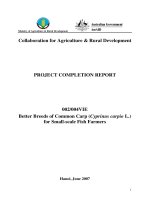
Fig 3. Tracking errors of the mobile manipulator
The vector
[]
T
eeeee
54321
is denoted as the vector of the tracking error that is the
difference between the welding position
),,,,(
wwwww
zyxW
ψ
φ
and the reference position
),,,,(
rrrrr
zyxR ψφ
(see Fig. 3 for more detail). This vector is expressed as:
Science & Technology Development, Vol 11, No.03- 2008
Trang 10
⎥
⎥
⎥
⎥
⎥
⎥
⎦
⎤
⎢
⎢
⎢
⎢
⎢
⎢
⎣
⎡
ψ−ψ
φ−φ
−
−
−
⎥
⎥
⎥
⎥
⎥
⎥
⎦
⎤
⎢
⎢
⎢
⎢
⎢
⎢
⎣
⎡
φφ−
φφ
=
⎥
⎥
⎥
⎥
⎥
⎥
⎦
⎤
⎢
⎢
⎢
⎢
⎢
⎢
⎣
⎡
wr
wr
wr
wr
wr
ww
ww
zz
yy
xx
e
e
e
e
e
10000
01000
00100
000cossin
000sincos
5
4
3
2
1
(10)
where the subscript r and w imply reference and welding, respectively.
A control law should be found out to obtain
0→
i
e
as
t →∞
for the welding point
W
to
become to coincide with its reference point
R
. Easily, the derivative form of the tracking
errors is as follows:
⎥
⎥
⎥
⎥
⎥
⎥
⎦
⎤
⎢
⎢
⎢
⎢
⎢
⎢
⎣
⎡
ω
ω
ψ
ψ
ψ
=
⎥
⎥
⎥
⎥
⎥
⎥
⎦
⎤
⎢
⎢
⎢
⎢
⎢
⎢
⎣
⎡
ψ
φ
r
r
rr
rr
rr
v
ev
ev
e
e
e
e
e
sin
sincos
coscos
4
4
5
4
3
2
1
&
&
&
&
&
⎥
⎥
⎥
⎥
⎥
⎦
⎤
⎢
⎢
⎢
⎢
⎢
⎣
⎡
⎥
⎥
⎥
⎥
⎥
⎥
⎦
⎤
⎢
⎢
⎢
⎢
⎢
⎢
⎣
⎡
−
−
−
−
+−
+
ψ
φ
ω
ω
z
xy
m
v
v
e
pe
1000
0010
0100
000
001
1
2
(11)
where
r
v
is the reference velocity in the welding trajectory, and is bounded and large than
zero,
x
y
v
is the x-y component velocity of
r
v
,
z
v
is the z component velocity of
r
v
,
rφ
ω
and
rψ
ω
are reference rotational velocity in x-y plane and vertical plane, respectively .
The projection of manipulator in x-y plane is denoted pm. In practice, the value of
parameter pm can be varied because the arc length of the torch depends on many other
parameters such as the current intensity of power supplied, and the geometric quality of the
surface. Thus, an adaptive controller is designed to obtain the control objective by using the
estimates of the parameter pm.
m
p
ˆ
and
m
p
~
are denoted as the estimated values and the
estimated error of
m
p
, respectively.
mmm
ppp
~
ˆ
+=
,
(12)
mm
pp
&
&
~
ˆ
=
, (13)
Equation (11) can be re-expressed as follows:
⎥
⎥
⎥
⎥
⎥
⎥
⎦
⎤
⎢
⎢
⎢
⎢
⎢
⎢
⎣
⎡
=
⎥
⎥
⎥
⎥
⎥
⎥
⎦
⎤
⎢
⎢
⎢
⎢
⎢
⎢
⎣
⎡
r
r
rr
rr
rr
v
ev
ev
e
e
e
e
e
ψ
φ
ω
ω
ψ
ψ
ψ
sin
sincos
coscos
4
4
5
4
3
2
1
&
&
&
&
&
⎥
⎥
⎥
⎥
⎥
⎦
⎤
⎢
⎢
⎢
⎢
⎢
⎣
⎡
ω
ω
⎥
⎥
⎥
⎥
⎥
⎥
⎦
⎤
⎢
⎢
⎢
⎢
⎢
⎢
⎣
⎡
−
−
−
−
+−
+
ψ
φ
z
xy
m
v
v
e
pe
1000
0010
0100
000
00
ˆ
1
1
2
(14)
The Lyapunov candidate function is chosen as follows:
2
4
2
3
2
2
2
1
cos1
2
1
2
1
2
1
k
e
eeeV
−
+++=
0
ˆ
2
1
2
1
2
6
2
5
>++
m
p
k
e
(15)
TẠP CHÍ PHÁT TRIỂN KH&CN, TẬP 11, SỐ 03 - 2008
Trang 11
The derivative form of (15) is expressed as follows:
m
m
p
k
p
eee
k
e
eeeeeeV
&
&&&&&
&
ˆ
ˆ
sin
6
554
2
4
332211
+++++=
)
ˆ
(
ˆ
)(
)cos(
sin
)sin()coscos(
6
15
22
2
4
341
k
p
epe
vek
k
e
vveveve
m
mr
rrrzrrxyrr
&
+ω+ω−ω+
ω−ω+ψ+−ψ+−ψ=
φψψ
φφ
The control law is chosen as the following:
⎪
⎪
⎪
⎩
⎪
⎪
⎪
⎨
⎧
ω−=
+ω=ω
+ψ+ω=ω
+ψ=
+ψ=
φ
ψψ
φφ
16
55
4422
33
114
ˆ
sincos
sin
coscos
ekp
ek
ekvek
ekvv
ekevv
m
r
rrr
rrz
rrxy
&
(16)
where
654321
,,,,, kkkkkk
are positive values.
From (15) and (16),
V
&
can be re-expressed as the following:
0sin
2
554
2
2
4
2
33
2
11
≤−−−−= eke
k
k
ekekV
&
(17)
It is assumed that all errors ei are bounded so
V
&&
is bounded too, that is to say,
V
&
is
uniformly continuous. Since
V
does not increase and converges to certain constant value, by
Barbalat's lemma,
0→V
&
as
∞
→
t
(Fierro and Lewis (1995)). When
V
&
equals zero, from
(17) one can implies that
[]
0
5431
→
T
eeee
as
∞
→
t
. From the third row of (16) it is
easy to obtain
0
2
→e
as
∞→
t
.
And so, from (1), (7), and (16), the control law for mobile manipulator with update rule
can be expressed as the following:
⎥
⎥
⎥
⎥
⎦
⎤
⎢
⎢
⎢
⎢
⎣
⎡
ω
ω
⎥
⎥
⎥
⎥
⎥
⎥
⎥
⎥
⎥
⎦
⎤
⎢
⎢
⎢
⎢
⎢
⎢
⎢
⎢
⎢
⎣
⎡
−
θ
θ−θ−
θ
θ
−
=
⎥
⎥
⎥
⎥
⎥
⎥
⎥
⎥
⎦
⎤
⎢
⎢
⎢
⎢
⎢
⎢
⎢
⎢
⎣
⎡
ω
ω
ω
ω
ω
ψ
φ
ψ
z
xy
m
l
r
v
v
ek
l
l
rbr
rbr
p
000
1000
00
sin
sinsin
0
00
sin
sin
0
0/0/1
0/0/1
ˆ
16
2
121
2
12
2
1
&
(18)
and
)(
213
ω
ω
ω
+−=
Science & Technology Development, Vol 11, No.03- 2008
Trang 12
4. SIMULATION AND EXPERIMENT RESULTS
Table 1. Numerical values for the simulation
Parameter K
1
k
2
K
3
K
4
k
5
p
m
l B r
Value 1 5 1.5 2.5 1.2 380 222 150 30
A reference welding trajectory as shown in the Fig. 6 is chosen for simulation and
experiment. Matlab software (version 6.5) and Simulink software (version 5.1) are also
invoked to perform the simulation. Some parameter values of the mobile manipulator used in
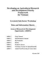
the simulation are given in Table 1. In Figs. 4 and 5, the model of mobile manipulator used in
the experiments is shown. The simulation results are shown in the Figs. 7 - 10.
Fig 4. Implementation of the control system Fig 5. Mobile manipulator in welding process
In Figs. 7 and 8, all of tracking errors converge to zero after about 4.5 seconds, and they
show the validity of the proposed algorithm. Fig. 9 shows the estimation value
m
p
ˆ
, and the
comparison between reference and welding trajectories is shown in Fig. 10.
The experiments are also performed, and the results are shown in Figs. 11 - 15. For an
easy comparison, both the simulation value and the experiment value of the same tracking
error are put on the same graph.
The experiment results with the errors not exceed 1mm or 1.5 degree from the simulation
values show the feasibility of proposed algorithm for applied on welding process after the
system is stable.
TẠP CHÍ PHÁT TRIỂN KH&CN, TẬP 11, SỐ 03 - 2008
Trang 13
Fig 6. Reference 3D curved trajectory Fig 7. Tracking errors e1, e2, e3
Fig 8. Tracking errors e4, e5 Fig 9. Estimate value of pm
Fig 10. Reference and welding trajectories Fig 11. Tracking error e1
Science & Technology Development, Vol 11, No.03- 2008
Trang 14
Fig 12. Tracking error e2 Fig 13. Tracking error e3
Fig14. Tracking error e4 Fig 15. Tracking error e5
5. CONCLUSIONS
The proposed algorithm is really simple and very easy for use but it has shown the
feasibility of an application performing a smooth 3D curved welding trajectory. The controller
of the mobile manipulator is designed based on the Lyapunov stability and the kinematic
modeling. The algorithm also solves a common problem that occurs in welding process: the
arc length cannot be precisely measured. An unknown parameter adaptive control update law
was used for solving this problem. The simulation results show the quick convergence to zero
of the tracking errors and the good system response of model in the welding process. The
experiment results also show the validity of the proposed control algorithm.
TẠP CHÍ PHÁT TRIỂN KH&CN, TẬP 11, SỐ 03 - 2008
Trang 15
ÁP DỤNG ĐIỀU KHIỂN THÍCH NGHI VÀO BÀI TOÁN THEO VẾT ĐƯỜNG
HÀN CHO TAY MÁY DI ĐỘNG
Trần Thiên Phúc
Trường Đại học Bách khoa, ĐHQG-HCM
TÓM TẮT: Chủ đề của bài báo này là điều khiển một tay máy di động theo vết một
đường cong hàn không gian. Đây là vấn đề thường gặp trong các nhà máy gia công kim loại
cỡ lớn như đóng tàu hay kết cấu thép tiền chế. Tay máy di động ở đây bao gồm một tay máy
nhiều bậc tự do và một xe robot dạng hai bánh. Bài báo trình bày các vấn đề về mô hình động
học của c
ả hai phần tử này. Bộ điều khiển thích nghi cho tay máy di động được xây dựng dựa
trên mô hình này. Tiêu chuẩn ổn định Lyapunov được sử dụng để chứng minh sự hội tụ ổn
định của sai số hệ thống. Nhằm tăng tính thực dụng của hệ thống, thông số dự đoán là chiều
dài hồ quang hàn được tính đến trong bài toán. Các thí nghiệm mô phỏng và thực nghiệm trên
mô hình cũng được tiến hành
để chứng minh tính khả thi của bộ điều khiển.
REFERENCES
[1]. Bui, T. H., Nguyen, T. T., Chung, T. L. and Kim, S. B., A Simple Nonlinear Control
of a Two-Wheeled Welding Mobile Robot, International Journal of Control,
Automation, and Systems (IJCAS), Vol.1, No.1, March, pp.35-42, (2003).
[2]. Fukao, T., Nakagawa, H. and Adachi, N., Adaptive Tracking ontrol of a
Nonholonomic Mobile Robot, IEEE Transaction on Robotics and Automation, Vol.
16, No.5, pp. 609-615, (2000).
[3]. Jeon, Y. B., Kam, B. O., Park, S. S. and Kim, S. B., Modeling and Motion Control of
Mobile Robot for Lattice Type Welding, International Journal (KSME), Vol. 16, No
1, pp.83-93, (2002).
[4]. Lee, T. C., Song, K. T., Lee, C. H. and Teng, C. C, Tracking Control of Mobile
Robots Using Saturation Feedback Controller, IEEE Transaction on Control Systems
Technology, Vol. 9, No. 2, pp. 305-318, (2001).
[5]. Lefeber, E., Jakubiak, J., Tchon, K. and Nijmeijer, H., Observer Based Kinematic
Tracking Controllers for a Unicycle-type Mobile Robot, in Proceedings of the 2001
IEEE Intl. Conference on Robotics and Automation, Vol. 2, pp. 2084-2089, (2001).
[6]. Lewis, F. L., Abdallah, C. T. and Dawson, D. M., Control of Robot Manipulators,
Macmillan Publishing Company, 866 Third Avenue, New York 10022, (1993).
[7]. Yoo, W. S., Kim, J. D. and Na, S. J., A Study on A Mobile Platform-Manipulator
Welding System for Horizontal Fillet Joints, Pergamon, Vol 11, pp. 853-868, (2001).
[8]. Fierro, R. and Lewis, F. L., Control of a Nonholonomic Mobile Robot: Backstepping
Kinematics into Dynamics, in Proceedings of the 1995 IEEE Intl. Conference on
Decision and Control, Vol 11, pp. 3805-3810, (1995).