Báo cáo nghiên cứu khoa học: "THE IMPLEMETATION OF GFP CORE ON FPGA HARDWARES" pdf
Bạn đang xem bản rút gọn của tài liệu. Xem và tải ngay bản đầy đủ của tài liệu tại đây (941.28 KB, 10 trang )
TẠP CHÍ PHÁT TRIỂN KH&CN, TẬP 9, SỐ12 -2006
Trang 13
THE IMPLEMETATION OF GFP CORE ON FPGA HARDWARES
Thuong Le Tien
(1)
, Viet Dinh Thanh
(2)
(1) University of Technology, VNU-HCM
(2) Munich University of Technology, Germany
(Manuscript Received on April 1
st
, 2006, Manuscript Revised November 2
nd
, 2006)
ABSTRACT: In order to take advantage of the widely-deployed existing SDH network
for transporting the traffic of multi-media applications such as voice, data and video, ITU-T
have standardized new technologies including GFP (Generic Framing Procedure), LCAS (Link
Capacity Adjustment Scheme) and RPR (Resilient Packet Ring), which will be implemented on
this network. GFP is the basis for mapping different types of traffic such as Ethernet, SAN -
Storage Area Network (ESCON, FICON, Fiber Channel), DVB ASI, etc into SDH virtual
containers. In the scope of the paper, we study the mentioned technologies, especially ITU-T
G.7041 standard for GFP which specifies types of header, error correction algorithms, frame
delineation algorithm for mapping and unmapping GFP frames. Based on this standard, we
have used VHDL to figure out a complete GFP core with MAP and UNMAP sub-cores. The
core is tested on Xilinx ModelSim5.6. Then these VHDL modules are compiled by ISE 6.3 3i to
be implemented on FPGA hardwares of Xilinx Company.
Keywords: NGN, GFP-F, GFP-T, LCAS, RPR, ESCON, FICON, Ethernet, Frame, FPGA,
SDH, NG SDH, VC
1. INTRODUCTION
To meet higher and higher demands of communications, carrier telecom networks must be
upgraded into NGN (Next Generation Network) [1,3,6]. NGN is a layered and converged
network with open and standardized interfaces between each layer, which supports different
multi-media applications. For transport layer, most of networks use traditional SDH
(Synchronous Digital Hierarchy) equipment, which was designed to carry voice traffic, and as
such is an inherently rigid and inefficient method for transporting data, such as Ethernet.
Therefore, traditional SDH systems should be replaced by Next Generation SDH (NG SDH) to
be deployed as transport layer in NGN [1,2,3]. ITU-T have standardized new technologies to be
implemented on NG SDH including GFP, LCAS and RPR. While RPR makes SDH ring to be
able to transport point-to-multipoint data, flexibly utilize and secure the ring bandwidth, GFP
and LCAS make SDH more flexible and efficient for carrying different types of traffic
[1,2,3,6]. GFP is developed to map different traffic types such as Ethernet, SAN (ESCON –
Enterprise Systems Connection, FICON – Fiber Connection, Fiber Channel), DVB ASI, etc
into SDH virtual container (VC) [4]. GFP helps SDH equipment groom many channels into a
VC or many VC with each other to serve one interface as well as allows bandwidth to be
specified in increment of 1 Mbit/s (10/100/1000BaseT). LCAS defines an automatic set-up and
tear-down of virtually concatenated groups VC`s, and allows dynamic bandwidth provisioning
without traffic interruption [2,3].
GFP, with framing structure specified by ITU-T G.7041, can be programmed by VHDL to
be implemented as a complete GFP core on FPGA hardware [4,7,8,9,10]. Successful generation
of GFP core on popular FPGA hardwares contributes a lot to the process of upgrading
traditional SDH into NG SDH.
At the moment, world-leading telecom suppliers such as Siemens, Alcatel, Nortel, Fujitsu,
etc commercialize NG SDH equipment. However, they are brand-new complete systems. We
have to replace completely existing equipment by new systems to upgrade existing network to
NG SDH. It’s really wasteful and costly. Therefore, our approach is to generate a complete
Science & Technology Development, Vol 9, No.12 - 2006
Trang 14
GFP core on FPGA hardwares and then combine these cores with existing SDH equipment to
carry different traffic types. Some well-known FPGA manufacturers such as Xilinx, Xelic,
Paxonet, have made efforts in doing research and developing this core. In scope of this paper,
we study mentioned new technologies, especially GFP. Then, we work out this core in VHDL
with frame structure, header, payload, error correction algorithms and delineation algorithms
according to G.7041. GFP core includes a MAP sub-core for mapping Ethernet frames into
GFP frames and an UNMAP for vice-versa process.
This paper includes 3 parts. Part 1 mentions the new technologies on NG SDH, especially
GFP in details according to G.7041 [4]. Functional blocks and models for implementing GFP
core are presented in Part 2. Part 3 illustrates core tests on ModelSim, summarizes the results
and expects the topic development in the future.
2. GFP TECHNOLOGY IN NEXT GENERATION SDH
2.1
Drawbacks of traditional SDH – Trend of Next Generation SDH
Traditional SDH have limitations in transporting high-bandwidth and burst applications as
it was intentionally designed to carry E1, i.e serve pure voice [1,2]. It cannot provide flexible
bandwidth such as 1Mbs, 2Mbs, …, 10Mbs, 15Mbs but fixed rate of vitual container such as
VC-12 (2Mbs), VC-3 (34/45 Mbs), VC-4 (155 Mbs). This is wasteful and unefficient. In some
cases, though user has the demand of 50Mbs interface for video application, he has to pay for
155 Mbs, i.e 90Mbs is empty and useless. This leads to the requirements for new transport
systems [1,3]:
•
Cost saving.
•
Leverage installed SDH infrastructure.
•
Operational efficiency and flexibility: utilize the capacity of available fiber to
flexibly provision bandwidth for different applications, allocate bandwith
dynamically and to be centrally managed.
•
Carry different applications with committed CoS and QoS.
•
Balance voice and data traffic.
•
New technologies for traffic engineering
From above requirements, NG SDH with new technologies has been developed to function
as transport layer in NGN.
2.2 New technologies in NG SDH
2.2.1.GFP technology
GFP is an open standard (ITU G.7041) for efficiently mapping packet-based services to
circuit based traffic [4]. Client signals may be PDU – protocol data unit - oriented (such as
IP/PPP or Ethernet MAC), or block-code oriented constant bit rate stream (such as Fiber
Channel or ESCON/FICON). Actually, there are old technologies to do this mapping; however,
it’s not really efficient. Currently, two modes of client signal adaptation are defined for GFP:
•
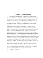
GFP–F (Framed): Designed for carrying packet traffic with varying frame length, e.g.
Ethernet traffic. A single client data frame (e.g. Ethernet frame) is mapped into a single GFP
frame; thus keeping the payload length variable. In order to determine the client frame length,
the complete client has to be mapped into a GFP frame as in
Fig (1). Sub-channel multiplexing
within the GFP channel allows multiple data streams to be assigned within the SDH containers
with fine granularity.
•
GFP-T (Transparent): A transparent channel for any protocol, providing the packet-
based equivalent of a traditional leased line. A fixed number of client characters are mapped
into a GFP frame of predefined length, thus keeping the payload length static. GFP–T provides
TẠP CHÍ PHÁT TRIỂN KH&CN, TẬP 9, SỐ12 -2006
Trang 15
a single transparent traffic stream and is intended for fixed-rate packet traffic (e.g. Fibre
Channel or FICON traffic used by storage area networks). Compared to the GFP-F framing,
GFP-T framing shows a reduced latency which is critical for SAN applications.
Figure 1. Example of GFP-F framing procedure for Ethernet over SDH
2.2.2.GFP compared to existing Packet-over-SDH technologies
Table 1. GFP compared to other existing technologies
Ethernet over ATM Ethernet over LAPS Ethernet over GFP
- Support fixed payload
length (Segmentation and
Reassembly needed for
payloads larger than 48
bytes)
-
Deterministic overhead
-
Supports variable payload
length.
-
Non-deterministic overhead.
-
Byte-stuffing may result in upto
50% overhead, and interferes
with QoS management
-
Supports variable
payload length
-
Deterministic
overhead.
GFP-F offers increased flexibility and bandwidth efficiency compared to existing Packet-
over-SDH technologies such as LAPS (Link Access Procedure – SDH, according to ITU-T
X.86) and ATM (Asynchronous Transfer Mode) when mapping Ethernet over SDH [1,3,4].
GFP-F does not rely on flag characters, and associated control escape octet, for frame
delienation purposes as HDLC (high layer data link control) does. Instead, GFP-F uses a
variation of the HEC-based (Header Error Control) frame delineation mechanism defined for
ATM. This avoids non-deterministic expansion of the client signal due to insertion of control
escape characters. An overview of the comparison of three technologies are shown in Table 1.
One of the most prominent GFP’s characteristics is sub-channeling. With this, many
channels such as FE, GE,…are grouped into one STM-N. Sub-channeling makes SDH more
flexible and efficient for carrying data traffic.
Science & Technology Development, Vol 9, No.12 - 2006
Trang 16
2.2.3.Other new technologies in NG SDH
Together with GFP, LCAS, RPR and MPLS (Multi Protocol Label Switching) are new
technologies to be implemented on NG SDH [1,2,3]. LCAS is defined according to ITU-T
G.7042. By using LCAS, the capacity of the GFP channels can be dynamically altered at any
time without traffic interruption by exchanging signaling information through some of reserved
fields in the virtual concatenation overhead bytes.
RPR
Protection
by RPR
Primary
label
switched
path
Backup label
switched path
MPLS
RPR
Metro
Access
Metro
Core
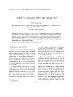
Figure 2. New technologies are combined in Metro Network
RPR is an emerging technology currently being standardized within the 802.17 Working
Group of the IEEE [5]. An RPR is a ring-based architecture that consists of packet-switching
nodes connecting to adjacent nodes over a single fiber pair which can be built on top of an SDH
ring. Implementing RPR in an SDH combines the low cost and simplicity of packet based,
connectionless networking with the reliability, bandwidth and scalability of SDH networks.
RPR, together with GFP, makes SDH enriched with data features with point-to-point and point-
to-multipoint transporting.
MPLS provides capabilities similar to RPR, but for a mesh topology [1]. The technique was
developed as a packet-based technology and is becoming widely adopted in optical networks
including converged data and voice networks. MPLS identifies traffic patterns and sets up a
path based on traffic demands. Routing is accelerated because the packet knows its path in
advance, rather than having to stop and be interrogated at every hop in the network.
Fig. 2
illustrates the combination of new technologies in a NG SDH network.
3. GFP CORE IMPLEMENTATION
3.1.GFP according to ITU-T G.7041
Two kinds of GFP frames are defined: GFP client frames and GFP control frames [4]. GFP
also supports a flexible (payload) header extension mechanism to facilitate the adaptation of
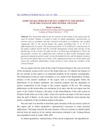
GFP for use with diverse transport mechanisms. The format for GFP frames is shown in
Fig. 3.
GFP frames are octet-aligned and consist of a GFP Core Header and, except for GFP Idle
frames, a GFP Payload Area. Frame structure with specified fields and number of bits/bytes,
header generation algorithms, FCS generation algorithms as well as frame delineation
algorithms are indicated in the standard.
TẠP CHÍ PHÁT TRIỂN KH&CN, TẬP 9, SỐ12 -2006
Trang 17
1 2 3 4 5 6 7 8
Transmission order
4 - 65535
4
Core Header
Payload area
1
2
3
4
5
.
.
.n
Core Header
Payload area
16-bit payload
legnth indicator
cHEC
(CRC – 16)
Payload headers
(4 – 64 bytes)
Optional payload
FCS (CRC – 32)
Client payload
information field
Transmission order
Figure 3. Frame format for GFP client frames
3.2.Model of core design and simulation
GFP CORE
MAP
CORE
UNMAP
CORE
Loopback
Module
MAP Line IF
UNMAP Line IF
Figure 4. Block diagram of core design
Fig. 4 shows the core design with 03 blocks: MAP core, UNMAP core and Loopback
module. In system applications, loopback module is used to isolate GFP core from data stream.
For this case, loopback module connects MAP and UNMAP line interfaces together enabling
MAP core to transfer data to UNMAP core.
UNMAP System
IF
MAP Host IF
MAP System IF
MAP Line IF
UNMAP
Line IF
GFP CORE
MAP
CORE
UNMAP
CORE
Loopback
Module
Testbench
Data Driver
Procedures
Clk/
Reset
Hình 5. Simulation block diagram
Science & Technology Development, Vol 9, No.12 - 2006
Trang 18
For simulation in Fig. 5, testbench module initiates MAP core and UNMAP core, loopback
module and other files. Testbech generates data, input them into MAP system interfaces as well
as get output data from UNMAP systems.
Funtions of modules in
Fig. 5 are as follows:
•
Clock generation: This module creates all clocks required for demonstration testbench.
By default, all clocks are connected to M_CLK interface.
•
Gfp_procedure: This module contains all functions and procedures used to create the
bus functional model of the MAP core’s system interface.
•
Gfp_testcase_pkg: This file contains all global variables and constants.
•
Gfp_driver: This module is used to pass data to/from the GFP core by transmitting data
to the MAP core’s system interface. Data is transferred from the data driver to the MAP core
using procedure calls. These procedures support transport of valid and invalid frames, which
enable us to observe both normal operation and the core response under various error
conditions.
•
MAP CORE: Mapping traffic types into GFP frames.
•
UNMAP CORE: It gets the original frames from GFP frames.
3.2.1.MAP core operation
MAP core do the following funtions:
•
Scrambling header with Barker series.
•
Insert error control for core, type and extension header (cHEC, tHEC and eHEC).
•
Scrambling payload with generating polynomial x
43
+1.
•
FCS Generation.
•
Management frames and idle frames transmission.
Fig 6. Waveforms of signals after running simulation of the core on ModelSim
TẠP CHÍ PHÁT TRIỂN KH&CN, TẬP 9, SỐ12 -2006
Trang 19
Fig (6) simulates basic operation of frame transmission at system interfaces of MAP core.
Sample data with 32 bit width (Hex) are transmitted incrementally as follows: 00000000,
00000001, 00000002, … 00000007 (1
st
frame), 00000008, 00000009, … 0000000F(2
nd
frame),… Frame transmission is initiated by asserting m_sys_src_rdy_n to inform that source is
ready. Then m_sys_sof_n is set to notice the start of frame and̀ m_sys_eof_n is set at the end of
frame. It is possible that both signals could assert at the same time, if the GFP frame contains
one or fewer words of data, or if it is a management frame.
All valid frame cycles (including the cycle beginning with m_sys_sof_n and ending with
m_sys_eof_n) must be qualified by the assertion of both m_sys_src_rdy_n and
m_sys_dst_rdy_n. If either of those signals are deasserted, the cycle is considered invalid. The
number of frame transmission cycles depends on the length of frame, which is indicated in
m_sys_length. For this simulation model, frame length is 31 bytes with value of m_sys_length
001F. When end of frame, m_sys_eof_n is set with the last data word. M_sys_rem is used to
indicate how many bytes of the last data word are valid. Here m_sys_rem is 11 for normal
word, i.e data [31:0] valid, and 10 for the last word, i.e data [31:8] valid.
Due to the nature of packet and frame based protocols, GFP MAP core and UNMAP core
have been pipelined to maximize the performance. Data is delivered to MAP core takes several
clock cycles before the completed frame appears at the line interface due to the pipelining
required to insert the header fields and create FCS and HEC fields. We can see this on
Fig. 7.
At first clock cycles, when there are no input data on system interfaces of MAP core, data on
m_line_data and u_line_data are B6AB31E0. This is Barker series with the length of 32, which
is used to scramble core header. As scrambling of header is done by XOR operation of Barker
series and data, at first clock cycles, data on receiving side should be B6AB31E0. Data on
receiver is always about 20 clock cycles later than input data. After reset, at 17
th
clock cycle,
data is inputted into core. However, at 37
th
cycle, GFP frame occurs at line-interfaces of MAP
core.
Fig 7. Data from Sys interfaces (m_sys_data) are encapsulated into GFP frames via MAP core and
transferred to line interfaces (m_line_data).
If GFP frame have extension field, CID must be showed on M_SYS_CID. This signal
should be present during frame transmission, from SOF to EOF.
When user determines there is an error condition with the frame data, the frame may be
discontinued with an immediate assertion of M_SYS_DSC_N and M_SYS_EOF_N.
M_SYS_SOF_N and M_SYS_EOF_N must still demarcate the frame data, but the MAP core
Science & Technology Development, Vol 9, No.12 - 2006
Trang 20
will now regard the entire frame as corrupt, the MAP core will pad the current frame with 1s
until the proper length (indicated in m_sys_length) is reached. If the number of bytes indicated
in length is different from actually received bytes, m_sys_status_n will be 0. MAP core
responds to errored data frame in the following ways:
•
Missing SOF: If a new frame is started (immediately after reset, or following an EOF)
without an SOF, the data will be ignored and discarded until a SOF initiates a new frame.
•
Early, late or missing EOF: If an EOF is received too early, the core will pad the frame
with 1’s until the correct length is reached, invert the FCS and assert M_SYS_DSC_N. If EOF
is received too late or is missing, the core will ignore all data words after correct length is
reached, invert FCS and assert M_SYS_DSC_N.
•
CID change in the middle of frame: If M_SYS_CID is changed in the middle of frame,
MAP core will pad the current frame with 1’s until the proper length is reached, and insert EOF
and DSC.
Management frame: When M_SYS_MGNT_N is asserted, no data will be on
M_SYS_DATA and M_SYS_REṂ. M_SYS_UPI determine the type of management frame to
be sent. Insertion of sys_mgnt_n into the mid of data frames will cause the interruption of them
and then management frames start to be transmitted.
3.2.2 UNMAP core operation
Fig. 8 illustrates the operation of interfaces of UNMAP core. UNMAP core receives GFP
frames from line interfaces of MAP core and do unmapping process to get the original data.
UNMAP core strips all GFP headers and FCS out of GFP frames. If there are errors in payload,
header or FCS, error signals will be active.
Fig 8. Signals on UNMAP core
Generally, all system interfaces of UNMAP core funtions as the same as relevant interfaces
of MAP core but opposite direction. Please be noted that U_SYS_STATUS_N[15:0] is used to
inform the delineation frame status with the following values:
•
[15:5] and [3]: reserved
•
[4]: FIFO almost full
•
[2]: “SYNC” status
•
[1]: “PRESYNC”status
•
[0]: “HUNT”status.
TẠP CHÍ PHÁT TRIỂN KH&CN, TẬP 9, SỐ12 -2006
Trang 21
4. CONCLUSION
GFP core is successfully generated with the following prominent features:
•
32 bit data.
•
Scrambling core header with Barker series and scramble payload with generating
polynomial x
43
+1.
•
Functional block of generating FCS and inserting FCS into GFP frame.
•
Detecting and corresponding well to errors such as (missing, early or late) End of Frame
và Start of Frame.
•
Support one bit error correction and multiple bit detection for header and payload.
•
Frame delineation for transmitter and receiver well done according to G.7041 standard.
In conclusion, core is designed with full requested features for mapping Ethernet frames
into GFP frames according to G.7041. Successfully programming complete GFP core in VHDL
to be implemented on FPGA hardware, which can be used in real network, is a good reference
for other applications on FPGA. With these cores, we can upgrade or add some new features
into network systems, not only for transport layer but also for other layers with the most
flexibility and cost savings as well.
THỰC HIỆN CORE CHO KHUNG GFP TRÊN PHẦN CỨNG FPGA
Lê Tiến Thường
(1)
, Đinh Thành Việt
(2)
(1) Trường Đại học Bách khoa, ĐHQG-HCM
(2)
Trường Đại học Công nghệ Munich, CHLB Đức
TÓM TẮT: Bài viết trình bày về việc thiết lập một chuẩn ITU-T G.7041 cho giao thức
khung GFP trong mạng SDH (Synchronous Digital Hierarchy), thực hiện các header, thuật
toán sửa lỗi và các khung ánh xạ và không ánh xạ GFP. Tác giả cũng đưa vào ngôn ngữ đặc
tả phần cứng VHDL để thực hiện một core GFP với các lõi core phụ MAP và UNMAP. Phần
thiết kế bằng ngôn ngữ VHDL sau đó dược mô phỏng trên Xilinx ModelSim 5.6 và ISE 6.3 3i và
từ đó có thể triển khai ứng dụng vào phần cứng FPGAs của hãng Xilinx.
REFERENCES
[1]. Dr. Stefan VollGerlinde Bedu, Multi-Service Integration in Next Generation Network,
Siemens Training Institute, (2004).
[2].
B. Hilderbrandt, Multi-service Metro Networks Application, Siemens AG, ICN CN
SMT, Nov (2003).
[3].
B. Hilderbrandt, The Next Generation Multi-service Platform, Siemens AG, ICN ON,
Jan (2004).
[4].
ITU-T Recommendation G.7041/Y.1303, Generic Framing Protocol, approved on
December 14, 2003 by ITU-T Study Group 15 (2001-2004) under the ITU-T
Recommendation A.8 procedure (Source: Siemens Intranet homepage).
[5].
IEEE 802.17, Resilient Packet Ring, approved on June 24, 2004 by IEEE Standard
Board (Source: Siemens Intranet homepage).
[6].
ITU-T Rec.Y., Next Generation Network, approved in 2001 by ITU-T (Source:
Siemens Intranet homepage), (2001).
Science & Technology Development, Vol 9, No.12 - 2006
Trang 22
[7]. Kevin Skahill, VHDL for Programmable Logic, Addison-Wesley, ISBN: 0-201-89573-
0., (1996).
[8].
Prakash Rashinkar, Peter Paterson, Leena Singh, System-on-a-chip Verification,
Kluwer Academic Publishers, (2001).
[9].
Michael Keating, Pierre Bricaud, Reuse Methodology Manual for System-on-a-chip
Designs
, Kluwer Academic Publishers, ISBN: 0-7923-8558-6., (1999).
[10].
Donald E.Thomas, Phili R. Moorby, The Verilog Hardware Description Language,
Kluwer Academic Publishers, ISBN: 0-7923-8166-1., (1998).