Aluminium Design and Construction - Chapter 7 pps
Bạn đang xem bản rút gọn của tài liệu. Xem và tải ngay bản đầy đủ của tài liệu tại đây (489.42 KB, 22 trang )
CHAPTER 7
Plate elements in
compression
7.1 GENERAL DESCRIPTION
7.1.1 Local buckling
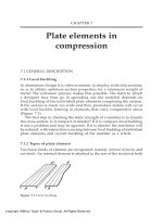
In aluminium design it is often economic to employ wide thin sections,
so as to obtain optimum section properties for a minimum weight of
metal. The extrusion process makes this possible. The limit to which
a designer may thus go in spreading out the material depends on
local buckling of the individual plate elements comprising the section.
If the section is made too wide and thin, premature failure will occur
with local buckles forming in elements that carry compressive stress
(Figure 7.1).
The first step in checking the static strength of a member is to classify
the cross-section. Is it compact or slender? If it is compact, local buckling
is not a problem and may be ignored. If it is slender the resistance will
be reduced, with interaction occurring between local buckling of individual
plate elements and overall buckling of the member as a whole.
7.1.2 Types of plate element
Two basic kinds of element are recognized, namely internal elements and
outstands. An internal element is attached to the rest of the section at both
Figure 7.1 Local buckling.
Copyright 1999 by Taylor & Francis Group. All Rights Reserved.
its longitudinal edges, an outstand at only one (Figure 7.2). In some
lightgauge steel codes, these have been confusingly referred to as
‘restrained’ and ‘unrestrained’ elements.
An element may be subjected to uniform compression (see Section
7.2), as when it forms part of a compression member or of a horizontal
compression flange in a beam. Or it may be under strain gradient as in
a beam web (see Section 7.3). Elements are usually in the form of a
plain flat plate. However, it sometimes pays to improve their stability
by adding a stiffener, in which case they are referred to as reinforced or
stiffened elements (see Section 7.4).
7.1.3 Plate slenderness parameter
The ability of an element to resist local buckling depends on the plate
slenderness parameter ß which is generally taken as:
(7.1)
where b is the flat transverse width of the plate, measured to the springing
of any fillet material, and t its thickness, ß does not depend on the
length a (in the direction of stress) because this has no effect on local
buckling resistance, unless a is very small, i.e. of the same order as b.
7.1.4 Element classification (compact or slender)
In order to classify the cross-section of a member, we first classify its
individual elements, excluding any that may be wholly in tension. The
most adverse classification thus obtained then defines that for the member
as a whole.
For any given type of element there is a critical slenderness ß
s
such
that local buckling failure occurs just as the applied stress reaches the
limiting value p
o
for the material. An element having ß < ß
s
is said to
be compact, since it is fully effective and able to reach p
o
without buckling.
If ß > ß
s
the element will buckle prematurely and only be partially
effective, in which case it is referred to as slender.
Figure 7.2 Basic element types: internal (left) and outstand (right).
Copyright 1999 by Taylor & Francis Group. All Rights Reserved.
(a) Compression member elements
These are simply classified as compact or slender:
ß ß
s
Compact;
ß > ß
s
Slender.
(b) Beam elements
For these the compact classification is subdivided into fully compact
and semi-compact:
ß
ß
f
Fully compact (class 2);
ß
f
< ß ß
s
Semi-compact (class 3);
ß > ß
s
Slender (class 4).
Here ß
f
is a value such that an element is able, not only to attain the
stress p
°
, but also to accept considerably more strain while holding that
stress. Thus, if all the compressed elements in a beam are fully compact,
the section can achieve its full potential moment based on the plastic
section modulus.
Some readers may be more familiar with the terminology used in
Eurocode documents, in which sections are referred to by class numbers,
as shown in brackets under (b) above. (Class 1 comprises elements of
even lower ß than class 2, such that ‘plastic hinges’ are able to operate.
This is of negligible interest in aluminium.)
7.1.5 Treatment of slender elements
The buckling of slender elements is allowed for in design by taking an
effective section, in the same general way as for HAZ softening. The
actual cross-section of the element is replaced by an effective one which
is assumed to perform at full stress, the rest of its area being regarded
as ineffective. In this chapter, we advocate an effective width method for
so doing, in preference to the effective thickness treatment in BS.8118.
The latter is an unrealistic model of what really happens and can produce
unsafe predictions in some situations.
7.2 PLAIN FLAT ELEMENTS IN UNIFORM COMPRESSION
7.2.1 Local buckling behaviour
First we consider elements under uniform compression. Figure 7.3 shows
the typical variation of local buckling strength with slenderness for
internal elements, plotted non-dimensionally, where:
m
=mean stress at
failure, f
°
=0.2% proof stress, E=Young’s modulus, ß=plate slenderness
Copyright 1999 by Taylor & Francis Group. All Rights Reserved.
(see Section 7.1.3). The pattern for outstands is similar, but with a different
ß-scale (about one-third). The scatter shown in the figure results from
random effects including initial out-of-flatness and shape of the stress-
strain curve.
Curve E indicates the stress at which buckling would begin to occur
for an ideal non-welded plate, having purely elastic behaviour and
zero initial out-of-flatness. For very slender plates, this stress, known
as the elastic critical stress (
cr
), is less than the mean applied stress
m
at which the plate actually collapses. In other words, thin plates exhibit
a post-buckled reserve of strength, In the USA the specific terms ‘buckling’
and ‘crippling’ are used to distinguish between
cr
and
m
. The elastic
critical stress
cr
, which is readily found from classical plate theory, is
given by the following well-known expression:
(7.2)
in which the buckling coefficient K may be taken as follows for elements
that are freely hinged along their attached edges or edge:
Internal element K=4
Outstand K=0.41.
It is found that welded plates (i.e. ones with longitudinal edge welds)
perform less well than non-welded plates, with strengths tending to
fall in the lower part of the scatter-band in Figure 7.3. This is due to
HAZ softening, and also the effects of weld shrinkage (locked-in stress,
distortion). Because of the HAZ softening, s
m
for compact welded plates
(low ß) fails to reach f
°
, unlike the performance of non-welded ones.
Figure 7.3 Typical relation between local buckling strength and slenderness for internal
elements, plotted non-dimensionally.
Copyright 1999 by Taylor & Francis Group. All Rights Reserved.
7.2.2 Limiting values of plate slenderness
Table 7.1 lists limiting values of ß
f
and ß
s
needed for the classification
of elements under uniform compression (see Section 7.1.4). These have
been taken from BS.8118 and are expressed in terms of the parameter
given by:
(7.3)
where the limiting stress p
°
is measured in N/mm
2
. This parameter is
needed because ß
f
and ß
s
depend not only on the type of element, but
also on the material properties: the stronger the metal, the more critical
is the effect of buckling. Note that e is roughly equal to unity for 6082-
T6 material or equivalent.
7.2.3 Slender internal elements
For a slender non-welded internal element under uniform compressive
strain, the typical form of the stress pattern at collapse is as shown by
curve 1 in Figure 7.4, with the load mainly carried on the outer parts
of the plate. For design purposes, we approximate to this by taking an
idealized stress pattern 2, comprising equal stress blocks at either edge
which operate at the full stress p
°
with the material in the middle regarded
as ineffective. The width of the two stress blocks is notionally adjusted
to make their combined area equal to that under curve 1. For a non-
welded element, therefore, the assumed effective section is as shown in
diagram N with equal blocks of width b
e1
and thickness t.
A modified diagram is needed if the element contains edge welds.
First, the effective block widths must be decreased to allow for the
adverse effects of weld shrinkage (locked-in stress, greater initial out-
of-flatness). Secondly, an allowance must be made for the effects of
HAZ softening. Diagram W shows the effective section thus obtained
for a welded plate having the same ß. The block widths b
e1
are seen to
Table 7.1 Classification of elements under uniform compression—limiting ß-values
Note: where p
°
is in N/mm
2
.
Copyright 1999 by Taylor & Francis Group. All Rights Reserved.
be less; while in the assumed HAZ a reduced thickness of k
z
t is taken,
where k
z
is the HAZ softening factor (Section 6.4).
For design purposes the effective block width b
e1
can be obtained
from the following general expression:
b
e1
=
1
t (7.4)
in which
1
is a function of ß/ and is as defined by equation (7.3). The
value of
1
may be calculated from the formula:
(7.5)
where =ß/ and P
1
and Q
1
are given in Table 7.2.
Figure 7.6 shows curves of
1
plotted against covering non-welded
and edge-welded plates. Note that this design data, if expressed in
terms of
m,
would produce curves appropriately located (low down) in
the scatter band in Figure 7.3, taking advantage of post-buckled strength
at high ß. It is based on the results of a parametric study by Mofflin,
supported by tests [24], and also those of Little [31].
The above treatment contrasts with the effective thickness approach
in BS.8118. This is a less realistic model, in which the plate is assumed
to be effective over its full width, but with a reduced thickness. When
applied to non-welded plates, it gives the same predictions as ours. But
for welded ones it tends to be unsafe, because it makes an inadequate
correction for HAZ softening, or none at all at high ß.
7.2.4 Slender outstands
We now turn to outstands, again under uniform compression. For a
slender non-welded outstand the stress pattern at collapse will be of
the typical form shown by curve 1 in Figure 7.5, with the load mainly
carried by the material at the inboard edge. The idealized pattern used
in design is indicated by curve 2, with a fully effective stress block next
to this edge and the tip material assumed ineffective. Our effective
section is therefore as shown in figure diagram N (non-welded) or W
(with an edge weld).
The effective block width b
eo
may generally be obtained using a similar
expression to that for internal elements, namely:
b
eo
=
°
t (7.6)
where
°
is again a function of the plate slenderness and is given by
equation (7.3). Here
°
can be calculated from:
(7.7)
where =ß/e, and P
°
and Q
°
are as given in Table 7.2.
Copyright 1999 by Taylor & Francis Group. All Rights Reserved.
Figure 7.4 Slender internal element.
Stress-pattern at failure, and assumed
effective section. N=non-welded,
W=with edge-welds.
Figure 7.5 Slender outstand. Stress-
pattern at failure, and assumed effective
section. N=non-welded, W=welded at
the connected edge.
Table 7.2 Effective section of slender elements—coefficients in the formulae for
1
and
°
Copyright 1999 by Taylor & Francis Group. All Rights Reserved.
Figure 7.7 Outstands, effective width coefficient
°
. N=non-welded, W=welded at con-
nected edge. Broken line relates to strength based on initial buckling (
cr
).
Figure 7.6 Internal elements, effective width coefficient
1
N=non-welded, W=with
edge-welds.
Copyright 1999 by Taylor & Francis Group. All Rights Reserved.
Figure 7.7 shows curves of
°
plotted against , covering the non-
welded and edge-welded cases.
7.2.5 Very slender outstands
By a ‘very slender’ plate element we mean one of high ß that is able to
develop extra strength after the initial onset of buckling (
m
>
cr
) (Figure
7.3). Expressions (7.5) and (7.7) take advantage of the post-buckled reserve
of strength in such elements. In the case of a very slender outstand, such
an approach is sometimes unacceptable, because of the change in the
stress pattern in the post-buckled state, whereby load is shed from the
tip of the outstand to its root (curve 1 in Figure 7.5). The effective minor
axis stiffness of an I-section or channel containing very slender flanges is
thereby seriously reduced, because the flange tips become progressively
less effective as buckling proceeds. Also, with the channel, there is the
possibility of an effective eccentricity of loading, as the centre of resistance
for the flange material moves towards the connected edge. Both effects
tend to reduce the resistance of the member to overall buckling.
When necessary, the designer may allow for these effects by taking
a reduced effective width for very slender outstands, based on initial
buckling (
cr
) rather than
m
. This is effectively achieved by using the
following expression instead of equation (7.7):
(7.8)
which becomes operative when:
Non-welded outstand ß > 12.1
Welded outstand ß > 12.9 .
The effect of so doing is shown by the broken curve in Figure 7.7.
Chapters 8 and 9 explain when it is necessary to use expression (7.8)
rather than (7.7).
With beams, when considering the moment resistance of a local cross-
section (Section 8.2), it is permissible to take advantage of the post-
buckled strength of a very slender outstand and work to the relevant
full line in figure 7.7 (equation (7.7)). But in dealing with LT buckling
of such a member, it may be necessary to assume a reduced effective
section based on initial buckling (
cr
). Refer to Section 8.7.6.
With compression members it is again acceptable to take advantage of
post-buckled strength, when studying failure at a localized cross-section
(Section 9.3). And when considering overall buckling of the member as
a whole, again allowance may have to be made for the loss of stiffness
when the applied stress reaches
cr
. Refer to Sections 9.5.4, 9.6.9.
Copyright 1999 by Taylor & Francis Group. All Rights Reserved.
7.3 PLAIN FLAT ELEMENTS UNDER STRAIN GRADIENT
We now consider the strain-gradient case, covering any element in a beam
that is not parallel to the neutral axis, such as a web or an inclined flange
element. The problem is how to apply the basic local buckling data, as
established for uniform compression, to an element under strain gradient.
7.3.1 Internal elements under strain gradient, general description
First we consider internal elements, for which edges 1 and 2 may be
identified as follows (Figure 7.8):
Edge 1 the more heavily compressed edge;
Edge 2 the other edge.
A parameter
is introduced to describe the degree of strain gradient:
where e
1
and e
2
are the strains arising at the two edges under simple
beam theory (‘plane sections remain plane’). Two cases arise:
1>
>0 inclined flange elements (edge 2 is in compression);
<0 web elements (edge 2 is in tension).
For web elements (
<0), we use the symbol d to denote the plate width,
rather than b, made up of widths d
c
in compression and d
t
in tension.
The plate slenderness ß is now taken as follows:
Figure 7.8 Internal elements under strain gradient. NA=neutral axis.
Copyright 1999 by Taylor & Francis Group. All Rights Reserved.
(7.9a)
(7.9b)
The strain gradient case is always more favourable than that of uniform
compression (
=1), because the peak strain only arises at one point in
the width of the element, namely at edge 1. The strain at this point at
the onset of buckling is higher than it would be for a uniformly compressed
element of the same ß. Also the buckled shape is asymmetric, with the
maximum depth of buckle occurring nearer to edge 1 than edge 2.
The elastic critical stress
cr
, which now refers to the stress at edge
1, is a function of
. It may be calculated [25] from the standard expression
(7.2) with K found from the following empirical formulae (plotted in
figure 7.9), which are close enough to the exact theory:
1>
>0 K=4{1+(1-
)
1.5
) (7.10a)
<0 K=6+2(1–
)
-6
(7
.
10b)
7.3.2 Internal elements under strain gradient, classification
The limiting plate slenderness ß
f
or ß
s
, needed for element classification,
has the same meaning as before (Section 7.1.4). But the actual values in the
Figure 7.9 Internal elements under strain gradient, elastic buckling coefficient K.
Copyright 1999 by Taylor & Francis Group. All Rights Reserved.
strain-gradient case will be higher than for uniform compression. They
may be read from the relevant curve in Figure 7.10, the equations to
which are given in Table 7.3. Classification obtained in this manner
agrees well with BS.8118.
In entering the figure,
should be based on the beam’s plastic
neutral axis (equal area axis) for finding ß
f
and on the elastic axis
Figure 7.10 Internal elements under strain gradient, limiting values of ß/ . Non-welded:
ß
f
=curve B; ß
s
=curve C. Edge-welded: ßf=curve A; ß
s
=curve B.
Table 7.3 Classification of plate elements under strain gradient—formulae for the limiting
values of ß
Notes. 1. Outstands: case T=peak compression at tip, case R=peak compression at root.
2.
where p
°
is in N/mm
2
.
3. g=0.7+0.3
for
>-1; =0.8/(1-
) for
<-1.
Copyright 1999 by Taylor & Francis Group. All Rights Reserved.
(through the centroid) for ß
S
. For convenience, the neutral axis may
be based on the gross section when classifying the section. But when
subsequently calculating the section properties, an effective section
must be taken.
7.3.3 Slender internal elements under strain gradient
For a slender element under strain-gradient it is logical to assume that
the stress blocks comprising its effective section are unequal. The block
at edge 2 should be made wider than that at edge 1, thus reflecting the
asymmetry of the buckled form. In our method, the two block-widths
are found as follows (Figure 7.11).
(a) Inclined flange element (1>
>0)
b
e1
=
1
+ t (7.11a)
b
e2
=(1.4-0.4
)b
e1
(7.11b)
where
1
is found from equation (7.5), or Figure 7.6, still taking =ß/ .
(b) Web element (
<0)
The total element is divided into regions of compression (dc) and tension
(d
t
). Block 2 is assumed to occupy all of d
t
plus an amount d
e2
of d
c
as
shown, and we take:
d
e1
=
1
t (7.12a)
d
e2
=1.4d
e1
(7.12b)
Figure 7.11 Internal elements under strain gradient, assumed effective section.
Copyright 1999 by Taylor & Francis Group. All Rights Reserved.
where
1
is again found from equation (7.5), or Figure 7.6, but now
putting:
(7.13)
If an element has edge welds, a reduced thickness k
z
t is taken in each
HAZ region in the same way as for uniform compression (i.e. the areas
X in the figure are removed).
7.3.4 Outstands under strain gradient, general description
Now we turn to outstands, for which there are two possible cases of
strain gradient (Figure 7.12):
Case T peak compression is at the tip;
Case R peak compression is at the root.
In either case, the more heavily compressed edge is called edge 1 as
before. And again we use
(=e
2
/e
1
) to specify the degree of strain gradient.
The buckling of an outstand is mainly governed by what happens at
the tip. Therefore, case T is only slightly more favourable than uniform
compression, since the effect of
is merely to decrease the stress in the
relatively stable material close to the supported edge. But case R is
clearly more favourable, because
now directly affects the tip stress
which is what matters.
The elastic critical stress
cr
(occurring at edge 1) for a simply
supported outstand under strain gradient may be found from the
standard equation (7.2), taking a suitable value for K. Figure 7.13 shows
how K varies with
for the two cases, the curves being plotted from
the following empirical expressions which give a good approximation
to the rigorous values:
Case T K=0.41 for 1 >
> 0.5
=0.50–0.18
for
< 0.5 (7.14a)
Case R K=0.41+1.3(1-
)
4
(7.14b)
Figure 7.12 Outstands under strain-gradient. Cases T and R.
Copyright 1999 by Taylor & Francis Group. All Rights Reserved.
7.3.5 Outstands under strain gradient, case T
For an outstand under case T loading, it is reasonable in design to
ignore the slight improvement in performance as compared with uniform
compression. The value of ß
f
or ß
s
needed for classification, and likewise
the effective block width b
eo
when the element is slender, may thus be
taken using the data already provided for the case
=1 (Sections 7.2.2
and 7.2.4).
7.3.6 Outstands under strain gradient, case R
With case R loading, the above approach would be unduly pessimistic.
Instead we follow BS.8118 and introduce the parameter g given by:
1 >
> -1 g=0.7+0.3
(7.15a)
(7.15b)
Classification then consists of comparing ß (= b/t) with modified values
of ß
f
and ß
s
obtained by dividing the uniform compression values (Table
Figure 7.13 Outstands under strain-gradient, elastic buckling coefficient K.
Copyright 1999 by Taylor & Francis Group. All Rights Reserved.
7.1) by g. The resulting design curves of ß
f
and ß
s
plotted against
are
given in Figure 7.14, the corresponding equations being included in
Table 7.3. Again we base
on the plastic neutral axis of the section
when finding ß
f
, and on the elastic one for ß
s
.
When the outstand is slender the effective block width b
eo
is found
from the following expression:
(7.16)
where
°
is again found from equation (7.7) or Figure 7.7, but now
putting:
(7.17)
7.4 REINFORCED ELEMENTS
7.4.1 General description
The local buckling performance of a thin element can often be improved
[25] by reinforcing it with a longitudinal stiffener, as shown in Figure 7.15.
Figure 7.14 Outstands under strain-gradient (case R), limiting values of ß/ . Non-welded:
ß
f
=curve B; ß
s
=curve C. Welded: ß
f
=curve A; ß
s
=curve B.
Copyright 1999 by Taylor & Francis Group. All Rights Reserved.
This can take the form of an integrally extruded addition such as a rib,
lip or bulb, or in a sheet metal component the reinforcement can be
rolled in as a flute or lip. Very small stiffeners do nothing for plate
stability, but larger ones are beneficial.
The problem is how to adapt the data provided for plain elements
(Sections 7.2, 7.3) to stiffened ones. The BS.8118 method (effective thickness)
is based on a study of the elastic buckling of such elements made by
Bulson in the 1950s [25]. Our treatment basically follows this, but is
presented in terms of effective width.
7.4.2 Limitations on stiffener geometry
The treatment assumes that a reinforced plate will buckle in the mode
shown in Figure 7.16 taking the stiffener with it. For this assumption to
be valid, the stiffener should be so proportioned as to be at least semi-
compact when considered as an outstand element on its own (Table
7.1); otherwise it will itself buckle prematurely. If the reinforced element
is to be classified as fully compact, then the stiffener must be fully
compact too.
A further constraint arises in the case of beam flanges. Research by
J.Rhodes at Glasgow University on light-gauge cold-rolled steel showed
that a lipped outstand element forming the compression flange of a beam
tends to be much less stable when the lip is outward facing. Some steel
codes, therefore, require that the presence of any outward facing
reinforcement should be ignored when considering the stability of such
an element. A blanket restriction of this kind is unduly severe for aluminium,
since the extrusion process enables one to design ‘chunkier’ reinforcement
Figure 7.15 Reinforced elements.
Figure 7.16 Assumed failure mode for reinforced elements.
Copyright 1999 by Taylor & Francis Group. All Rights Reserved.
than that which is possible in a cold-rolled section. A square rib or a
bulb will never become torsionally unstable, and can be safely located
facing outwards. Unfortunately, no data exist as to the limiting lip
geometry at which outward facing reinforcement in a beam flange begins
to become unsatisfactory.
7.4.3 ‘Standard’ reinforcement
‘Standard’ reinforcement comprises a plain single-sided stiffener of
thickness t equal to that of the plate (Figure 7.17), the stiffener height
c being measured from the near surface of the plate. The design data
given below apply directly to an element stiffened thus.
For any other shape of stiffener, it is necessary to notionally replace
the actual stiffener by an equivalent one of standard form, whose height
c is such as to make its inertia about the mid-plane of the plate the
same as that of the actual stiffener. The stability of the reinforced element
is then assessed as if it had a standard stiffener with this c. Note that
the equivalent standard stiffener is always taken as single-sided, even
if the actual reinforcement is double-sided.
7.4.4 Location of the stiffener
(a) Internal elements under uniform compression
The stiffener is assumed to be at midwidth.
(b) Internal elements under strain gradient
We define edges 1, 2 and the parameter ? in the same way as for the
unreinforced case. It is clearly desirable to place the stiffener nearer
to edge 1 than edge 2, so we assume it is located at an optimum distance
j from edge 1 (Figure 7.18) given by:
Figure 7.17 ‘Standard’ reinforcement.
Copyright 1999 by Taylor & Francis Group. All Rights Reserved.
(7.18a)
(7.18b)
(c) Outstands
The reinforcement is assumed to be at the free edge.
7.4.5 Modified slenderness parameter
The essential step in dealing with reinforced elements is to replace the
usual slenderness parameter ß (=b/t or d
c
/t) by a modified value ß’,
defined as follows for an element having standard reinforcement:
(7.19a)
(7.19b)
where b is the total width or dc the width in compression. The factors
(ജ 1) are a measure of the stabilizing effect of the reinforcement, and
may be read from Figure 7.19 taking c as defined in Figure 7.17. Alternatively,
may be calculated from an equivalent equation (valid for c/t>1):
Figure 7.18 Stiffener location for internal elements under strain gradient.
Copyright 1999 by Taylor & Francis Group. All Rights Reserved.
(7.20a)
(7.20b)
When c ഛ t the value of p is taken as unity, because the reinforcement
then provides no benefit.
With non-standard reinforcement, the procedure is to find c for the
equivalent standard stiffener and then determine as above.
7.4.6 Classification
The classification (Section 7.1.4) of reinforced elements is performed
simply by relating ß’ (instead of ß) to the appropriate limiting value
used for plain elements, In other words, ß’ is compared with ß
f
or ß
s
as
given by:
Uniform compression Table 7.1
Strain gradient, internal element Figure 7.10
Strain gradient, outstand Figure 7.14
For elements found to be fully or semi-compact, the full area is effective,
including that of the stiffener, except where a local reduction is made
at a welded edge to allow for HAZ softening.
Figure 7.19 Slenderness adjustment factor for reinforced elements: internal elements
outstands
0
.
Copyright 1999 by Taylor & Francis Group. All Rights Reserved.
7.4.7 Slender reinforced elements
The following treatment applies to slender elements having standard
reinforcement. With other forms of reinforcement, it is recommended
that the load carrying capacity should be based on that of an element
having equivalent standard reinforcement (Section 7.4.3).
There are two possible patterns (A, B) for the effective section of
such elements, as depicted in Figures 7.20 and 7.21:
Pattern A All the plate is effective, and also a width c
e
of the
stiffener next to it;
Pattern B The effective section comprises two stress blocks within
the plate (for an internal element) or one such stress
block (for an outstand).
Pattern A applies for elements in which ß’ is only a bit over ß
s
, and
pattern B for more slender ones.
Figure 7.20 Slender reinforced internal elements, effective areas.
Figure 7.21 Slender reinforced outstands, effective area.
Copyright 1999 by Taylor & Francis Group. All Rights Reserved.
Table 7.4 provides expressions which enable the stress block width
or widths for pattern B to be found directly for the various cases. When
the total effective width thus calculated exceeds the plate width, this
means that pattern B no longer applies and pattern A becomes valid
instead. The ‘overflow’ then defines the width of the effective part of
the stiffener. In other words, c
e
in pattern A is taken as the amount by
which the total effective width, as calculated using the pattern B formulae,
exceeds the actual plate width.
It will be seen that the pattern B formulae involve the coefficient
1
or
0
which may be calculated from equation (7.5) or (7.7), or read from
Figure 7.6 or 7.7. In so doing, the parameter should be taken as in the
last column of the table.
If an element is welded along its connected edge or edges a reduced
thickness of k
z
t is taken in the HAZ, as usual.
Table 7.4 Slender reinforced elements, effective width formulae
Notes: 1. Refer to Figures 7.20, 7.21.
2.
is as defined in Section 7.3.1.
3.
1
and
0
are found by entering the relevant curve in Figure 7.6 or 7.7 at the value of listed in
final column.
4.
1
,
0
and ß’ are as defined in Section 7.4.5.
5.
where
0
is in N/mm2.
6. g=0.7+0.3
for
-1,=0.8/(1-
) for
Ͻ
-1
Copyright 1999 by Taylor & Francis Group. All Rights Reserved.