Basic Theory of Plates and Elastic Stability - Part 27 docx
Bạn đang xem bản rút gọn của tài liệu. Xem và tải ngay bản đầy đủ của tài liệu tại đây (514.69 KB, 28 trang )
Soong, T.T. and Dargush, G.F. “Passive Energy Dissipation and Active Control”
Structural Engineering Handbook
Ed. Chen Wai-Fah
Boca Raton: CRC Press LLC, 1999
PassiveEnergyDissipationand
ActiveControl
T.T.Soongand
G.F.Dargush
DepartmentofCivilEngineering,
StateUniversityofNewYork
atBuffalo,Buffalo,NY
27.1Introduction
27.2BasicPrinciplesandMethodsofAnalysis
Single-Degree-of-FreedomStructuralSystems
•
Multi-
Degree-of-FreedomStructuralSystems
•
EnergyFormulations
•
Energy-BasedDesign
27.3RecentDevelopmentandApplications
PassiveEnergyDissipation
•
ActiveControl
27.4CodeDevelopment
27.5ConcludingRemarks
References
27.1 Introduction
Inrecentyears,innovativemeansofenhancingstructuralfunctionalityandsafetyagainstnatural
andman-madehazardshavebeeninvariousstagesofresearchanddevelopment.Byandlarge,they
canbegroupedintothreebroadareas,asshowninTable27.1:(1)baseisolation,(2)passiveenergy
dissipation,and(3)activecontrol.Ofthethree,baseisolationcannowbeconsideredamoremature
technologywithwiderapplicationsascomparedwiththeothertwo[2].
TABLE27.1 StructuralProtectiveSystems
Seismic Passiveenergy
isolation dissipation Activecontrol
Elastomericbearings Metallicdampers Activebracingsystems
Frictiondampers Activemassdampers
Leadrubberbearings Viscoelasticdampers Variablestiffness
ordampingsystems
Viscousfluiddampers
Slidingfrictionpendulum Tunedmassdampers
Tunedliquiddampers
Passiveenergydissipationsystemsencompassarangeofmaterialsanddevicesforenhancing
damping,stiffness,andstrength,andcanbeusedbothfornaturalhazardmitigationandforreha-
bilitationofagingordeficientstructures[46].Inrecentyears,seriouseffortshavebeenundertaken
todeveloptheconceptofenergydissipation,orsupplementaldamping,intoaworkabletechnology,
andanumberofthesedeviceshavebeeninstalledinstructuresthroughouttheworld.Ingeneral,
c
1999byCRCPressLLC
such systems are characterized by a capability to enhance energy dissipation in the structural systems
in which they are installed. This effect may be achieved either by conversion of kinetic energy to heat
or by transferring of energy among vibrating modes. The first method includes devices that operate
on principles such as frictional sliding, yielding of metals, phase transformation in metals, defor-
mation of viscoelastic solids or fluids, and fluid orificing. The latter method includes supplemental
oscillators that act as dynamic absorbers. A list of such devices that have found applications is given
in Table 27.1.
Among the current passive energy dissipation systems, those based on deformation of viscoelastic
polymers and on fluid orificing represent technologies in which the U.S. industry has a worldwide
lead. Originally developed for industrial and military applications, these technologies have found
recent applications in natural hazard mitigation in the form of either energy dissipation or elements
of seismic isolation systems.
The possible use of active control systems and some combinations of passive and active systems,
so-called hybrid systems, as a means of structural protection against wind and seismic loads has
also received considerable attention in recent years. Active/hybrid control systems are force delivery
devices integrated with real-time processing evaluators/controllers and sensors within the structure.
They must react simultaneously with the hazardous excitation to provide enhanced str uctural be-
havior for improved service and safety. Figure 27.1 is a block diagram of the active structural control
problem. The basic task is to find a control strategy that uses the measured structural responses to
FIGURE 27.1: Block diagram of active structural control.
calculate the control signal that is appropriate to send to the actuator. Structural control for civil
engineering applications has a number of distinctive features, largely due to implementability issues,
that setit apart from thegeneral fieldof feedback control. First ofall, when addressing civil structures,
there is considerable uncertainty, including nonlinearity, associated with bothphysical properties and
disturbances such as earthquakes and wind. Additionally, the scale of the forces involved is quite
large, there are a limited number of sensors and actuators, the dynamics of the actuators can be quite
complex, and the systems must be fail safe [10, 11, 23, 24, 27, 44].
Nonetheless, remarkable progress has been made over the last 20 years in research on using ac-
tive and hybrid systems as a means of structural protection against wind, earthquakes, and other
hazards [45, 47]. Research to date has reached the stage where active systems such as those listed in
Table 27.1 have been installed in full-scale structures. Some active systems are also used temporarily
in construction of bridges or large span structures (e.g., lifelines, roofs) where no other means can
provideadequate protection. Additionally, mostof thefull-scalesystemshave been subjected to actual
c
1999 by CRC Press LLC
wind forces and ground motions, and their observed performances provide invaluable information
in terms of (1) validating analytical and simulation procedures used to predict system performance,
(2) verifying complex electronic-digital-servohydraulic systems under actual loading conditions, and
(3) verifying the capability of these systems to operate or shutdown under prescribed conditions.
The focus of this chapter is on passive energy dissipation and active control systems. Their basic
operating principles and methods of analysis are given in Section 27.2,followedbyareviewinSec-
tion 27.3 of recent development and applications. Code development is summarized in Section 27.4,
and some comments on possible future directions in this emerging technological area are advanced
in Section 27.5. In the following subsections, we shall use the term structural protective systems to
represent either passive energy dissipation systems or active control systems.
27.2 Basic Principles and Methods of Analysis
With recent development and implementation of modern structural protective systems, the entire
structural engineering discipline is now undergoing a major change. The traditional idealization of
a building or bridge as a static entity is no longer adequate. Instead, st ructures must be analyzed and
designed by considering their dynamic behavior. It is with this in mind that we present some basic
concepts related to topics that are of primary importance in understanding, analyzing, and designing
structures that incorporate structur al protective systems.
In what follows, a simple single-degree-of-freedom (SDOF) structural model is discussed. This
represents the prototype for dynamic behavior. Particular emphasis is given to the effect of damp-
ing. As we shall see, increased damping can significantly reduce system response to time-varying
disturbances. While this model is useful for developing an understanding of dynamic behavior, it
is not sufficient for representing real structures. We must include more detail. Consequently, a
multi-degree-of-freedom (MDOF) model is then int roduced, and several numerical procedures are
outlined for general dynamic analysis. A discussion comparing typical damping characteristics in
traditional and control-augmented structures is also included. Finally, a treatment of energy for-
mulations is provided. Essentially one can envision an environmental disturbance as an injection of
energy into a structure. Design then focuses on the management of that energy. As we shall see, these
energy concepts are particularly relevant in the discussion of passively or actively damped structures.
27.2.1 Single-Degree-of-Freedom Structural Systems
Consider the lateral motion of the basic SDOF model, shown in Figure 27.2, consisting of a mass,
m, supported by springs with total linear elastic stiffness, k, and a damper with linear viscosity, c.
This SDOF system is then subjected to an external disturbance, characterized by f(t). The excited
model responds with a lateral displacement, x(t), relative to the ground, which satisfies the equation
of motion:
m ¨x + c ˙x +kx = f(t)
(27.1)
in which a superposed dot represents differentiation with respect to time. For a specified input, f(t),
and with known structural parameters, the solution of this equation can be readily obtained.
In the above, f(t)represents an arbitrary environmental disturbance such as wind or an earth-
quake. In the case of an earthquake load,
f(t) =−m¨x
g
(t) (27.2)
where ¨x
g
(t) is ground acceleration.
Consider now the addition of a generic passive or active control element into the SDOF model, as
indicated in Figure 27.3. The response of the system is now influenced by this additional element.
c
1999 by CRC Press LLC
FIGURE 27.2: SDOF model.
FIGURE 27.3: SDOF model with passive or active control element.
The symbol in Figure 27.3 represents a generic integrodifferential operator, such that the force
corresponding to the control device is written simply as x. This permits quite general response
characteristics, including displacement, velocity, or acceleration-dependent contributions, as well as
hereditary effects. The equation of motion for the extended SD OF model then becomes, in the case
of an earthquake load,
m ¨x + c ˙x +kx +x =−
(
m +
m
)
¨x
g
(27.3)
with m representing the mass of the control element.
The specific form of x needs to be specified before Equation 27.3 can be analyzed, which is
necessarily highly dependent on the device type. For passive energy dissipation systems, it can be
c
1999 by CRC Press LLC
represented by a force-displacement relationship such as the one shown in Figure 27.4, representing
a rate-independent elastic-perfectly plastic element. For an active control system, the form of x
FIGURE 27.4: Force-displacement model for elastic-perfectly plastic passive element.
is governed by the control law chosen for a given application. Let us first note that, denoting the
control force applied to the structure in Figure 27.1 by u(t ), the resulting dynamical behavior of the
structure is governed by Equation 27.3 with
x =−u(t)
(27.4)
Suppose that a feedback configuration is used in which the control force, u(t), is designed to be a
linear function of measured displacement, x(t), and measured velocity, ˙x(t). The control force, u(t),
takes the form
u(t) = g
1
x(t) +g
2
˙x(t) (27.5)
In view of Equation 27.4,wehave
x =−
[
g
1
+ g
2
d/dt
]
x (27.6)
The control law is, of course, not necessarily linear in x(t) and ˙x(t) as given by Equation 27.5.In
fact, nonlinear control laws may be more desirable for civil engineering applications [61]. Thus, for
both passive and active control cases, the resulting Equation 27.3 can be highly nonlinear.
Assume for illustrative purposes that the base structure has a viscous damping ratio ζ = 0.05 and
that a simple massless yielding device is added to serve as a passive element. The force-displacement
relationship for this element, depicted in Figure 27.4, is defined in terms of an initial stiffness,
¯
k,
and a yield force,
¯
f
y
. Consider the case where the passively damped SDOF model is subjected to the
1940 El Centro S00E ground motion as shown in Figure 27.5. The initial stiffness of the elastoplastic
passive device is specified as
k = k, while the yield force, f
y
, is equal to 20% of the maximum applied
ground force. That is,
f
y
= 0.20 Max
m
¨x
g
(27.7)
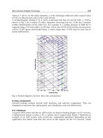
The resulting relative displacement and total acceleration time histories are presented in Figure 27.6.
There is significant reduction in response compared to that of the base structure without the control
element, as shown in Figure 27.7. Force-displacement loops for the viscous and passive elements are
displayed in Figure 27.8. In this case, the size of these loops indicates that a significant portion of the
energy is dissipated in the control device. This tends to reduce the forces and displacements in the
primary structural elements, which of course is the purpose of adding the control device.
c
1999 by CRC Press LLC
FIGURE 27.5: 1940 El Centro S00E accelerogram.
FIGURE 27.6: 1940 ElCentrotimehistory responsefor SDOF with passiveelement: (a) displacement,
(b) acceleration.
27.2.2 Multi-Degree-of-Freedom Structural Systems
In light of the preceding arguments, it becomes imperative to accurately characterize the behavior
of any control device by constructing a suitable model under time-dependent loading. Multiaxial
representations may be required. Once that model is established for a device, it must be properly
incorporatedintoamathematicalidealizationoftheoverallstructure. Seldom is it sufficient to employ
an SDOF idealization for an actual structure. Thus, in the present subsection, the formulation for
dynamic analysis is extended to an MDOF representation.
c
1999 by CRC Press LLC
FIGURE 27.7: 1940 El Centro SDOF time history response: (a) displacement, (b) acceleration.
FIGURE 27.8: 1940 El Centro SDOF force-displacement response for SDOF with passive element:
(a) viscous element, (b) passive element.
The finite element method (FEM) (e.g., [63]) currently provides the most suitable basis for this
formulation. From a purely physical viewpoint, each individual structural member is represented
mathematically by one or more finite elements having the same mass, stiffness, and damping charac-
teristics as the original member. Beams and columns are represented by one-dimensional elements,
while shear walls and floor slabs are idealized by employing two-dimensional finite elements. For
more complicated or critical structural components, complete three-dimensional models can be
developed and incorporated into the overall structural model in a straightforward manner via sub-
structuring techniques.
The FEM actually was developed largely by civil engineers in the 1960s from this physical perspec-
tive. However, during the ensuing decades the method has also been given a rigorous mathematical
foundation, thus permitting the calculation of error estimates and the utilization of adaptive solu-
tion strategies (e.g., [49]). Additionally, FEM formulations can now be derived from variational
principles or Galerkin weighted residual procedures. Details of these formulations are beyond our
scope. However, it should be noted that numerous general-purpose finite element software pack-
c
1999 by CRC Press LLC
ages currently exist to solve the structural dynamics problem, including ABAQUS, ADINA, ANSYS,
and MSC/NASTRAN. While none of these programs specifically addresses the special formulations
needed to characterize structural protective systems, most permit generic user-defined elements.
Alternatively, one can utilize packages geared exclusively toward civil engineer ing structures, such as
ETABS, DRAIN, andIDARC, which in some cases can already accommodate typical passive elements.
Via any oftheabove-mentionedmethods andprograms, the displacement responseof thestructure
is ultimately represented by a discrete set of variables, which can be considered the components of a
generalized relative displacement vector, x(t), of dimension N. Then, in analogy with Equation 27.3,
the N equations of motion for the discretized structural system, subjected to uniform base excitation
and time varying forces, can be written:
M ¨x +C ˙x + Kx + x =−(M +
M)¨x
g
(27.8)
where M, C, and K represent the mass, damping, and stiffness matrices, respectively, while sym-
bolizes a matrix of operators that model the protective system present in the structure. Meanwhile,
the vector ¨x
g
contains the rigid body contribution of the seismic ground displacement to each degree
of freedom. The matrix
M represents the mass of the protective system.
There are several approaches that can be taken to solve Equation 27.8. The preferred approach, in
terms of accuracy and efficiency, depends upon the form of the various terms in that equation. Let us
first suppose that the protective device can be modeled as direct linear functions of the acceleration,
velocity, and displacement vectors. That is,
x =
M ¨x +
C ˙x + Kx (27.9)
Then, Equation 27.8 can be rewritten as
ˆ
M ¨x +
ˆ
C ˙x +
ˆ
Kx =−
ˆ
M ¨x
g
(27.10)
in which
ˆ
M = M +
M (27.11a)
ˆ
C = C +
C (27.11b)
ˆ
K = K +
K (27.11c)
Equation 27.10 is now in the form of the classical matrix structural dynamic analysis problem. In the
simplest case, which we will now assume, all of the matrix coefficients associated with the primary
structure and the passive elements are constant. As a result, Equation 27.10 represents a set of N
linear second-order ordinary differential equations with constant coefficients. These equations are,
in general, coupled. Thus, depending upon N, the solution of Equation 27.10 throughout the time
range of interest could become computationally demanding. This required effort can be reduced
considerably if the equation can be uncoupled via a transformation; that is, if
ˆ
M,
ˆ
C, and
ˆ
K can be
diagonalized. Unfortunately, this is not possible for arbitrary matrices
ˆ
M,
ˆ
C, and
ˆ
K. However, with
certain restrictions onthe dampingmatrix,
ˆ
C, thetransformation to modal coordinatesaccomplishes
the objective via the modal superposition method (see, e.g., [7]).
As mentioned earlier, it is more common having x in Equation 27.9 nonlinear in x for a variety of
passive and active control e lements. Consequently, it is important to develop alternative numerical
approaches and design methodologies applicable to more generic passively or actively damped struc-
tural systems governed by Equation 27.8. Direct time-domain numerical integration algorithms are
most useful in that regard. The Newmar k beta algorithm, for example, is one of these algorithms
and is used extensively in structural dynamics.
c
1999 by CRC Press LLC
27.2.3 Energy Formulations
In the previous two subsections, we have considered SDOF and MDOF str uctural systems. The
primary thrust of our analysis procedures has been the determination of displacements, velocities,
accelerations, and forces. These are the quantities that, historically, have been of most interest.
However, with the advent of innovative concepts for structural design, including structural protective
systems, it is impor tant to rethink current analysis and design methodologies. In particular, a focus
on energy as a design criterion is conceptually very appealing. With this approach, the engineer is
concerned, not so much with the resistance to lateral loads but rather, with the need to dissipate the
energy input into thestructure from environmental disturbances. Actually, this energy concept is not
new. Housner [21] suggested an energy-based desig n approach even for more traditional structures
several decades ago. The resulting formulation is quite appropriate for a general discussion of energy
dissipation in structures equipped with structural protective systems.
In what follows, an energy formulation is developed for an idealized structural system, which may
include one or more control devices. The energy concept is ideally suited for application to non-
traditional structures employing control elements, sincefor thesesystemsproperenergy management
is a key to successful design. To conser ve space, only SDOF structural systems are considered, which
can be easily generalized to MDOF systems.
Consider once again the SDOF oscillator shown in Figure 27.2 and governed by the equation
of motion defined in Equation 27.1. An energ y representation can be formed by integrating the
individual force terms in Equation 27.1 over the entire relative displacement history. The result
becomes
E
K
+ E
D
+ E
S
= E
I
(27.12)
where
E
K
=
m ¨xdx =
m ˙x
2
2
(27.13a)
E
D
=
c ˙xdx =
c ˙x
2
dt (27.13b)
E
S
=
kxdx =
kx
2
2
(27.13c)
E
I
=
fdx (27.13d)
The individual contributions includedon theleft-hand side ofEquation 27.12 represent the relative
kinetic energy of the mass (E
K
), the dissipative energy caused by inherent damping within the
structure (E
D
), and the elastic strain energy (E
S
). The summation of these energies must balance
the input energy (E
I
) imposed on the structure by the external disturbance. Note that each of the
energy terms is actually a function of time, and that the energy balance is required at each instant
throughout the duration of the loading.
Consider aseismic design as a more representative case. It is unrealistic to expect that a tradi-
tionally designed structure will remain entirely elastic during a major seismic disturbance. Instead,
inherent ductility of structures is relied upon to prevent catastrophic failure, while accepting the fact
that some damage may occur. In such a case, the energy input (E
I
) from the earthquake simply
exceeds the capacity of the structure to store and dissipate energy by the mechanisms specified in
Equations 27.13a–c. Once this capacity is surpassed, portions of the structure typically yield or crack.
The stiffness is then no longer a constant, and the spring force in Equation 27.1 must be replaced
by a more general functional relation, g
S
(x), which will commonly incorporate hysteretic effects. In
c
1999 by CRC Press LLC
general, Equation 27.13c is redefined as follows for inelastic response:
E
S
=
g
S
(x)dx = E
S
e
+ E
S
p
(27.14)
in which E
S
is assumed separable into additive contributions E
S
e
and E
S
p
, representing the fully
recoverable elastic strain energy and the dissipative plastic strain energy, respectively.
Figure 27.9a provides the energy response of a 0.3-scale, six-story concentrically braced steel
structure as measured by Uang and Bertero [54]. The seismic input consisted of the 1978 Miyagi-
FIGURE 27.9: Energy response of a traditional structure: (a) damageability limit state, (b) collapse
limit state. (From Uang, C.M. and Bertero, V.V. 1986. Earthquake Simulation Tests and Associated
Studies of a 0.3 Scale Model of a Six-Story Concentrically Braced Steel Structure. Report No. UCB/
EERC - 86/10, Earthquake Engineering Research Center, Ber keley, CA. With permission.)
Ken-Oki Earthquake signal scaled to produce a peak shaking table acceleration of 0.33 g, which was
deemed to represent the damageability limit state of the model. At this level of loading, a significant
portion of the energy input to the structure is dissipated, with both viscous damping and inelastic
hysteretic mechanisms having substantial contributions. If the intensity of the signal is elevated, an
even greater share of the energy is dissipated via inelastic deformation. Finally, for the collapse limit
state of this model structure at 0.65 g peak table acceleration, approximately 90% of the energy is
consumed by hysteretic phenomena, as shown in Figure 27.9b. Evidently, the consumption of this
quantity of energy has destroyed the structure.
From an energy perspective, then, for proper aseismic design, one must attempt to minimize the
amount of hysteretic energy dissipated by the structure. There are basically two viable approaches
available. The first involves designs that result in a reduction in the amount of energy input to the
structure. Base isolation systems and some active control systems, for example, fall into that category.
The second approach, as in the passive and active control system cases, focuses on the introduction of
additional energy-dissipating mechanisms into the structure. These devices are designed to consume
a portion of the input energy, thereby reducing damage to the main structure caused by hysteretic
dissipation. Naturally, for a large earthquake, the de vices must dissipate enormous amounts of
energy.
The SDOF system with a control element is displayed in Figure 27.3, while the governing inte-
grodifferential equation is provided in Equation 27.3. After integrating with respect to x, an energy
balance equation can be written:
E
K
+ E
D
+ E
S
e
+ E
S
p
+ E
C
= E
I
(27.15)
c
1999 by CRC Press LLC
where the energy associated with the control element is
E
C
=
xdx (27.16)
and the other terms are as previously defined.
As an example of the effects of control devices on the energy response of a structure, consider the
tests, of a one-third scale three-story lightly reinforced concrete framed building, conducted by Lobo
et al. [30]. Figure 27.10a displays the measured response of the structure due to the scaled 1952 Taft
N21E earthquakesignal normalized forpeakground accelerations of 0.20g. Aconsiderablepor tion of
FIGURE27.10: Energy response of teststructure: (a) without passivedevices, (b) withpassive devices.
(From Lobo, R.F., Bracci, J.M., Shen, K.L., Reinhorn, A.M.,andSoong., T.T.1993. Ear thquake Spectra,
9(3), 419-446. With permission.)
the input energy is dissipated via hysteretic mechanisms, which tend to damage the primary structure
through cracking and the formation of plastic hinges. On the other hand, damage is minimal with
the addition of a set of viscoelastic braced dampers. The energy response of the braced structure,
due to the same seismic signal, is shown in Figure 27.10b. Notice that although the input energy
has increased slightly, the dampers consume a significant portion of the total, thus protecting the
primary structure.
27.2.4 Energy-Based Design
While the energy concept, as outlined briefly above, does not currently provide the basis for aseismic
design codes, there is a considerable body of knowledge that has been developed from its application
to traditional structures. Housner [21, 22] was the first to propose an energy-based philosophy
for earthquake-resistant design. In particular, he was concerned with limit design methods aimed
toward preventing collapse of structures in seismically active regions. Housner assumed that the
energy input calculated for an undamped, elastic idealization of a structure provided a reasonable
upper bound to that for the actual inelastic structure.
Berg and Thomaides [4] examined the energy consumption in SDOF elastoplastic structures via
numerical computation and developed energy input spectra for several strong-motion earthquakes.
These spectra indicate that the amount of energy, E
I
, imparted to a structure from a given seismic
event is quite dependent upon the structure itself. The mass, the natural period of vibration, the
critical damping ratio, and yield force level were all found to be important characteristics.
c
1999 by CRC Press LLC
On theother hand, theirresults did suggest thatthe establishmentof upperbounds forE
I
might be
possible, and thus provided support for the approach introduced by Housner. However, the energy
approach was largely ignored for a number of years. Instead, limit state design methodologies were
developed which utilized the concept of displacement ductility to construct inelastic response spectra
as proposed initially by Veletsos and Newmark [56].
More recently, there has been a resurgence of interest in energy-based concepts. For example,
ZahrahandHall[62]developedanMDOFenergy formulationandconductedanextensiveparametric
study of energy absorption insimple structural frames. Their numerical work includeda comparison
between energy-based and displacement ductility-based assessments of damage, but the authors
stopped short of issuing a general recommendation.
A critical assessment of the energy concept as a basis for design was provided by Uang and Bert-
ero [55]. The authors initially contrast two alternative definitions of the seismic input energy. The
quantity specified in Equation 27.13d is labeled the relative input energy, while the absolute input
energy (E
I
a
) is defined by
E
I
a
=
m ¨x
t
dx
g
(27.17a)
In conjunction with this latter quantity, an absolute kinetic energy (E
K
a
) is also required, where
E
K
a
=
m ˙x
2
t
2
(27.17b)
The absolute energy equation corresponding to Equation 27.15 then becomes
E
K
a
+ E
D
+ E
S
e
+ E
S
p
+ E
C
= E
I
a
(27.18)
Based upon the development of input energy spectra for an SDOF system, the authors conclude
that, while both measures produce approximately equivalent spectra in the intermediate period
range, E
I
a
should be used as a damage index for short period structures and E
I
is more suitable for
long period structures. Furthermore, an investigation revealed that the assumption of Housner to
employ the idealized elastic strain energy, as an estimate of the actual input energy, is not necessarily
conservative. Uang and Bertero [55] also studied an MDOF structure, and concluded that the input
energy spectra for an SDOF can be used to predict the input energy demand for that type of building.
In a second portion of the report, an investigation was conducted on the validity of the assumption
that energy dissipation capacity canbe used as a measure of damage. In testing cantilever steel beams,
reinforced concrete shear walls, and composite beams the authors found that damage depends upon
the load path.
The last observation should come as no surprise to anyone familiar with classical failure criteria.
However, it does highlight a serious shortcoming for the use of the energy concept for limit design
of traditional structures. As was noted above, in these structures, a major portion of the input
energy must be dissipated via inelastic deformation, but damage to the structure is not determined
simply by the magnitude of the dissipated energy. On the other hand, in non-traditional structures
incorporating passive damping mechanisms, the energy concept is much more appropriate. The
emphasis in design is directly on energy dissipation. Furthermore, since an attempt is made to
minimize the damage to the primary structure, the selection of a proper failure criterion is less
important.
c
1999 by CRC Press LLC
27.3 Recent Development and Applications
As a result of serious efforts that have been undertaken in recent years to develop and implement the
concept of passive energy dissipationand active control, anumber of these devices have been installed
in structures throughout the world, including Japan, New Zealand, Italy, Mexico, Canada, and the
U.S. In what follows, advances in terms of their development and applications are summarized.
27.3.1 Passive Energy Dissipation
AsalludedtoinSection27.1 and Table 27.1, a number of passive energy dissipation devices have
been developed and installed in structures for performance enhancement under wind or earthquake
loads. Discussions presented below are centered around some of the more common devices that have
found applications in these areas.
Metallic Yield Dampers
One of the effective mechanisms available for the dissipation of energy input to a structure
from an earthquake is through inelastic deformation of metals. The idea of utilizing added metallic
energy dissipators within a structure to absorb a large portion of the seismic energy began with the
conceptual and experimental work of Kelly et al. [26] and Skinner e t al. [42]. Several of the devices
considered included torsional beams, flexural beams, and U-st rip energy dissipators. During the
ensuing years, a wide variety of such devices have been studied or tested [5, 52, 53, 59]. Many of these
devices use mild steel plates with triangular or X shapes so that yielding is spread almost uniformly
throughout the material. A typical X-shaped plate damper or ADAS (added damping and stiffness)
device is shown in Figure 27.11. Other materials, such as lead and shape-memory alloys, have also
been evaluated [1]. Some particularly desirable features of these devices are their stable hysteretic
behavior, low-cycle fatigue property, long-term reliability, and relative insensitivity to environmental
temperature. Hence, numerous analytical and experimental investigations have been conducted to
determine these characteristics of individual devices.
After gaining confidence in their performance based primarily on experimental evidence, imple-
mentation of metallic devices in full-scale structures has taken place. The earliest implementations
of metallic dampers in structural systems occurred in New Zealand and Japan. A number of these
interesting applications are reported in Skinner et al. [43] and Fujita [17]. More recent applications
include the use of ADAS dampers in seismic upgrade of existing buildings in Mexico [31] and in the
U.S. [36]. The seismic upgrade project discussed in Perry et al. [36] involves the retrofit of the Wells
Fargo Bank building in San Francisco, California. The building is a two-story nonductile concrete
frame structure originally constructed in 1967 and subsequently damaged in the 1989 Loma Prieta
earthquake. The voluntary upgrade by Wells Fargo utilized chevron braces and ADAS damping ele-
ments. More conventional retrofit schemes were rejected due to an inability to meet the performance
objectives while avoiding foundation work. A plan view of the second floor including upgrade details
is provided in Figure 27.12. A total of seven ADAS devices were employed, each with a yield force
of 150 kps. Both linear and nonlinear analyses were used in the retrofit design process. Further
three-dimensional response spectrum analyses, using an approximate equivalent linear representa-
tion for the ADAS elements, furnished a basis for the redesign effort. The final design was verified
with DRAIN-2D nonlinear time history analyses. A comparison of computed response before and
after the upgrade is contained in Figure 27.13. The numerical results indicated that the revised design
was stable and that all criteria were met. In addition to the introduction of the bracing and ADAS
dampers, several interior columns and a shear wall were strengthened.
c
1999 by CRC Press LLC
FIGURE 27.11: Added damping and stiffness (ADAS) device. (From Whittaker, A.S., Bertero, V.V.,
Thompson, C.L., and Alonso, L.J. 1991. Earthquake Spectra, 7(4), 563-604. With permission.)
Friction Dampers
Friction dampers utilize the mechanism of solidfriction that develops between two solid bodies
sliding relative to one another to provide the desired energy dissipation. Several types of friction
dampers have been developed for the purpose of improving seismic response of structures. A simple
brake lining frictional system was studied by Pall et al. [34]; however, a special damper mechanism,
devised by Pall and Marsh [33], and depicted in Figure 27.14, permits much more effective operation.
During cyclic loading, the mechanism tends to straig hten buckled braces and also enforces slippage
in both tensile and compressive directions.
Several alternative friction damper designs have also been proposed in the recent literature. For
example, Roik et al. [39] discuss the use of three-stage friction-grip elements. A simple conceptual
design, the slotted bolted connection (SBC),was investigated byFitzGerald etal. [15]and Grigorian et
al. [18]. Another desig n of a friction damper is the energy dissipating restraint (EDR) manufactured
byFluor Daniel, Inc. There are severalnovelaspects of theEDRthat combine to produce ver y different
response characteristics. A detailed presentation of the design and its performance is provided in
Nims et al. [32].
In recent years, there have been several commercial applications of friction dampers aimed at
providing enhanced seismic protection of new and retrofitted structures. This activity in North
America is primarily associated with the use of Pall friction devices in Canada. For example, the
applications of friction dampers to the McConnel Library of the Concordia University in Montreal,
Canada, is discussed in Pall and Pall [35]. A total of 143 dampers were employed in this case.
Interestingly, the architects chose to expose 60 of the dampers to view due to their aesthetic appeal. A
series of nonlinear DRAIN-TABS [19] analyses were utilized to establishthe optimum slipload for the
devices, which ranges from 600 to 700 kN, depending upon the location within the structure. For the
three-dimensional time-history analyses, artificial aseismic signals were generated with a wide range
of frequency contents and a peak ground acceleration scaled to 0.18 g to represent expected ground
motion in Montreal. Under this level of excitation, an estimate of the equivalent damping ratio for
the structure with frictional devices is approximately 50%. In addition, for this library complex, the
c
1999 by CRC Press LLC
FIGURE 27.12: Wells Fargo Bank building retrofit details. (From Perry, C.L., Fierro, E.A., Sedarat,
H., and Scholl, R.E. 1993. Earthquake Spectra, 9(3), 559-579. With permission.)
FIGURE 27.13: Comparison of computed results for Wells Fargo Bank building—envelope of re-
sponse values in x direction. (From Perry, C.L., Fierro, E.A., Sedarat, H., and Scholl, R.E. 1993.
Earthquake Spectra, 9(3), 559-579. With permission.)
use of the friction dampers resulted in a net savings of 1.5% of the total building cost. The authors
noted that higher savings would be expected in more seismically vulnerable regions.
Viscoelastic Dampers
Viscoelasticmaterialsusedinstructuralapplicationsareusuallycopolymersorglassysubstances
that dissipate energy through shear deformation. A typical viscoelastic (VE) damper, which consists
of viscoelastic layers bonded with steel plates, is shown inFigure 27.15. When mounted in a structure,
shear deformation andhence energy dissipationtakes place whenstructur al vibration induces relative
motion between the outer steel flanges and the center plate. Significant advances in research and
c
1999 by CRC Press LLC
FIGURE 27.14: X-braced friction damper. (From Pall, A.S. and Marsh, C. 1982. J. Struct. Div.,
ASCE, 1208(ST6), 1313-1323. With permission.)
FIGURE 27.15: Typical viscoelastic damper configuration.
development of VE dampers, particularly for seismic applications, have been made in recent years
through analyses and experimental tests (e.g., [6, 29, 41]).
The first applications of VE dampers to structures were for reducing acceleration levels, or in-
creasing human comfor t, due to wind. In 1969, VE dampers were installed in the twin towers of the
World Trade Center in New York as an integral part of the structural system. There are about 10,000
VE dampers in each tower, evenly distributed throughout the structure from the 10th to the 110th
floor. The towers have experienced a number of moderate to severe wind storms over the last 25
years. The observed performance of the VE dampers has been found to agree well with theoretical
values. In 1982, VE dampers were incorporated into the 76-story Columbia SeaFirst Building in
Seattle, Washington, to protect against wind-induced vibrations [25]. To reduce the wind-induced
vibration, the design called for 260 dampers to be located alongside the main diagonal members in
the building core. The addition of VE dampers to this building was calculated to increase its damping
ratio in the fundamental mode from 0.8 to 6.4% for frequent storms and to 3.2% at design wind.
Similar applications of VE dampers were made to the Two Union Square Building in Seattle in 1988.
In this case, 16 large VE dampers were installed parallel to four columns in one floor.
c
1999 by CRC Press LLC
Seismic applications of VE dampers to structures began only recently. A seismic retrofit project
using VE dampers began in 1993 for the 13-story Santa Clara County building in San Jose, Califor-
nia [8]. Situated in a high seismic risk region, the building was built in 1976. It is approximately 64 m
in height and nearly square in plan, with 51 × 51 m on typical upper floors. The exterior cladding
consists of full-height glazing on two sides and metal siding on the other two sides. The exterior
cladding, however, provides little resistance to structural drift. The equivalent viscous damping in
the fundamental mode is less than 1% of critical.
The building has been extensively instrumented, providing invaluable response data obtained
during a number of past earthquakes. A plan for seismic upgrade of the building was developed,
in part, when the response data indicated large and long-duration response, including torsional
coupling, to even moderate earthquakes. The final design called for installation of two dampers per
building face per floor level, as show n in Figure 27.16, which would increase the equivalent damping
in the fundamental mode of the building to about 17% of critical, providing substantial reductions
to building response under all levels of ground shaking. A typical damper configuration is shown in
Figure 27.17.
FIGURE 27.16: Location of viscoelastic dampers in Santa Clara County building.
Viscous Fluid Dampers
Damping devices based on the operating principle of high-velocity fluid flow through orifices
have found numerous applicationsin shock and vibration isolation of aerospace anddefense systems.
In recent years, research and development of viscous fluid (VF) dampers for seismic applications to
civil engineering structures have been performed to accomplish three major objectives. The first was
to demonstrate by analysis and experiment that viscous fluid dampers can improve seismic capacity
of a structure by reducing damage and displacements and without increasing stresses. The second
was to develop mathematical models for these dev ices and demonstrate how these models can be
incorporated into existing structural engineering software codes. Finally, the third was to evaluate
reliability and environmental stability of the dampers for structural engineering applications.
As a result, VF dampers have in recent years been incorporated into civil engineering structures. In
several applications, they were used in combination with seismic isolation systems. For example, VF
dampers were incorporated into base isolation systems for five buildings of the new San Bernardino
County Medical Center, located close to two major fault lines, in 1995. The five buildings required a
total of 233 dampers, each having an output force of 320,000 lb and generating an energy dissipation
c
1999 by CRC Press LLC
FIGURE 27.17: Santa Clara County building viscoelastic damper configuration.
level of 3,000 hp at a speed of 60 in./s. A layout of the damper-isolation system assembly is shown in
Figures 27.18 and 27.19 gives the dimensions of the viscous dampers employed.
FIGURE 27.18: San Bernardino County Medical Center damper-base isolation system assembly.
Tuned Mass Dampers
The modern concept of tuned mass dampers (TMDs) for structural applications has its roots
in dynamic vibration absorbers, studied as early as 1909 by Frahm [9]. A schematic representation of
Frahm’s absorber is shown in Figure 27.20, which consists of a small mass, m, and a spring with spring
stiffness k attached to the main mass, M, with spring stiffness K. Under a simple harmonic load,
one can show that the main mass, M, can be kept completely stationary when the natural frequency,
(
√
k/m), of the attached absorber is chosen to be (or tuned to) the excitation frequency.
c
1999 by CRC Press LLC
FIGURE 27.19: Dimensions of viscous fluid damper for San Bernardino County Medical Center.
FIGURE 27.20: Undamped absorber and main mass subject to harmonic excitation (Frahm’s ab-
sorber).
As in the case of VE dampers, early applications of TMDs have been directed toward mitigation
of wind-induced excitations. It appears that the first structure in which a TMD was installed is the
Centerpoint Tower in Sydney, Australia [12, 28]. One of only two buildings in the U.S. equipped
with a TMD is the 960-ft Citicorp Center in New York, in which the TMD is situated on the 63rd
floor. At this elevation, the building can be represented by a simple modal mass of approximately
20,000 tons, to which the TMD is attached to form a two-DOF system. Tests and actual observations
have shown that the TMD produces an approximate effective damping of 4% as compared to the 1%
original structur al damping, which can reduce the building acceleration level by about 50% [37, 38].
The same design principles were followed in the development of the TMD for installation in the John
Hancock Tower, Boston, Massachusetts [13]. In this case, however, the TMD consists of two 300-ton
mass blocks. They move in phase to provide lateral response control and out of phase for torsional
control.
Recently, numerical and experimental studies have been carried out to examine the effectiveness
of TMDs in reducing seismic response of structures. It is noted that a passive TMD can only be tuned
to a single structural frequency. While the first-mode response of an MDOF structure with TMD
can be substantially reduced, the higher mode response may in fact increase as the number of stories
increases. For earthquake-type excitations, it has been demonstrated that, for shear structures up to
12 floors, the first mode response contributes more than 80% to the total motion [60]. However,
c
1999 by CRC Press LLC
for a taller building on a firm ground, higher modal response may be a problem that needs further
study. Villaverde [57] studied three structures—a two-dimensional ten-story shear building, three-
dimensional one-story frame building, and a three-dimensional cable-stayed bridge—using nine
kinds of real earthquake records. Numerical and experimental results show that the effectiveness of
TMDs on reducing the response of the same structure under different earthquakes or of different
structures underthe sameearthquake is significantly different; somecases give good performance and
some have little or even no effect. This implies that there is a dependency of the attained reduction
in response on the characteristics of the ground motion that excites the structure. This response
reduction is large for resonant ground motions and diminishes as the dominant frequency of the
ground motion gets further away from the structure’s natural frequency to which the TMD is tuned.
It is also noted that the interest in using TMDs for vibration control of structures under earthquake
loads has resulted in some innovative developments. An interesting approach is the use of a TMD
with active capability, so-called active mass damper (AMD) or active tuned mass damper (ATMD).
Systems of this type have been implemented in a number oftall buildings in recent years in Japan [48].
Some examples of such systems w ill be discussed in Section 27.3.2.
Tuned Liquid Dampers
The basic principles involved in applying a tuned liquid damper (TLD) to reduce the dynamic
response of structures are quite similar to those discussed above for the TMD. In effect, a secondary
mass in the form of a body of liquid is introduced into the structural system and tuned to act as a
dynamic vibration absorber. However, in the case of TLDs, the response of the secondary system
is highly nonlinear due either to liquid sloshing or the presence of orifices. TLDs have also been
used for suppressing wind-induced vibrations of tall structures. In comparison with TMDs, the
advantages associated with TLDs include low initial cost, virtually free maintenance, and ease of
frequency tuning.
It appears that TLD applications have taken place primarily in Japan. Examples of TLD-controlled
structures include the Nagasaki Airport Tower, installed in 1987, the Yokohama Marine Tower, also
installed in 1987, the Shin-Yokohama Prince Hotel, installed in 1992, and the Tokyo International
Airport Tower, installed in 1993 [50, 51]. The TLD installed in the 77.6-m Tokyo Airport Tower, for
example, consists of about 1400 vessels containing water, floating particles, and a small amount of
preservatives. The vessels, shallow circular cylinders 0.6 m in diameter and 0.125 m in height, are
stacked in six layers on steel-framed shelves. The total mass of the TLD is approximately 3.5% of
the first-mode generalized mass of the tower and its sloshing frequency is optimized at 0.743 Hz.
Floating hollow cylindrical polyethylene particles were added in order to optimize energy dissipation
through an increase in surface area together with collisions between particles.
The performance of the TLD has been observed during several storm episodes. In one such
episode, with a maximum instantaneous wind speed of 25 m/s, the observed results show that the
TLD reduced the acceleration response in the cross-wind direction to about 60% of its value without
the TLD.
27.3.2 Active Control
As mentioned in Section 27.1, the development of active or hybrid control systems has reached the
stage of full-scale applications to actual structures. Since 1989, more than 20 active or hybrid systems
have been installed in building structures in Japan, the only country in which these applications
have taken place. In addition, 14 bridge towers have employed a ctive systems during erection [16].
Described briefly below are two of these systems and their observed performance. The performance
of these systems under recent wind and earthquake episodes is summarized in this section. More
details of these applications can be found in [48].
c
1999 by CRC Press LLC
Sendagaya INTES Building
An AMD system was installed in the Sendagaya INTES building in Tokyo in 1991. As shown
in Figure 27.21, the AMD was installed atop the 11th floor and consists of two masses to control
transverse and torsional motions of the structure while hydraulic actuators provide the active control
capabilities. The top view of the control system is shown in Figure 27.22, where ice thermal storage
tanks are used as mass blocks so that no extra mass is introduced. The masses are supported by
multistage rubber bearings intended to reduce the control energy consumed in the AMD and for
ensuring smooth mass movements [20].
FIGURE 27.21: Sendagaya INTES building.
FIGURE 27.22: Top view of the active mass damper (AMD) in Sendagaya building.
c
1999 by CRC Press LLC
Sufficient data were obtained for evaluation of the AMD performance when the building was
subjected to strong wind on March 29, 1993, with peak instantaneous wind speed of 30.6 m/s. An
example of the response Fourier spectra using samples of 30-s duration is shown in Figure 27.23,
showing good performance in the low frequency range. The response of the fundamental mode was
reduced by 18 and 28% for translation and torsion, respectively. Similar performance characteristics
were observed during a series of earthquakes recorded between May 1992 and February 1993.
Hankyu Chayamachi Building
In 1992, an AMD system was installed in the 160-m, 34-story Hankyu Chayamachi building
(shown in Figure 27.24), located in Osaka, Japan, for the primary purpose of occupant comfort
control. In this case, the heliport at the roof top is utilized as the moving mass of the AMD, which
weighs 480 tons and is about 3.5% ofthe weight of thetower portion. The heliport is supported by six
multi-stage rubber bearings. The naturalperiod of rubber andheliport system wasset to 3.6s, slightly
lower than that of the building (3.8 s). The AMD mechanism used here has the same architecture
as that of Sendagaya INTES, namely, scheme of the digital controller, servomechanism, and the
hydraulic design, except that two actuators of 5-ton thrusts are attached in horizontal orthogonal
directions. Torsional control is not considered here.
Acceleration Fourier spectra during a recent typhoon are shown in Figure 27.25. Since the building
in this case oscillated primarily in its fundamental mode, significant reductions in acceleration levels
were observed.
An observation to be made in the performance of control systems such as those described above
is that efficient active control systems can be implemented with existing technology under practical
constraints such as power requirements and stringent demand of reliability. Thus, significant strides
have been made considering that serious implementational efforts began less than ten years ago. On
the other hand, the active dampers developed for the Sendagaya INTES and Hankyu Chayamachi
buildings were designed primarily for response control due to wind and moderate earthquakes. In
order to reach the next level in active/hybrid control technology, an outstanding issue that needs to
be addressed is whether such systems, with limited control resources and practical constraints such
as mass excursions, can be made effective under strong earthquakes.
27.4 Code Development
At present, design of active control systems for structural applications is not addressed in any model
code in the U.S. However, extensive efforts in the field of passive energy dissipation and the increased
interest of the engineering profession in this area has resulted in the development of tentative re-
quirements for the design and implementation of passive energy dissipation devices. The Energy
Dissipation Working Group of the Base Isolation Subcommittee of the Structural Engineers As-
sociation of Northern California (SEAONC) has developed a document addressing these tentative
requirements that provides design guidelines applicable to a wide range of system hardware [58].
The scope includes metallic, friction, viscoelastic, and viscous devices. On the other hand, TMDs
and TLDs are not addressed.
The general philosophyof that documentis to confineinelastic deformation primarily to the energy
dissipators, while the main structure remains elastic for the design basis earthquake. Furthermore,
since passive energy dissipation technology is still relatively new, a conservative approach is taken on
many issues. For example, an experienced independent engineering review panel must be formed to
conduct a review of the energy dissipation system and testing programs.
According to the April 1993 version of the tentative requirements, static lateral force analysis
cannot be used for design of structures incorporating energy dissipation devices. Dynamic analysis
is mandatory. For rate-dependent devices (i.e., VE and VF), response spectrum analysis may be used
c
1999 by CRC Press LLC
FIGURE 27.23: Sendgaya building—response Fourier spectra (March 29, 1993).
FIGURE 27.24: Hankyu Chayamachi building.
provided that the remainder of the structure operates in the elastic range during the design basis
earthquake. For all rate-independent devices (e.g., metallic and friction dampers) and for any case
involving an inelastic structure, the document requires the use of nonlinear time-history analysis.
Prototype testing of energ y dissipating devices is also specified. The program included 200 cycles
at the design wind force, 50 cycles at one-half the device design displacement, 50 cycles at the
device design displacement, and 10 cycles at the maximum device displacement. This program must
be repeated at various frequencies for rate-dependent dampers. In addition, general statements are
included to indicate that consideration should be given during design to other environmental factors,
such as operating temperature, moisture, and creep.
c
1999 by CRC Press LLC
FIGURE 27.25: Hankyu Chayamachi building—acceleration Fourier spectra.
The 1994 edition of the National Earthquake Hazard Reduction Program Recommended Provisions
for Seismic Regulat ions for New Buildings [14] contains an appendix on passive energy dissipation
systems, which is similar to the SEAONC document in both scope and philosophy. Also under
development is adocument on“Guidelines and Commentary forSeismic Rehabilitation of Buildings”
by the Applied Technology Council for the Building Seismic Safety Council [3]. It is expected to
include a section on guidelines and commentary for energy dissipation systems when completed in
1997.
27.5 Concluding Remarks
We attempted to introduce the basic concepts of passive energy dissipation and active control, and to
present up-to-date current development, structural applications, and code-related activities in this
excitingand fast expandingfield. Whilesignificant st rides havebeenmadein terms of implementation
of these concepts to structural design and retrofit, it should be emphasized that this entire technology
is still evolving. Significant improvements in both hardware and design procedures will certainly
continue for a number of years to come.
The acceptance of innovative systems in structural engineering is based on a combination of
performance enhancement versus construction costs and long-term effects. Continuing efforts are
needed in order to facilitate wider and speedier implementation. These include effective system
integration and further development of analytical and experimental techniques by which perfor-
mances of these systems can be realistically assessed. Structural systems are complex combinations
of individual structural components. New innovative devices need to be integrated into these com-
plex systems, with realistic evaluation of their performance and impact on the structural system, as
well as verification of their ability for long-term operation. Additionally, innovative ideas of devices
require exploration through experimentation and adequate basic modeling. A series of standard-
ized benchmark structural models representing large buildings, bridges, towers, lifelines, etc., with
standardized realistically scaled-down excitations representing natural hazards, will be of significant
value in helping to provide an experimental and analytical testbed for proof-of-concept of existing
and new devices.
c
1999 by CRC Press LLC