Basic Theory of Plates and Elastic Stability - Part 20 docx
Bạn đang xem bản rút gọn của tài liệu. Xem và tải ngay bản đầy đủ của tài liệu tại đây (787.55 KB, 62 trang )
Durkee, J. “Steel Bridge Construction”
Structural Engineering Handbook
Ed. Chen Wai-Fah
Boca Raton: CRC Press LLC, 1999
Steel Bridge Construction
Jackson Durkee
Consulting Structural Engineer, Bethlehem,
PA
20.1 Introduction
20.2 Construction Engineering in Relation to Design
Engineering
20.3 Construction Engineering Can Be Critical
20.4 Premises and Objectives of Construction Engineering
20.5 Fabrication and Erection Information Shown on\break
Design Plans
20.6 Erection Feasibility
20.7 Illustrations of Challenges in Construction\break
Engineering
20.8 Obstacles to Effective Construction Engineering
20.9 Examples of Inadequate Construction Engineering
Allowances and Effort
20.10Considerations Governing Construction Engineering
Practices
20.11Two General Approaches to Fabrication and\break Erection
of Bridge Steelwork
20.12Example of Arch Bridge Construction
20.13Which Construction Procedure Is To Be Preferred?
20.14Example of Suspension Bridge Cable Construction
20.15Example of Cable-Stayed Bridge Construction
20.16Field Checking at Critical Erection Stages
20.17Determination of Erection Strength Adequacy
20.18Philosophy of the Erection Rating Factor
20.19Minimum Erection Rating Factors
20.20Deficiencies of Typical Construction Procedure\break
Drawings and Instructions
20.21Shop and Field Liaison by Construction Engineers
20.22Construction Practices and Specifications—
The Future
20.23Concluding Comments
20.24Further Illustrations
References
20.1 Introduction
This chapter addresses some of the principles and practices applicable to the construction of medium-
and long-span steel bridges — structures of such size and complexity that construction engineering
becomes an important or even the governing factor in the successful fabrication and erection of the
superstructure steelwork.
c
1999 by CRC Press LLC
We begin with an explanation of the fundamental nature of construction engineering, then go on
to explain some of the challenges and obstacles involved. Two general approaches to the fabrication
and erection of bridge steelwork are described, with examples from experience with arch bridges,
suspension bridges, and cable-stayed bridges.
The problem of erection-strength adequacy of trusswork under erection is considered, and a
method of appraisal offered that is believed to be superior to the standard working-stress procedure.
Typical problems in respect to construction procedure drawings, specifications, and practices are
reviewed, and methods for improvement suggested. Finally, we take a view ahead, to the future
prospects for effective construction engineering in the U.S.
This chapter also contains a large number of illustrations showing a variety of erection methods
for several types of steel bridges.
20.2 Construction Engineering in Relation to
Design Engineering
With respect to bridge steelwork the differences between construction engineering and desig n engi-
neering should be kept firmly in mind. Design engineering is of course a concept and process well
known to structural engineers; it involves preparing a set of plans and specifications — known as
the contract documents — that define the structure in its completed configuration, referred to as
the geometric outline. Thus, the design drawings describe to the contractor the steel bridge super-
structure that the owner wants to see in place when the project is completed. A considerable design
engineering effort is required to prepare a good set of contract documents.
Construction engineering, however, is not so well known. It involves governing and guiding the
fabrication and erection operations needed to produce the structural steel members to the proper
cambered or “no-load” shape, and get them safely and efficiently “up in the air” in place in the struc-
ture, such that the completed structure under the deadload conditions and at normal temperature
will meet the geometric and stress requirements stipulated on the design drawings.
Four key considerations may be noted: (1) design engineering is widely pr acticed and reasonably
well understood, and is the subject of a steady stream of technical papers; (2) construction engi-
neering is practiced on only a limited basis, is not as well understood, and is hardly ever discussed;
(3) for medium- and long-span bridges, the construction engineering aspects are likely to be no less
important than design engineering aspects; and (4) adequately staffed and experienced construction
engineering offices are a rarity.
20.3 Construction Engineering Can Be Critical
The construction phase of the total life of a major steel bridge will probably be much more hazardous
than the service-use phase. Experience shows that a large bridge is more likely to suffer failure during
erection than after completion. Many decades ago, steel bridge design engineering had progressed
to the stage where the chance of structural failure under service loadings became altogether remote.
However, the erection phase for a large bridge is inherently less secure, primarily because of the
prospect of inadequacies in construction engineering and its implementation at the job site. Indeed,
the hazards associated with the erection of large steel bridges will be readily apparent from a rev iew
of the illustrations in this chapter.
For significant steel bridges the key to construction integrity lies in the proper planning and engi-
neering of steelwork fabrication and erection. Conversely, failure to attend properly to construction
engineering constitutes an invitation to disaster. In fact, this thesis is so compelling that whenever a
steel bridge failure occurs during construction (see for example Figure20.1), it is reasonable to assume
c
1999 by CRC Press LLC
that the construction engineering investigation was either inadequate, not properly implemented, or
both.
FIGURE 20.1: Failure of a steel girder bridge dur ing erection, 1995. Steel bridge failures such as this
one invite suspicion that the construction engineering aspects were not properly attended to.
20.4 Premises and Objectives of Construction Engineering
Obviously, when the structure is in its completed configuration it is ready for the service loadings.
However, during the erection sequences the various components of major steel bridges are subject
to stresses that may be quite different from those provided for by the designer. For example, during
construction there may be a derrick moving and working on the partially erected structure, and
the structure may be cantilevered out some distance causing tension-designed members to be in
compression and vice versa. Thus, the steelwork contractor needs to engineer the bridge members
through their various construction loadings, and strengthen and stabilize them as may be necessary.
Further, the contractor may needto provide temporary members to support and stabilize the structure
as it passes through its successive erection configurations.
In addition to strength problems there are also geometric considerations. The steelwork contractor
must engineer the construction sequences step by step to ensure that the structure will fit properly
together as erection progresses, and that the final or closing members can be moved into position and
connected. Finally, of course, the steelwork contractor must carry out the engineering studies needed
to ensure that the geometry and stressing of the completed str ucture under normal temperature will
be in accordance with the requirements of the design plans and specifications.
c
1999 by CRC Press LLC
20.5 Fabrication and Erection Information Shown on Design
Plans
Regrettably, the level of engineering effort required to accomplish safe and efficient fabrication and
erection of steelwork superstructures is not widely understood or appreciated in bridge design offices,
nor indeed by a good many steelwork contractors. It is only infrequently that we find a proper level
of capability and effort in the engineering of construction.
The design drawings for an important bridge will sometimes display an erection scheme, even
though most desig ners are not experienced in the practice of erection engineering and usually expend
only a minimum or even superficial effort on erection studies. The scheme portrayed may not be
practical, or may not be suitable in respect to the bidder or contractor’s equipment and experience.
Accordingly, the bidder or contractor may be making a serious mistake if he relies on an erection
scheme portrayed on the design plans.
As an example of misplaced erection effort on the part of the designer, there have been cases where
the design plansshow cantilevererectionby decktravelers, with the permanent members strengthened
correspondingly to accommodate the erection loading s; but the successful bidder elected to use water-
borne erection derricks with long booms, thereby obviating the necessit y formost or all of the erection
strengthening provided on the design plans. Further, even in those cases where the contractor would
decide to erect by cantilevering as anticipated on the plans, there is hardly any way for the design
engineer to know what will be the weight and dimensions of the contractor’s erection tr avelers.
20.6 Erection Feasibility
Of course, the bridge designer does have a certain responsibility to his client and to the public in
respect to the erection of the bridge steelwork. This responsibility includes (1) making certain, during
the design stage, that there is a feasible and economical method to erect the steelwork; (2) setting
forth in the contract documents any necessary erection guidelines and restrictions; and (3) reviewing
the contractor’s erection scheme, including any strengthening that may be needed, to verify its
suitability. It may be noted that this latter review does not relieve the contractor from responsibility
for the adequacy and safety of the field operations.
Bridge annals include a number of cases where the designing engineer failed to consider erection
feasibility. In one notable instance the design plans showed the 1200-ft (366-m) main span for a long
crossing over a wide r iver as an esthetically pleasing steel tied-arch. However, erection of such a span
in the middle of the river was impractical; one bidder found that the tonnage of falsework required
was about the same as the weight of the permanent steelwork. Following opening of the bids, the
owner found the prices quoted to be well beyond the resources available, and the tied-arch main span
was discarded in favor of a through-cantilever structure, for which erection falsework needs were
minimal and practical.
It may be noted that designing engineers can stand clear of serious mistakes such as this one, by
the simple expedient of conferring with prospective bidders dur ing the preliminary design stage of a
major bridge.
20.7 Illustrations of Challenges in Construction Engineering
Space does not permit comprehensive coverage of the numerous and difficult technical challenges
that can confront the construction engineer in the course of the erection of various types of major
steel bridges. However, some conception of the kinds of steelwork erection problems, the methods
available to resolve them, and hazards involved can be conveyed by v iews of bridges in various stages
of erection; refer to the illustrations in the text.
c
1999 by CRC Press LLC
20.8 Obstacles to Effective Construction Engineering
There is an unfortunate tendency among designing engineers to view construction engineering as
relatively unimportant. This view may be augmented by the fact that few designers have had any
significant exper ience in the engineering of construction.
Further, managers in the construction industry must look critically at costs, and they can readily
develop the attitude that their engineers are doing unnecessary theoretical studies and calculations,
detached from the practical world. (And indeed, this may sometimes be the case.) Such management
apprehension can constitute a serious obstacle to staff eng ineers who see the need to have enough
money in the bridge tender to cover a proper construction engineering effort for the project. There
is the tendency for steelwork construction company management to cut back the construction engi-
neering allowance, partly because of this apprehension and partly because of the concern that other
tenderers will not be allotting adequate money for construction engineering. This effort is often
thought of by company management as “a necessary evil” at best — something they would prefer
not to be bothered with or burdened with.
Accordingly, construction engineering tends to be a difficult area of endeavor. The way for staff
engineers to gain the confidence of management is obvious — they need to conduct their inves-
tigations to a level of technical proficiency that will command management respect and support,
and they must keep management informed as to what they are doing and why it is necessary. As
for management’s concern that other bridge tenderers will not be putting into their packages much
money for construction engineering, this concern is no doubt usually justified, and it is difficult to
see how responsible steelwork contractors can cope with this problem.
20.9 Examples of Inadequate Construction Engineering
Allowances and Effort
Even with the best of intentions, the bidder’s allocation of money to construction engineering can be
inadequate. A case in point involved a very heavy, long-span cantilever truss bridge crossing a major
river. The bridge superstructure carried a contract price of some $30 million, including an allowance
of $150,000, or about one-half of 1%, for construction engineering of the permanent steelwork (i.e.,
not including such matters as design of erection equipment). As fabrication and erection progressed,
many unanticipated technical problems came forward, including brittle-fracture aspects of certain
grades of the high-strength structural steel, and aerodynamic instability of H-shaped vertical and
diagonal truss members. In the end the contractor’s construction engineering effort mounted to
about $1.3 million, almost nine times the estimated cost.
Another significant example — this one in the domain of buildings — involved a design-and-
construct project for airplane maintenance hangars at a prominent airport. There were two large and
complicated buildings, each 100 × 150 m (328 × 492 ft) in plan and 37 m (121 ft) high with a 10-m
(33-ft) deep space-frame roof. Each building contained about 2300 tons of structural steelwork. The
design-and-construct steelwork contractor had submitted a bid of about $30 million, and included
therein was the magnificent sum of $5000 for construction engineering, under the expectation that
this work could be done on an incidental basis by the project engineer in his “spare time”.
As the steelwork contract went forward it quickly became obvious that the construction engineer-
ing effort had been grossly underestimated. The contractor proceeded of staff-up appropriately and
carried out in-depth studies, leading to a detailed erection procedure manual of some 270 pages
showing such matters as erection equipment and its positioning and clearances; falsework require-
ments; lifting tackle and jacking facilities; stress, stability, and geometric studies for gravity and wind
loads; step-by-step instructions for raising, entering, and connecting steelwork components; closing
and swinging the roof structure and portal frame; and welding guidelines and procedures. This
c
1999 by CRC Press LLC
erection procedure manual turned out to be a key factor in the success of the fieldwork. The cost
of this construction engineering effort amounted to ten times the estimate, but still came to a mere
one-fifth of 1% of the total contract cost.
In yet another example a major steelwork general contractor was induced to sublet the erection
of a long-span cantilever truss bridge to a reputable erection contractor, whose quoted price for the
work was less than the general contractor’s estimated cost. During the erection cycle the general
contractor’s engineers made some visits to the job site to observe progress, and were surprised and
disconcerted to observe how little erection engineering and planning had been accomplished. For
example, the erector had made no provision for installing jacks in the bottom-chord jacking points
for closure of the main span; it was left up to the field forces to provide the jack bearing components
inside the bottom-chord joints and to find the required jacks in the local market. When the job-built
installations were tested it was discovered that they would not lift the cantilevered weight, and the job
had to be shut down while the field engineer scouted around to find larger-capacity jacks. Further,
certain compression members did not appear to be properly braced to carry the erection loadings;
the erector had not engineered those members, but just assumed they were adequate. It became
obvious that the erector had not appraised the bridge members for erection adequacy and had done
little or no planning and engineering of the critical evolutions to be carried out in the field.
Many further examples of inadequate attention to construction engineering could be presented.
Experience shows that the amounts of money and time allocated by steelwork contractors for the
engineering of construction are frequently far less than desirable or necessary. Clearly, effort spent
on construction engineering is worthwhile; it is obviously more efficient and cheaper, and certainly
much safer, to plan and engineer steelwork construction in the office in advance of the work, rather
than to leave these important matters for the field forces to work out. Just a few bad moves on site,
with the corresponding waste of labor and equipment hours, will quickly use up sums of money
much greater than those required for a proper construction engineering effort — not to mention the
costs of any job accidents that mig ht occur.
The obvious question is “Why is construction engineering not properly attended to?” Do not
contractors learn, after a bad experience or two, that it is both necessary and cost effective to do a
thorough job of planning and engineering the construction of important bridge projects? Experience
and observation would seem to indicate that some steelwork contractors learn this lesson, while many
do not. There is always pressure to reduce bid prices to the absolute minimum, and to add even a
modest sum for construction engineering must inevitably reduce the chance of being the low bidder.
20.10 Considerations Governing Construction Engineering Prac-
tices
There are no textbooks or manuals that define how to accomplish a proper job of construction
engineering. In bridge construction (and no doubt in building construction as well), the engineering
of construction tends to be a matter of each firm’s experience, expertise, policies and practices.
Usually there is more than one way to build the structure, depending on the contractor’s ingenuity
and engineering skill, hisriskappraisal and inclination toassumerisk, the experience of his fabrication
and erection work forces, his available equipment, and his personal preferences. Experience shows
that each project is different; and although there w ill be similarities from one bridge of a given type
to another, the construction engineering must be accomplished on an individual project basis. Many
aspects of the project at hand will turn out to be different from those of previous similar jobs, and
also there may be new engineering considerations and requirements for a given project that did not
come forward on previous similar work.
During the estimating and bidding phase of the project the prudent, experienced bridge steelwork
contractor will “start from scratch” and perform his own fabrication and erection studies, irrespective
c
1999 by CRC Press LLC
of any erection schemes and information that may be shown on the design plans. These studies can
involve a considerable expenditure of both time and money, and thereby place that contractor at
a disadvantage in respect to those bidders who are willing to rely on hasty, superficial studies, or
— where the design engineer has shown an erection scheme — to simply assume that it has been
engineered correctly and proceed to use it. The responsible contractor, on the other hand, will
appraise the feasible construction methods and evaluate their costs and risks, and then make his
selection.
After the contract has been executed the contractor will set forth how he intends to fabricate and
erect, in detailed plans that could involve a large number of calculation sheets and drawings along with
construction procedure documents. It is appropriate for the design engineer on behalf of his client
to review the contractor’s plans carefully, perform a check of construction considerations, and raise
appropriate questions. Where the contractor does not agree with the designer’s comments the two
parties get together for review and discussion, and in the end they concur on essential factors such as
fabrication and erection procedures and sequences, the weight and positioning of erection equipment,
the design of falsework and other temporary components, erection stressing and strengthening of
the permanent steelwork, erection stability and bracing of critical components, any erection check
measurements that may be needed, and span closing and swinging operations.
The designing engineer’s approval is needed for certain fabrication plans, such as the cambering
of individual members; however, in most cases the designer should stand clear of actual approval of
the contractor’s construction plans since he is not in a position to accept construction responsibility,
and too many things can happen during the field evolutions over which the designer has no control.
It should be emphasized that even though the designing engineer has usually had no significant
experience in steelwork construction, the contractor should welcome his comments and evaluate
them carefully and respectfully. In major bridge projects many matters can get out of control or can
be improved upon, and the contractor should take advantage of every opportunity to improve his
prospects and performance. The experienced contractor will make sure that he works constructively
with the designing engineer, standing well clear of antagonistic or confrontational posturing.
20.11 Two General Approaches to Fabrication and Erection of
Bridge Steelwork
As has been stated previously, the objective in steel bridge construction is to fabricate and erect the
structure so that it will have the geometry and stressing designated on the design plans, under full
dead load at normal temperature. This geometry is known as the geometric outline. In the case of
steel bridges there have been, over the decades, two general procedures for achieving this objective:
1. The “field adjustment” procedure — Carry out a continuing program of field surveys and
measurements, and perform certain adjustments of selected steelwork components in the
field as erection progresses, in an attempt to discover fabrication and erection deficiencies
and compensate for them.
2. The “shop control” procedure — Place total reliance on first-order surveying of span base-
lines and pier elevations, and on accurate steelwork fabrication and erection augmented
by meticulous construction engineering; and proceed with erection without any field
adjustments, on the basis that the resulting bridge deadload geometry and stressing will
be as good as can possibly be achieved.
Bridge designers have a strong tendency to overestimate the capability of field forces to accomplish
accurate measurements and effective adjustments of the partially erected structure, and at the same
time they tend to underestimate the positive effects of precise steel bridgework fabrication and
c
1999 by CRC Press LLC
erection. As a result, we continue to find contract drawings for major steel bridges that call for field
evolutions such as the following:
1. Continuous trusses and girders — At the designated stages, measure or “weigh” the
reactions on each pier, compare them with calculated theoretical values, and add or
remove bearing-shoe shims to br ing measured values into agreement with calculated
values.
2. Arch bridges — With the arch ribs erected to midspan and only the short, closing “crown
sections” not yet in place, measure thrust and moment at the crown, compare them with
calculated theoreticalvalues, and then adjust the shape of the closing sections to correct for
errors in span-length measurements and in bearing-surface angles at skewback supports,
along with accumulated fabrication and erection errors.
3. Suspension bridges — Following erection of the first cable wire or strand across the spans
from anchorage to anchorage, survey its sag in each span and adjust these sags to comport
with calculated theoretical values.
4. Arch bridges and suspension bridges — Carry out a deck-profile survey along each side of
the bridge under the steel-load-onlycondition, comparesurvey results with the theoretical
profile, and shim the suspender sockets so as to render the bridge floorbeams level in the
completed structure.
5. Cable-stayed bridges — Ateachdeck-steelwork erection stage, adjust tensions in the newly
erected cable stays so as to bring the surveyed deck profile and measured stay tensions
into agreement w ith calculated theoretical data.
There are two prime obstacles to the success of “field adjustment” procedures of whatever type:
(1) field determination of the actual geometric and stress conditions of the partially erected struc-
ture and its components will not necessarily be definitive, and (2) calculation of the corresponding
“proper” or “target” theoretical geometric and stress conditions will most likely prove to be less than
authoritative.
20.12 Example of Arch Bridge Construction
In the case of the arch bridge closing sections referred to heretofore, experience on the construction of
two major fixed-arch bridges crossing the Niagara River gorge from the U.S. to Canada—the Rainbow
and the Lewiston-Queenston arch bridges (see Figures 20.2 through 20.5)—has demonstrated the
difficulty, and indeed the futility, of attempts to make field-measured geometric and stress conditions
agree with calculated theoretical values. The broad intent for both structures was to make such
adjustments in the shape of the arch-rib closing sections at the crown (which were nominally about
1 ft [0.3 m] long) as would bring the arch-rib actual crown moments and thr usts into agreement
with the calculated theoretical values, thereby correcting for errors in span-length measurements,
errors in bearing-surface angles at the skewback supports, and errors in fabrication and erection of
the arch-rib sections.
Following extensive theoretical investigations and on-site measurements the steelwork contractor
found, inthe case of each Niagara arch bridge, that there were large percentage differences between the
field-measured and the calculated theoretical values of arch-rib thrust, moment, and line-of-thrust
position, and that the measurements could not be interpreted so as to indicate what corrections to
the theoretical closing crown sections, if any, should be made. Accordingly, the contractor concluded
that the best solution in each case was to abandon any attempts at correction and simply install
the theoretical-shape closing crown sections. In each case, the contractor’s recommendation was
accepted by the designing engineer.
Points to be noted in respect to these field-closure evolutions for the two long-span arch bridges
c
1999 by CRC Press LLC
FIGURE 20.2: Erection of arch ribs, Rainbow Bridge, Niagara Falls, New York, 1941. Bridge span is
950 ft (290 m), with rise of 150 ft (46 m); box ribs are 3 × 12 ft (0.91 × 3.66 m). Tiebacks were attached
starting at the end of the third tier and jumpedforward as erection progressed (see Figure 20.3). Much
permanent steelwork was used in tieback bents. Derricks on approaches load steelwork on material
cars that travel up arch ribs. Travelers are shown erecting last full-length arch-rib sections, leaving
only the short, closing crown sections to be erected. Canada is at right, the U.S. at left. (Courtesy of
Bethlehem Steel Corporation.)
are that accurate jack-load closure measurements at the crown are difficult to obtain under field
conditions; and calculation of corresponding theoretical crown thrusts and moments are likely to be
questionable because of uncertainties in the dead loading, in the weights of erection equipment, and
in the steelwork temperature. Therefore, attempts to adjust the shape of the closing crown sections
so as to bring the actual stress condition of the arch ribs closer to the theoretical condition are not
likely to be either practical or successful.
It was concluded that for long, flexible arch ribs, the best construction philosophy and practice
is (1) to achieve overall geometric control of the structure by performing all field survey work and
steelwork fabrication and erection operations to a meticulous degree of accuracy, and then (2) to rely
on that overall geometric control to produce a finished structure having the desired stressing and
geometry. For the Rainbow arch bridge, these practical construction considerations were set forth
definitively by the contractor in [2]. The contractor’s experience for the Lewiston-Queenston arch
bridge was similar to that on Rainbow, and was reported — although in considerably less detail —
in [10].
20.13 Which Construction Procedure Is To Be Preferred?
The contractor’s experience on the construction of the two long-span fixed-arch bridges is set forth
at length since it illustrates a key construction theorem that is broadly applicable to the fabrication
c
1999 by CRC Press LLC
FIGURE 20.3: Rainbow Bridge, Niagara Falls, New York, showing successive arch tieback positions. Arch-rib erection geometry and stressing
were controlled by means of measured tieback tensions in combination with surveyed arch-rib elevations.
c
1999 by CRC Press LLC
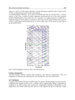
FIGURE 20.4: Lewiston-Queenston arch bridge, near Niagara Falls, New York, 1962. The world’s
longest fixed-arch span, at 1000 ft (305 m); rise is 159 ft (48 m). Box arch-rib sections are typically
about 3 × 13-1/2 ft (0.9 × 4.1 m) in cross-section and about 44-1/2 ft (13.6 m) long. Job was
estimated using erection tiebacks (same as shown in Figure 20.3), but subsequent studies showed the
long, sloping falsework bents to be more economical (even i f less secure looking). Much permanent
steelwork was used in the falsework bents. Derricks on approaches load steelwork onto material
cars that travel up arch ribs. The 115-ton-capacity travelers are shown erecting the last full-length
arch-rib sections, leaving only the short, closing crown sections to be erected. Canada is at left, the
U.S. at right. (Courtesy of Bethlehem Steel Corporation.)
and erection of steel bridges of all types. This theorem holds that the contractor’s best procedure for
achieving, in the completed structure, the deadload geometry and stressing stipulated on the design
plans, is generally as follows:
1. Determine deadload stress data for the structure, at its geometric outline and under
normal temperature, based on accurately calculated weights for all components.
2. Determine the cambered (i.e., “no-load”) dimensions of each component. This involves
determining the change of shape of each component from the deadload geometry, as
its deadload stressing is removed and its temperature is changed from normal to the
“shop-tape” temperature.
3. Fabricate, with all due precision, each structural component to its proper no-load dimen-
sions — except for certain flexible components such as wire rope and strand members,
which may require special t reatment.
4. Accomplish shop assembly of members and “reaming assembled” of holes in joints, as
needed.
5. Carry out comprehensive engineering studies of the structure under erection at each
key erection stage, determining corresponding stress and geometric data, and prepare a
step-by-step erection procedure plan, incorporating any check measurements that may
be necessary or desirable.
6. During the erection progr am, bring all members and joints to the designated alignment
prior to bolting or welding.
c
1999 by CRC Press LLC
FIGURE 20.5: Lewiston-Queenston arch bridge, near Niagara Falls, New York. Crawler cranes erect steelwork for spans 1 and 6 and erect material
derricks thereon. These derricks erect traveler derricks, which move forward and erect supporting falsework and spans 2, 5, and 4. Traveler
derricks erect arch-rib sections 1 and 2 and supporting falsework at each skewback, then set up creeper derricks, which erect arches to midspan.
c
1999 by CRC Press LLC
7. Enter and connect the final or closing structural components, following the closing pro-
cedure plan, without attempting any field measurements thereof or adjustments thereto.
In summary, the key to construction success is to accomplish the field surveys of critical baselines
and support elevations with all due precision, perform construction engineering studies compre-
hensively and shop fabrication accurately, and then carry the erection evolutions through in the field
without any second guessing and ill-advised attempts at measurement and adjustment.
It may be noted that no special treatment is accorded to statically indeterminate members; they are
fabricated and erected under the same governing considerations applicable to statically determinate
members, as set forth above. It may be noted further that this general steel bridge construction
philosophy does not rule out check measurements altogether, as erection goes forward; under certain
special conditions, measurements of stressing and/or geometry at critical erection stages may be
necessary or desirable in order to confirm structural integrity. However, before the erector calls for
any such measurements he should make certain that they will prove to be practical and meaning ful.
20.14 Example of Suspension Bridge Cable Construction
In order to illustrate the “shop control” construction philosophy further, its application to the main
cables of the first Wm. Preston Lane, Jr., Memorial Bridge, crossing the Chesapeake Bay in Maryland,
completed in 1952 (Figure 20.6), will be described. Suspension bridge cables constitute one of the
most difficult bridge erection challenges. Up until “first Chesapeake” the cables of major suspension
bridges had been adjusted to the correct position in each span by means of a sag survey of the
first-erected cable wires or strands, using surveying instruments and target rods. However, on first
Chesapeake, with its 1600-ft (488-m) main span, 661-ft (201-m) side spans, and 450-ft (l37-m)
back spans, the steelwork contractor recommended abandoning the standard cable-sag survey and
adopting the “setting-to-mark” procedure for positioning the guide strands — a significant new
concept in suspension bridge cable construction.
FIGURE 20.6: Suspension spans of first Chesapeake Bay Bridge, Maryland, 1952. Deck steelwork is
under erection and isabout 50% complete. A typical four-panel through-truss deck section, weighing
about 100 tons, is being picked in west side span, and also in east side span in distance. Main span
is 1600 ft (488 m) and side spans are 661 ft (201 m); towers are 324 ft (99 m) high. Cables are 14 in.
(356 mm) in diameter and are made up of 61 helical bridge strands each (see Figure 20.8).
The steelwork contractor’s rationale for “settingto marks” was spelled out in a letterto the designing
engineer (see Figure 20.7). (The complete letter is reproduced because it spells out significant
c
1999 by CRC Press LLC
construction philosophies.) This innovation was accepted by the designing engineer. It should be
noted that the contractor’s major argument was that setting to marks would lead to a more accurate
cable placement than would the sag survey. The minor arguments, alluded to in the letter, were the
resulting savings in preparatory office engineering work and in the field engineering effort, and most
likely in construction time as well.
Each cable consisted of 61 standard helical-type bridge strands, as shown in Figure 20.8.To
implement the setting-to-mark procedure each of three lower-layer “guide strands” of each cable
(i.e., strands 1, 2, and 3) was accurately measured in the manufacturing shop under the simulated
full-deadload tension, and circumferential marks were placed at the four center-of-saddle positions
of each strand. Then, in the field, the guide strands (each about 3955 ft [1205 m] long) were erected
and positioned according to the following procedure:
1. Place the three guide strands for each cable “on the mark” at each of the four saddles and
set normal shims at each of the two anchorages.
2. Under conditions of uniform temperature and no wind, measure the sag differences
among the three guide strands of each cable, at the center of each of the five spans.
3. Calculate the “center-of-gravity” position for each guide-str and group in each span.
4. Adjust the sag of each strand to bring it to the center-of-gravity position in each span.
This position was considered to represent the correct theoretical guide-strand sag in each
span.
The maximum“spread” from thehighestto theloweststrand at thespancenter, priorto adjustment,
was found to be 1-3/4 in. (44 mm) in the main span, 3-1/2 in. (89 mm) in the side spans, and 3-3/4
in. (95 mm) in the back spans. Further, the maximum change of perpendicular sag needed to bring
the guide strands to the center-of-gravity position in each span was found to be 15/16 in. (24 mm)
for the main span, 2-1/16 in. (52 mm) for the side spans, and 2-1/16 in. (52 mm) for the back
spans. These small adjustments testify to the accuracy of strand fabrication and to the validity of
the setting-to-mark strand adjustment procedure, which was declared to be a success by all parties
concerned. It seems doubtful that such accuracy in cable positioning could have been achieved using
the standard sag-survey procedure.
With the first-layer strands in proper position in each cable, the strands in the second and subse-
quent layers were positioned to hang correctly in relation to the first layer, as is customary and proper
for suspension bridge cable construction.
This example provides good illustration that the construction engineering philosophy referred
to as the shop-control procedure can be applied advantageously not only to typical rigid-type steel
structures, such as continuous trusses and arches, but also to flexible-typ e structures, such as sus-
pension bridges. There is, however, an important caveat: the steelwork contractor must be a firm of
suitable caliber and experience.
20.15 Example of Cable-Stayed Bridge Construction
In the case cable-stayed bridges, the first of which were built in the 1950s, it appears that the governing
construction engineering philosophy calls for field measurement and adjustment as the means for
control of stay-cable and deck-structure geometry and stressing. For example, we have seen specifi-
cations calling for the completed bridge to meet the following geometric and stress requirements:
1. The deck elevation at midspan shall be within 12 in. (305 mm) of theoretical.
2. The deck profile at each cable attachment point shall be within 2 in. (50 mm) of a parabola
passing through the actual (i.e., field-measured) midspan point.
c
1999 by CRC Press LLC
FIGURE 20.7: Setting cable guide strands to marks.
c
1999 by CRC Press LLC
FIGURE 20.7: (Continued) Setting cable guide strands to marks.
c
1999 by CRC Press LLC
FIGURE 20.8: Main cable of first Chesapeake Bay suspension bridge, Maryland. Each cable consists
of 61 helical-ty pe bridge strands, 55 of 1-11/16 in. (43 mm) and 6 of 29/32 in. (23 mm) diameter.
Strands 1, 2, and 3 were designated “guide strands” and were set to mark at each saddle and to normal
shims at anchorages.
3. Cable-stay tensions shall be within 5% of the “corrected theoretical” values.
Such specification requirements introduce a number of problems of interpretation, field measure-
ment, calculation, and field correction procedure, such as the following:
1. Interpretation:
• The specifications are silent with respect to transverse elevation differentials. There-
fore, two deck-profile control parabolas are presumably needed, one for each side
of the bridge.
2. Field measurement of actual deck profile:
• The temperature will be neither constant nor uniform throughout the structure
during the survey work.
• The survey procedure itself will introduce some inherent error.
3. Field measurement of cable-stay tensions:
• Hydraulic jacks, if used, are not likely to be accurate within 2%, perhaps even 5%;
further, the exact point of “lift off ” will be uncertain.
• Other procedures for measuring cable tension, such as vibration or strain gaging,
do not appear to define tensions within about 5%.
• All cable tensions cannot be measured simultaneously; an extended per iod will be
needed, during which conditions will vary and introduce additional errors.
c
1999 by CRC Press LLC
4. Calculation of “actual” bridge profile and cable tensions:
• Field-measured data must be transformed by calculation into “corrected actual”
bridge profiles and cable tensions, at normal temperature and without erection
loads.
• Actual dead weig hts of structural components can differ by perhaps 2% from nomi-
nal weights, while temporary erection loads probably cannot be known within about
5%.
• The actual temperatureofstructural components will be uncertain and not uniform.
• The mathematical model itself will introduce additional error.
5. “Target condition” of bridge:
• The “target condition” to be achieved by field adjustment will differ from the geo-
metric condition, because of the absence of the deck wearing surface and other such
components; it must therefore be calculated, introducing additional error.
6. Determining field corrections to be carried out by erector, to transform “corrected actual”
bridge into “target condition” bridge:
• The bridge structure is highly redundant, and changing any one cable tension will
send geometric and cable-tension changes throughout the structure. Thus, an
iterative correction procedure will be needed.
It seems likely that the total effect of all these practical factors could easily be sufficient to render
ineffective the contractor’s attempts to fine tune the geometry and stressing of the as-erected structure
in order to bring it into agreement with the calculated bridge target condition. Further, there can
be no assurance that the specifications requirements for the deck-profile geometry and cable-stay
tensions are even compatible; it seems likely that either the deck geometry or the cable tensions may
be achieved, but not both.
Specifications clauses of the type cited seem clearly to constitute unwarranted and unnecessary
field-adjustment requirements. Such clauses are typically set forth by bridge designers who have
great confidence in computer-generated calculations, but do not have a sufficient background in
and understanding of the practical factors associated with steel bridge construction. Experience has
shown that field procedures for major bridges developed unilaterally by design engineers should be
reviewed carefully to determine whether they are practical and desirable and will in fact achieve the
desired objectives.
In view of all these considerations, the question comes forward as to what design and construction
principles should be followed to ensure that the deadload geometry and stressing of steel cable-stayed
bridges will fall within acceptable limits. Consistent with the general construction-eng ineering pro-
cedures recommended for other types of bridges, we should abandon reliance on field measurements
followed by adjust ments of geometry and stressing, and instead place prime reliance on proper geo-
metric control of bridge components during fabrication, followed by accurate erection evolutions as
the work goes forward in the field.
Accordingly, the proper construction procedure for cable-stayed steel bridges can be summarized
as follows:
1. Determine the actual bridge baseline lengths and pier-top elevations to a high degree of
accuracy.
2. Fabricate the bridge towers, cables, and girders to a high degree of geometric precision.
3. Determine, in the fabricating shop, the final residual errors in critical fabricated dimen-
sions, including cable-stay lengths after socketing, and positionsof socket bearing surfaces
or pinholes.
c
1999 by CRC Press LLC
4. Determine “corrected theoretical” shims for each individual cable stay.
5. During erection, bring all tower and girder structural joints into shop-fabricated align-
ment, with fair holes, etc.
6. At the appropriate erection stages, install “corrected theoretical” shims for each cable stay.
7. With the structure in the all-steel-erected condition (or other appropriate designated
condition), check it over carefully to determine whether any significant geometric or
other discrepancies are in evidence. If there are none, declare conditions acceptable and
continue with erection.
This construction engineering philosophy can be summarized by stating that if the steelwork
fabrication and erection are properly engineered and carried out, the geometry and stressing of the
completed structure will fall w ithin acceptable limits; whereas, if the fabrication and erection are
not properly done, corrective measurements and adjustments attempted in the field are not likely to
improve the structure, or even to prove satisfactory. Accordingly, in constructing steel cable-stayed
bridges we should place full reliance on accurate shop fabrication and on controlled field erection,
just as is done on other types of steel bridges, rather than attempting to make measurements and
adjustments in the field to compensate for inadequate fabrication and erection.
20.16 Field Checking at Critical Erection Stages
As has been stated previously, the best governing procedure for steel bridge construction is generally
the shop control procedure, wherein full reliance is placed on accurate fabrication of the bridge
components as the basis for the integrity of the completed structure. However, this philosophy does
not rule out the desirability of certain checks in the field as erection goes forward, with the objective
of providing assurance that the work is on target and no significant errors have been introduced.
It would be impossible to catalog those cases during steel bridge construction where a field check
might be desirable; such cases will generally suggest themselves as the construction engineering
studies progress. We will only comment that these field-check cases, and the procedures to be used,
should be looked at carefully, and even skeptically, to make certain that the measurements will be
both desirable and practical, producing meaningful information that can be used to augment job
integrity.
20.17 Determination of Erection Strength Adequacy
Quite commonly, bridge member forces during the erection stages will be altogether different from
those that w ill prevail in the completed structure. At each critical erection stage the bridge members
must be reviewed for strength and stability, to ensure structural integrity as the work goes forward.
Such a construction engineering review is typically the responsibility of the steelwork erector, who
carries out thorough erection studies of the structure and calls for strengthening or stabilizing of
members as needed. The erector submits the studies and recommendations to the designing engineer
for review and comment, but normally the full responsibility for steelwork structural integrity during
erection rests with the erector.
In the U.S., bridgework design specifications commonly require that stresses in steel structures
under erection shall not exceed cer tain multiples of design allowable stresses. Although this type of
erection stress limitation is probably safe for most steel structures under ordinary conditions, it is
not necessarily adequate for the control of the erection stressing of large monumental-type bridges.
The key point to be understood here is that fundamentally, there is no logical fixed relationship
between design allowable stresses, which are based upon somewhat uncertain long-term service
c
1999 by CRC Press LLC
FIGURE 20.9: Cable-stayed orthotropic-steel-deck bridge over Mississippi River at Luling, La., 1982;
view looking northeast. The main span is 1222 ft (372 m); the A-frame towers are 350 ft (107 m)
high. A barge-mounted ringer derrick erected the main steelwork, using a 340-ft (104-m) boom
with a 120-ft (37-m) jib to erect tower components weighing up to 183 tons, and using a shorter
boom for deck components. Cable stays at the ends of projecting cross girders are permanent; others
are temporary erection stays. Girder section 16-west of north portion of bridge, erected a few days
previously, is projecting at left; companion girder section 16-east is on barge ready for erection (see
Figure 20.10).
loading requirements along with some degree of assumed st ructural deterioration, and stresses that
are safe and economical during the bridge erection stages, where loads and their locations are normally
well defined and the structural material is in new condition. Clearly, the basic premises of the two
situations are significantly different, and “factored design stresses” must therefore be considered
unreliable as a basis for evaluating erection safety.
There is yet a further problem with factored design stresses. Large tr uss-type bridges in various
erection stages may undergo deflections and distortions that are substantial compared with those
occurring under service conditions, thereby introducing apprehension regarding the effect of the
secondary bending stresses that result from joint rigidity.
Recognizing these basic considerations, the engineering department of a major U.S. steelwork
contractor went forward in the early 1970’s to develop a logical philosophy for erection strength
appraisal of large structural steel frameworks, with particular reference to long-span bridges, and
implemented this philosophy with a stress analysis procedure. The effort was successful and the
results were reported in a paper published by the American Society of Civil Engineers in 1977 [5].
This stress analysis procedure, designated the erection rating factor (ERF) procedure, is founded
directly upon basic structural principles, rather than on bridge-member design specifications, which
are essentially irrelevant to the problem of erection stressing.
c
1999 by CRC Press LLC
FIGURE 20.10: Luling Bridge deck steelwork erection, 1982; view looking nor theast (refer to Fig-
ure 20.9) The twin box girders are 14 ft (4.3 m) deep; the deck plate is 7/16 in. (11 mm) thick.
Girder section 16-east is being raised into position (lower right) and will be secured by large-pin
hinge bars prior to fairing-up of joint holes and permanent bolting. Temporary erection stays are
jumped forward as girder erection progresses.
It may b e noted that a significant inducement toward development of the ERF procedure was the
failure of the first Quebec cantilever bridge in 1907 (see Figures 20.11 and 20.12). It was quite obvious
that evaluation of the structural safety of the Quebec bridge at advanced cantilever erection stages,
such as that portrayed in Figure 20.11, by means of the factored desig n stress procedure, would inspire
no confidence and would not be justifiable.
The erection rating factor (ERF) procedure can be summarized as follows:
1. Assume either (a) pin-ended members (no secondary bending), (b) plane-frame action
(rigid truss joints, secondary bending in one plane), or (c) space-frame action (br acing-
member joints also rigid, secondary bending in two planes), as engineering judgment
dictates.
2. Determine, for each designated erection stage, the member primary forces (axial) and
secondary forces (bending) attributable to gravity loads and wind loads.
3. Compute the member stresses induced by the combined erection axial forces and bending
moments.
4. Compute the ERF for each member at three or five locations: at the middle of the member;
at each joint, inside the gusset plates (usually at the first row of bolts); and, where upset
member plates or gusset plates are used, at the stepped-down cross-section outside each
joint.
5. Determine the minimum computed ERF for each member and compare it with the
stipulated minimum value.
c
1999 by CRC Press LLC
FIGURE 20.11: First Quebec railway cantilever bridge, 23 August 1907. Cantilever erection of south
main span, 6 days before collapse. The tower traveler erected the anchor span (on falsework) and
then the cantilever arm; then erected the top-chord traveler, which is shown erecting suspended span
at end of cantile ver arm. The main span of 1800 ft (549 m) was the world’s longest of any type. The
sidespan bottom chords second from pier (arrow) failed in compression because latticing connecting
chord corner angles was deficient under secondary bending conditions.
6. Where the computed minimum ERF equals or exceeds the stipulated minimum value, the
member is considered satisfactory. Where it is less, the member may be inadequate; the
critical par t of it is reevaluated in greater detail and the ERF recalculated for further com-
parison with the stipulated minimum. (Initially calculated values can often be increased
significantly.)
7. When the computed minimum ERF remains less than the stipulated minimum, the
member must be strengthened as required.
Note that member forces attributable to wind are treated the same as those attributable to gravity
loads. The old concept of “increased allowable stresses” for wind is not considered to be valid
for erection conditions and is not used in the ERF procedure. Maximum acceptable /r and b/t
values are included in the criteria. ERFs for members subjected to secondary bending moments are
calculated using interaction equations.
20.18 Philosophy of the Erection Rating Factor
In order that the structural integrity or reliability of a steel framework can be maintained throughout
the erection program, the minimum probable (or “minimum characteristic”) strength value of each
member must necessarily be no less than the maximum probable (or “maximum characteristic”)
force value, under the most adverse erection condition. In other words, the following relationship is
c
1999 by CRC Press LLC
FIGURE 20.12: Wreckage of south anchor span of first Quebec railway cantilever bridge, 1907. View
looking north from south shore a few days after collapse of 29 August 1907, the worst disaster in the
history of bridge construction. About 20,000 tons of steelwork fell into the St. Lawrence River, and
75 workmen lost their lives.
required:
S − S ≥ F + F
(20.1)
where
S = computed or nominal strength value for the member
S = maximum probable member strength underrun from the computed or nominal value
F = computed or nominal force value for the member
F = maximum probable member force overrun from the computed or nominal value
Equation 20.1 states that in the event the actual strength of the structural member is less than
the nominal strength, S, by an amount S, while at same time the actual force in the member is
greater than the nominal force, F , by an amount F, the member strength w ill still be no less than
the member force, and so the member will not fail during erection. This equation provides a direct
appraisal of erection realities, in contrast to the allowable-stress approach based on factored design
stresses.
Proceeding now to rearrange the terms in Equation 20.1, we find that
S
1 −
S
S
≥ F
1 +
F
F
;
S
F
≥
1 +
F
F
1 −
S
S
(20.2)
c
1999 by CRC Press LLC
The ERF is now defined as
ERF ≡
S
F
(20.3)
that is, the nominal st rength value, S, of the member divided by its nominal force value, F . Thus,
for erection structural integrity or reliability to be maintained, it is necessary that
ERF ≥
1 +
F
F
1 −
S
S
(20.4)
20.19 Minimum Erection Rating Factors
In view of possible errors in (1) the assumed weight of permanent structural components, (2) the
assumed weight and positioning of erection equipment, and (3) the mathematical models assumed
for purposes of erection structural analysis, it is reasonable to assume that the actual member force
for a given erection condition may exceed the computed force value by as much as 10%; that is, it is
reasonable to take F /F as equal to 0.10.
For tension members, uncertainties in (1) the area of the cross-section, (2) the strength of the
material, and (3) the member workmanship, indicate that the actual member strength may be up
to 15% less than the computed value; that is, S/S can reasonably be taken as equal to 0.15. The
additional uncertainties associated with compression member strength suggest that S/S be taken as
0.25 for those members. Placing these values into Equation 20.4, we obtain the following minimum
ERFs:
Tension members: ERF
t,min
= (1 + 0.10)/(1 − 0.15)
= 1.294, say 1.30
Compression members: ERF
c,min
= (1 + 0.10)/(1 − 0.25)
= 1.467, say 1.45
The proper interpretation of these expressions is that if, for a given tension (compression) member,
the ERF is calculated as 1.30 (1.45)ormore, the member can be declared safe for the particular erection
condition. Note that higher, or lower, values of erection rating factors may be selected if conditions
warrant.
The minimum ERFs determined as indicated are based on experience and judgment, guided by
analysis and test results. They do not reflect any specific probabilities of failure and thus are not based
on the concept of an acceptable risk of failure, which might be considered the key to a totally rational
approach to structural safety. This possible shortcoming in the ERF procedure might be at least
partially overcome by evaluating the parameters F /F and S/S on a statistical basis; however,
this would involve a considerable effort, and it might not even produce significant results.
It is important to recognize that the ERF procedure for determining erection st rength adequacy is
based directly on fundamental strength and stability criteria, rather than being only indirectly related
to such criteria through the medium of a design specification. Thus, the procedure gives uniform
results for the erection r ating of framed structural members irrespective of the specification that was
used to design the members. Obviously, the end use of the completed structure is irrelevant to its
strength adequacy during the erection configurations, and therefore the design specification should
not be brought into the picture as the basis for erection appr aisal.
Experience with application of the ERF procedure to long-span truss bridges has shown that it
places the erection engineer in much better contact with the physical significance of the analysis than
can be obtained by using the factored design stress procedure. Further, the ERF procedure takes
account of secondary stresses, which have generally been neglected in erection stress analysis.
c
1999 by CRC Press LLC