Basic Theory of Plates and Elastic Stability - Part 19 doc
Bạn đang xem bản rút gọn của tài liệu. Xem và tải ngay bản đầy đủ của tài liệu tại đây (437.4 KB, 25 trang )
Elgaaly, M. “Plate and Box Girders”
Structural Engineering Handbook
Ed. Chen Wai-Fah
Boca Raton: CRC Press LLC, 1999
PlateandBoxGirders
MohamedElgaaly
DepartmentofCivil&
ArchitecturalEngineering,
DrexelUniversity,
Philadelphia,PA
19.1Introduction
19.2StabilityoftheCompressionFlange
VerticalBuckling
•
LateralBuckling
•
TorsionalBuckling
•
CompressionFlangeofaBoxGirder
19.3WebBucklingDuetoIn-PlaneBending
19.4NominalMomentStrength
19.5WebLongitudinalStiffenersforBendingDesign
19.6UltimateShearCapacityoftheWeb
19.7WebStiffenersforShearDesign
19.8Flexure-ShearInteraction
19.9SteelPlateShearWalls
19.10In-PlaneCompressiveEdgeLoading
19.11EccentricEdgeLoading
19.12Load-BearingStiffeners
19.13WebOpenings
19.14GirderswithCorrugatedWebs
19.15DefiningTerms
References
19.1 Introduction
Plateandboxgirdersareusedmostlyinbridgesandindustrialbuildings,wherelargeloadsand/or
longspansarefrequentlyencountered.Thehightorsionalstrengthofboxgirdersmakesthemideal
forgirderscurvedinplan.Recently,thinsteelplateshearwallshavebeeneffectivelyusedinbuildings.
Suchwallsbehaveasverticalplategirderswiththebuildingcolumnsasflangesandthefloorbeams
asintermediatestiffeners.Althoughtraditionallysimplysupportedplateandboxgirdersarebuilt
upto150ftspan,severalthree-spancontinuousgirderbridgeshavebeenbuiltintheU.S.withcenter
spansexceeding400ft.
InitssimplestformaplategirderismadeoftwoflangeplatesweldedtoawebplatetoformanI
section,andaboxgirderhastwoflangesandtwowebsforasingle-cellboxandmorethantwowebsin
multi-cellboxgirders(Figure19.1).Thedesignerhasthefreedominproportioningthecross-section
ofthegirdertoachievethemosteconomicaldesignandtakingadvantageofavailablehigh-strength
steels.Thelargerdimensionsofplateandboxgirdersresultintheuseofslenderwebsandflanges,
makingbucklingproblemsmorerelevantindesign.Bucklingofplatesthatareadequatelysupported
alongtheirboundariesisnotsynonymouswithfailure,andtheseplatesexhibitpost-bucklingstrength
thatcanbeseveraltimestheirbucklingstrength,dependingontheplateslenderness.Althoughplate
c
1999byCRCPressLLC
FIGURE 19.1: Plate and box girders.
buckling has not been the basis for design since the early 1960s, buckling strength is often required
to calculate the post-buckling strength.
The trend toward limit state format codes placed the emphasis on the development of new design
approaches based on the ultimate strength of plate and box girders and their components. The
post-buckling strength of plates subjected to shear is due to the diagonal tension field action. The
post-buckling strength of plates subjected to uniaxial compression is due to the change in the stress
distribution after buckling, higher nearthesupported edges. An effective width with auniform stress,
equal to the yield stress of the plate material, is used to calculate the post-buckling strength [40].
The flange in a box girder and the web in plate and box girders are often reinforced with stiffeners
to allow for the use of thin plates. The designer has to find a combination of plate thickness and
stiffener spacing that will optimize the weight and reduce the fabrication cost. The stiffeners in most
cases are designed to divide the plate panel into subpanels, which are assumed to be suppor ted along
the stiffener lines. Recently, the use of corrugated webs resulted in employing thin webs without
the need for stiffeners, thus reducing the fabrication cost and also improving the fatigue life of the
girders.
The web of a girder and load-bearing diaphragms can be subjected to in-plane compressive patch
loading. The ultimate capacity under this loading condition is controlled by web crippling, which
can occur prior to or after local yielding. The presence of openings in plates subjected to in-plane
loads is unavoidable in some cases, and the presence of openings affects the stability and ultimate
strength of plates.
19.2 Stability of the Compression Flange
The compression flange of a plate girder subjected to b ending usually fails in lateral buckling, local
torsional buckling, or yielding; ifthe web is slenderthe compressionflangecan failby vertical buckling
into the web (Figure 19.2).
c
1999 by CRC Press LLC
FIGURE 19.2: Compression flange modes of failure.
19.2.1 Vertical Buckling
The following limiting value for the web slenderness ratio to preclude this mode of failure [4] can be
used,
h/t
w
≤
0.68E/
F
yf
F
yf
+ F
r
A
w
/A
f
(19.1)
where h and t
w
are the web height and thickness, respectively; A
w
is the area of the web; A
f
is the
area of the flange; E is Young’s modulus of elasticity; F
yf
is the yield stress of the flange material;
and F
r
is the residual tension that must be overcome to achieve uniform yielding in compression.
This limiting value may be too conservative since vertical buckling of the compression flange into
the web occurs only after general yielding of the flange. This limiting value, however, can be helpful
to avoid fatigue cracking under repeated loading due to out-of-plane flexing, and it also facilitates
fabrication.
The American Institute of Steel Construction (AISC) specification [32] uses Equation 19.1 when
the spacing between the vertical stiffeners, a, is more than 1.5 times the web depth, h(a/h>1.5).
In such a case the specification recommends that
h/t
w
≤ 14,000/
F
yf
(F
yf
+ 16.5) (19.2)
where a minimum value of A
w
/A
f
=0.5 was assumed and the residual tension was taken to be 16.5
ksi. Furthermore, when a/h is less than or equal to 1.5, higher web slenderness is permitted, namely
h/t
w
≤ 2000/
F
yf
(19.3)
19.2.2 Lateral Buckling
When a flange is not adequately supported in the lateral direction, elastic lateral buckling can occur.
The compression flange, together with an effective area of the web equal to A
w
/6, can be treated as
a column and the buckling stress can be calculated from the Euler equation [2]:
F
cr
= π
2
E/(λ)
2
(19.4)
where λ is the slenderness ratio, which is equal to L
b
/r
T
;L
b
is the length of the unbraced segment of
the beam; and r
T
is the radiusofgyration of the compression flange plus one-third of the compression
portion of the web.
The AISC specification adopted Equation 19.4, rounding π
2
E to 286,000 and assuming thatelastic
buckling will occur when the slenderness ratio, λ, is greater than λ
r
(= 756/
F
yf
).
Furthermore, Equation 19.4 is based on uniform compression; in most cases the bending is not
uniform within thelength of theunbraced segment ofthe beam. Toaccount fornonuniform bending,
c
1999 by CRC Press LLC
Equation 19.4 should be multiplied by a coefficient, C
b
[25], where
C
b
= 12.5M
max
/(2.5M
max
+ 3M
A
+ 4M
B
+ 3M
C
) (19.5)
where
M
max
= absolute value of maximum moment in the unbraced beam segment
M
A
= absolute value of moment at quarter point of the unbraced beam segment
M
B
= absolute value of moment at centerline of the unbraced beam segment
M
C
= absolute value of moment at three-quarter point of the unbraced beam segment
When the slenderness ratio, λ, is less than or equal to λ
p
(= 300/
F
yf
), the flange will yield before
it buckles, and F
cr
= F
yf
. When the flange slenderness ratio, λ, is greater than λ
p
and smaller than
or equal to λ
r
, inelastic buckling will occur and a straight line equation must be adopted between
yielding (λ ≤ λ
p
) and elastic buckling (λ>λ
r
) to calculate the inelastic buckling stress, namely
F
cr
= C
b
F
yf
1 − 0.5(λ −λ
p
)/(λ
r
− λ
p
)
≤ F
yf
(19.6)
19.2.3 Torsional Buckling
If the outstanding width-to-thickness ratio of the flange is high, torsional buckling may occur. If one
neglects any restraint provided by the web to the flange rotation, then the flange can be treated as a
long plate, which is simply supported (hinged) at one edge and free at the other, subjected to uniaxial
compression in the longitudinal direction. The elastic buckling stress under these conditions can be
calculated from
F
cr
= k
c
π
2
E/12(1 −µ
2
)λ
2
(19.7)
where k
c
is a buckling coefficient equal to 0.425 for a long plate simply supported and free at its
longitudinal edges; λ is equal to b
f
/2t
f
;b
f
and t
f
are the flange width and thickness, respectively;
and E and µ are Young’s modulus of elasticity and the Poisson ratio, respectively.
The AISC specification adopted Equation 19.7, rounding π
2
E/12(1−µ
2
) to 26,200 and assuming
k
c
= 4
√
h/t
w
, where 0.35 ≤ k
c
≥ 0.763. Furthermore, to allow for nonuniform bending, the
buckling stress has to be multiplied by C
b
, given by Equation 19.5. Elastic torsional buckling of the
compression flange will occur if λ is greater than λ
r
(= 230/
F
yf
/k
c
). When λ is less than or equal
to λ
p
(= 65/
F
yf
), the flange will yield before it buckles, and F
cr
= F
yf
. When λ
p
<λ≤ λ
r
,
inelastic buckling will occur and Equation 19.6 shall be used.
19.2.4 Compression Flange of a Box Girder
Lateral-torsional buckling does not govern the design of the compression flange in a box girder.
Unstiffened flanges and flanges stiffened with longitudinal stiffeners can be treated as long plates
supported along their longitudinal edges and subjected to uniaxial compression. In the AASHTO
(American Association of State Highway and Transportation Officials ) specification [1], the nominal
flexural stress, F
n
, for the compression flange is calculated as follows:
If w/t ≤ 0.57
kE/F
yf
, then the flange will yield before it buckles, and
F
n
= F
yf
(19.8)
If w/t > 1.23
kE/F
yf
, then the flange will elastically buckle, and
F
n
= kπ
2
E/12(1 −µ
2
)(w/t)
2
or
F
n
= 26,200 k(t/w)
2
(19.9)
c
1999 by CRC Press LLC
If 0.57
kE/F
yf
<w/t≤ 1.23
kE/F
yf
, then the flange buckles inelastically, and
F
n
= 0.592F
yf
[1 + 0.687sin(cπ/2)] (19.10)
In Equations 19.8 to 19.10,
w = the spacing between the longitudinal stiffeners, or the flange width for unstiffened flanges
c =
1.23 − (w/t)
F
yf
/kE
/0.66
k =
8I
s
/wt
3
1/3
≤ 4.0, for n = 1
k =
14.3I
s
/wt
3
n
4
1/3
≤ 4.0, for n = 2, 3, 4, or 5
n = number of equally spaced longitudinal stiffeners
I
s
= the moment of inertia of the longitudinal stiffener about an axis parallel to the flange and
taken at the base of the stiffener
The nominal stress, F
n
, shall be reduced for hybrid girders to account for the nonlinear variation
of stresses caused by yielding of the lower strength steel in the web of a hybrid girder. Furthermore,
another reduction is made for slender webs to account for the nonlinear variation of stresses caused
by local bend buckling of the web. The reduction factors for hybrid girders and slender webs will
be g iven in Section 19.3. T he longitudinal stiffeners shall be equally spaced across the compression
flange width and shall satisfy the following requirements [1].
The projecting width, b
s
, of the stiffener shall satisfy:
b
s
≤ 0.48t
s
E/F
yc
(19.11)
where
t
s
= thickness of the stiffener
F
yc
= specified minimum yield strength of the compression flange
The moment of inertia, I
s
, of each stiffener about an axis parallel to the flange and taken at the
base of the stiffener shall satisfy:
I
s
≥ wt
3
(19.12)
where
= 0.125k
3
for n = 1
= 0.07k
3
n
4
for n = 2, 3, 4, or 5
n = number of equally spaced longitudinal compression flange stiffeners
w = larger of the width of compression flange between longitudinal stiffeners or the distance
from a web to the nearest longitudinal stiffener
t = compression flange thickness
k = buckling coefficient as defined in connection with Equations 19.8 to 19.10
The presence of the in-plane compression in the flange magnifies the deflection and stresses in the
flange from local bending due to traffic loading. The amplification factor, 1/(1 − σ
a
/σ
cr
), can be
used to increase the deflections and stresses due to local bending; where σ
a
and σ
cr
are the in-plane
compressive and buckling stresses, respectively.
19.3 Web Buckling Due to In-Plane Bending
Buckling of the web due to in-plane bending does not exhaust its capacity; however, the distribution
of the compressive bending stress changes in the post-buckling range and the web becomes less
efficient. Only part of the compression portion of the web can be assumed effective after buckling.
A reduction in the girder moment capacity to account for the web bend buckling can be used, and
the following reduction factor [4] has been suggested:
R = 1 −0.0005(A
w
/A
f
)(h/t − 5.7
E/F
yw
) (19.13)
c
1999 by CRC Press LLC
It must be noted that when h/t = 5.7
E/F
yw
, the web will yield before it buckles and there is
no reduction in the moment capacity. This can be determined by equating the bend buckling stress
to the web yield stress, i.e.,
kπ
2
E/
12(1 −µ
2
)(h/t )
2
= F
yw
(19.14)
where k is the web bend buckling coefficient, which is equal to 23.9 if the flange simply supports the
web and 39.6 if one assumes that the flange provides full fixity; the 5.7 in Equation 19.13 is based on
a k valueof36.
The AISC specification replaces the reduction factor given in Equation 19.13 by
R
PG
= 1 −
[
a
r
/(1,200 +300a
r
)
]
(h/t − 970/
F
cr
) (19.15)
where a
r
is equal to A
w
/A
f
and 970 is equal to 5.7
√
29000; it must be noted that the yield stress
in Equation 19.13 was replaced by the flange critical buckling stress, which can be equal to or less
than the yield stress as discussed earlier. It must also be noted that in homogeneous girders the yield
stresses of the web and flange materials are equal; in hybrid girders another reduction factor, R
e
,[39]
shall be used:
R
e
=
12 +a
r
(3m − m
3
)
/(12 +2a
r
) (19.16)
where a
r
is equal to the ratio of the web area to the compression flange area (≤ 10) and m is the ratio
of the web yield stress to the flange yield or buckling stress.
19.4 Nominal Moment Strength
The nominal moment strength can be calculated as follows.
Based on tension flange yielding:
M
n
= S
xt
R
e
F
yt
(19.17a)
or
Based on compression flange buckling:
M
n
= S
xc
R
PG
R
e
F
cr
(19.17b)
whereS
xc
and S
xt
arethe section modulireferred to thecompressionand tension flanges,respectively;
F
yt
is the tension flangeyield stress; F
cr
is the compression flange buckling stress calculated according
to Section 19.2; R
PG
is the reduction factor calculated using Equation 19.15; and R
e
isareduction
factor to be used in the case of hybrid girders and can be calculated using Equation 19.16.
19.5 Web Longitudinal Stiffeners for Bending Design
Longitudinal stiffeners can increase the bending strength of plate girders. This increase is due to
the control of the web lateral deflection, which increases its flexural stress capacity. The presence of
the stiffener also improves the bending resistance of the flange due to a greater web restraint. If one
longitudinal stiffener is used, its optimum location is 0.20 times the web depth from the compression
flange. In this case the web plate elastic bend buckling stress increases more than five times that
without the stiffener. Tests [8] showed that an adequately proportioned longitudinal stiffener at 0.2h
from the compression flange eliminates bend buckling in girders with web slenderness, h/t, as large
as 450. Girders with larger slenderness will require two or more longitudinal stiffeners to eliminate
c
1999 by CRC Press LLC
web bend buckling. It must be noted that the increase in the bending strength of a longitudinally
stiffened thin-web girder is usually small because the web contribution to the bending strength is
small. However, longitudinal stiffeners can be important in a girder subjected to repeated loads
because they reduce or eliminate the out-of-plane bending of the web, which increases resistance to
fatigue cracking at the web-to-flange juncture and allows more slender webs to be used [42].
The AISC specification does not address longitudinal stiffeners; on the other hand, the AASHTO
specification states that long itudinal stiffeners should consist of either a plate welded longitudinally
to one side of the web or a bolted angle, and shall be located at a distance of 0.4 D
c
from the inner
surface of the compression flange, where D
c
is the depth of the web in compression at the section with
the maximum compressive flexural stress. Continuous longitudinal stiffeners placed on the opposite
side of the web from the transverse intermediate stiffeners, as shown in Figure 19.3, are preferred.
If longitudinal and transverse stiffeners must be placed on the same side of the web, it is preferable
FIGURE 19.3: Longitudinal stiffener for flexure.
that the longitudinal stiffener not be interrupted for the transverse stiffener. Where the transverse
stiffeners are interrupted, the interruptions must be carefully detailed with respect to fatigue.
To prevent local buckling, the projecting width, b
s
of the stiffener shall satisfy the requirements of
Equation 19.11. The sectionproperties of the stiffenershall be based on an effective sectionconsisting
of the stiffener and a centrally located strip of the web not exceeding 18 times the web thickness.
The moment of inertia of the longitudinal stiffener and the effective web strip about the edge in
contact with the web, I
s
, and the corresponding radius of gyration, r
s
, shall satisfy the following
requirements:
I
s
≥ ht
3
w
2.4(a/ h)
2
− 0.13
(19.18)
and
r
s
≥ 0.234a
F
yc
/E (19.19)
where
a = spacing between transverse stiffeners
19.6 Ultimate Shear Capacity of the Web
As stated earlier, in mostdesign codes bucklingis not used as abasisfor design. Minimum slenderness
ratios, however, are specified to control out-of-plane deflection of the web. These ratios are derived
to give a small factor of safety against buckling, which is conservative and in some cases extravagant.
c
1999 by CRC Press LLC
Before the web reaches its theoretical buckling load the shear is taken by beam action and the
shear stress can be resolved into diagonal tension and compression. After buckling, the diagonal
compression ceases to increase and any additional loads will be carried by the diagonal tension. In
very thin webs with stiff boundaries, the plate buckling load is very small and can be ignored and the
shear is carried by a complete diagonal tension field action [41]. In welded plate and box girders the
web is not very slender and the flanges are not very stiff; in such a case the shear is carried by beam
action as well as incomplete tension field action.
Based on test results, the analytical modelshown in Figure19.4 can be usedtocalculate theultimate
shear capacity of the web of a welded plate girder [5]. The flanges are assumed to be too flexible to
FIGURE 19.4: Tension field model by Basler.
support the vertical component from the tension field. The inclination and width of the tension field
were defined by the angle , which is chosen to maximize the shear strength. The ultimate shear
capacity of the web, V
u
, can be calculated from
V
u
=
τ
cr
+ 0.5σ
yw
(1 − τ
cr
/τ
yw
) sin
d
A
w
(19.20)
where
τ
cr
= critical buckling stress in shear
τ
yw
= yield stress in shear
σ
yw
= web yield stress
d
= angle of panel diagonal with flange
A
w
= area of the web
In Equation 19.20,ifτ
cr
≥ 0.8τ
yw
, the buckling will be inelastic and
τ
cr
= τ
cri
=
0.8τ
cr
τ
yw
(19.21)
It was shown later [23] that Equation 19.20 gives the shear strength for a complete tension field
instead of the limited band shown in Figure 19.4. The results obtained from the formula, however,
were in good agreement with the test results, and the formula was adopted in the AISC specification.
Many variations of this incomplete tension field model have been developed; are view can be
found in the SSRC Guide to Stability Design Criteria for Metal Structures [22]. The model shown in
Figure 19.5 [36, 38] gives better results and has been adopted in codes in Europe. In the model shown
in Figure 19.5, near failure the tensile membrane stress, together with the buckling stress, causes
yielding , and failure occurs when hinges form in the flanges to produce a combined mechanism that
includes the yield zone ABCD. The vertical component of the tension field is added to the shear at
buckling and combined with the frame action shear to calculate the ultimate shear strength. The
c
1999 by CRC Press LLC
FIGURE 19.5: Tension field model by Rockey et al.
ultimate shear strength is determined by adding the shear at buckling, the vertical component of the
tension field, and the frame action shear, and is given by
V
u
= τ
cr
A
w
+ σ
t
A
w
[
(2c/h) +cot −cot
d
]
sin
2
+ 4M
p
/c (19.22)
where
σ
t
=−1.5τ
cr
sin 2 +
σ
2
yw
+ (2.25 sin
2
2 − 3)τ
2
cr
c = (2/ sin )
√
Mp/(σ
t
t
w
) 0 ≤ c ≤ a
M
p
= plastic moment capacity of the flange w ith an effective depth of the web, b
e
,givenby
b
e
= 30t
w
[1 − 2(τ
cr
/τ
yw
)]
where (τ
cr
/τ
yw
) ≤ 0.5; reduction in M
p
due to the effect of the flange axial compression shall be
considered and when τ
cr
> 0.8τ
yw
,
τ
cr
= τ
cri
= τ
yw
[1 − 0.16(τ
yw
/τ
cr
)]
The maximum value of V
u
must be found by trial; is the only independent variable in Equa-
tion 19.22, and the optimum is not difficult to determine by trial since it is between
d
/2 and 45
degrees, and V
u
is not sensitive to small changes from the optimum .
Recently [2, 33], it has been argued that the post-buckling strength arises not due to a diagonal
tension field action, but by redistribution of shear stresses and local yielding in shear along the
boundaries. A case in between is to model the web panel as a diagonal tension str ip anchored by
corner zones carrying shear stresses and act as gussets connecting the diagonal tension strip to the
vertical stiffeners which are in compression [9]. On the basis of test results, it can be concluded that
unstiffened webs possess a considerable reserve of post-buckling strength [16, 24]. The incomplete
diagonal tension field approach, however, is only reasonably accurate up to a maximum aspect ratio
(stiffeners spacing: web depth) equal to 6. Research is required to develop an appropriate method of
predicting the post-buckling strength of unstiffened girders.
In the AISC specification, the shear capacity of a plate girder web can be calculated, using the
model shown in Figure 19.4, as follows:
For h/t
w
≤ 187
k
v
/F
yw
, the web yields before buckling, and
V
n
= 0.6A
w
F
yw
(19.23)
c
1999 by CRC Press LLC
For h/t
w
> 187
k
v
/F
yw
, the web will buckle and a tension field will develop, and
V
n
= 0.6A
w
F
yw
C
v
+ (1 −C
v
)/1.15
1 + (a/h)
2
(19.24)
where
k
v
= buckling coefficient = 5 + 5/(a/h)
2
= 5,if(a/ h) > 3 or [260/(h/t
w
)]
2
C
v
= ratio of the web buckling stress to the shear yield stress of the web
= 187
k
v
/F
yw
/(h/t
w
), for 187
k
v
/F
yw
≤ h/tw ≤ 234
k
v
/F
yw
= 44,000 k
v
/[(h/t
w
)
2
F
yw
], for h/t
w
> 234
k
v
/F
yw
It must be noted that, in the above, the web buckling is elastic when h/t
w
> 234
k
v
/F
yw
.
The AISC specification does not permit the consideration of tension field action in end panels,
hybridand web-taperedplate girders,and whena/hexceeds3.0 or[260/(h/tw)]
2
. Thisiscontrary to
the fact that a tension field can develop in all these cases; however, little or no research was conducted.
Furthermore, tension field can be considered for end panels if the end stiffener is designed for this
purpose. When neglecting the tension field action, the nominal shear capacity can be calculated from
V
n
= 0.6A
w
F
yw
C
v
(19.25)
Care must be exercised in applying the tension field models developed primarily for welded plate
girders to the webs of a box girder. The thin flange of a box girder can provide very little or no
resistance against movements in the plane of the web. If the web of a box girder is transversely
stiffened and if the model show n in Figure 19.4 is used, it may overpredict the web strength. Hence,
it is advisable to use the model shown in Figure 19.5, assuming the plastic moment capacity of the
flange to be negligible.
19.7 Web Stiffeners for Shear Design
Transverse stiffeners must be stiff enough to prevent out-of-plane displacement along the panel
boundaries in computing shear buckling of plate girder webs. To provide the out-of-plane support
an equation, developed for an infinitely long web with simply supported edges and equally spaced
stiffeners, to calculate the required moment of inertia of the stiffeners, I
s
, namely for a ≤ h,
I
s
= 2.5ht
3
w
[(h/a) − 0.7(a/ h)] (19.26)
The AASHTO formula for load-factor design is
I
s
= Jat
3
w
(19.27)
where
J =[2.5(h/a)
2
− 2]≥0.5
Equation 19.27 is the same as Equation 19.26 except that the coefficient of (a/ h) in the second
term between brackets is 0.8 instead of 0.7. Equation 19.27 was adopted by the AISC specification as
well. The moment of inertia of the transverse stiffener shall be taken about the edge in contact with
the web for single-sided stiffeners and about the mid-thickness of the web for double-sided stiffeners.
To prevent local buckling of transverse stiffeners, the width, b
s
, of each projecting stiffener ele-
ment shall satisfy the requirements of Equation 19.11 using the yield stress of the stiffener material
rather than that of the flange, as in Equation 19.11. Furthermore, b
s
shall also satisfy the following
requirements:
16.0t
s
≥ b
s
≤ 0.25b
f
(19.28)
c
1999 by CRC Press LLC
where
b
f
= the full width of the flange
Transverse stiffeners shall consist of plates or angles welded or bolted to either one or both sides
of the web. Stiffeners that are not used as connection plates shall be a tight fit at the compression
flange, but need not be in bearing with the tension flange. The distance between the end of the web-
to-stiffener weld and the near edge of the web-to-flange fillet weld shall not be less than 4t
w
or more
than 6t
w
. Stiffeners used as connecting plates for diaphragms or cross-frames shall be connected by
welding or bolting to both flanges.
In girders with longitudinal stiffeners the transverse stiffener must also support the longitudinal
stiffener as it forces a horizontal node in the bend buckling configuration of the web. In such a case
it is recommended that the transverse stiffener section modulus, S
T
, be equal to S
L
(h/a),whereS
L
is the section modulus of the longitudinal stiffener and h and a are the web depth and the spacing
between the transverse stiffeners, respectively. In the AASHTO specification, the moment of inertia
of transverse stiffeners used in conjunction with longitudinal stiffeners shall also satisfy
I
t
≥ (b
t
/b
l
)(h/3a)I
l
(19.29)
where b
t
and b
l
=projecting width of t ransverse and longitudinal stiffeners, respectively, and I
t
and
I
l
= moment of inertia of t ransverse and longitudinal stiffeners, respectively.
Transverse stiffeners in girders that rely on a tension field must also be designed for their role in
the development of the diagonal tension. In this situation they are compression members, and so
must be checked for local buckling. Furthermore, they must have cross-sectional area adequate for
the axial force that develops. The axial force, F
s
, can be calculated based on the analytical model [5]
shown in Figure 19.4, and is given by
F
s
= 0.5F
yw
at
w
1 −
τ
cr
/τ
yw
(1 − cos
d
) (19.30)
The AISC and AASHTO specifications assume that a width of the web equal to 18t
w
acts with the
stiffener and give the following formula for the cross-sectional area, A
s
, of the stiffeners:
A
s
≥
0.15Bht
w
(1 − C
v
)V
u
/0.9V
n
− 18t
2
w
(F
yw
/F
ys
) (19.31)
where the new notations are
0.9V
u
= shear due to factored loads
B = 1.0 for double-sided stiffeners
= 1.8 for single-sided angle stiffeners
= 2.4 for single-sided plate stiffeners
If longitudinally stiffened girders are used, h in Equation 19.31 shall be taken as the depth of the
web, since the tension field will occur between the flanges and the transverse stiffeners.
The optimum locationof alongitudinal stiffenerthat is usedto increase resistance to shearbuckling
is at the web mid-depth. In this case the two subpanels buckle simultaneously and the increase in the
critical stress is substantial. To obtain the tension field shear resistance one can assume that only one
tension field is developed between the flanges and transverse stiffeners even if longitudinal stiffeners
are used.
19.8 Flexure-Shear Interaction
The shear capacity of a girder is independent of bending as long as the applied moment is less than the
moment that can be taken by the flanges alone, M
f
= σ
yf
A
f
h; any larger moment must be resisted
in part by the web, which reduces the shear capacity of the girder. When the girder is subjected to
c
1999 by CRC Press LLC
pure bending with no shear, the maximum moment capacity is equal to the plastic moment capacity,
M
p
, due to yielding of the girder’s entire cross-section. In view of the tension field action and based
on test results [3], a simple conservative interaction equation is given by
(V /V
u
)
2
+ (M − M
f
)/(M
p
− M
f
) = 1 (19.32)
where M and V are the applied moment and shear, respectively.
In the AISC specification, plate girders with webs designed for tension field action and when the
ultimate shear, V
u
, is between 0.54 and 0.9V
n
, and the ultimate moment, M
u
, is between 0.675 and
0.9M
n
,whereV
n
and M
n
are the nominal shear and moment capacities in absence of one another;
the following interaction equation must be satisfied,
M
u
/0.9M
n
+ 0.625(V
u
/0.9V
n
) ≤ 1.375 (19.33)
19.9 Steel Plate Shear Walls
Although the post-buckling behavior of plates under monotonic loads has been under investigation
for more than half a century, post-buckling strength of plates under cyclic loading has not been
investigated until recently [7]. The results of this investigation indicate that plates can be subjected
to few reversed cycles of loading in the post-buckling domain, without damage. In steel plate shear
walls, the boundary members are stiff and the plate is relatively thin; in such cases a complete tension
field can be developed. The plate can be modeled as a series of tension bars inclined at an angle,
φ [27]. The angle of inclination, φ, is a function of the panel length and height, the plate thickness,
the cross-sectional areas of the surrounding beams and columns, and the moment of inertia of the
columns. It can be determined by applying the principle of least work and is given by
tan
4
α =
[
(2/t
w
L) + (1/A
c
)
]
/
(2/t
w
L) + (2h/A
b
L) + (h
4
/180I
c
L
2
)
(19.34)
where
α = angle of inclination of tension field with the vertical axis
L = panel length
h = panel height
t
w
= wall thickness
A
b
= cross-sectional area of beam
A
c
= cross-sectional area of column
I
c
= moment of inertia of column about axis perpendicular to the plane of the wall
Although this model can predict the ultimate capacity to a reasonable degree of accuracy it cannot
depict the load-deflection characteristics to the same degree of accuracy. Based on test results and
finite element analysis [17, 18], the stresses in the inclined tensile plate strips are not uniform but
are higher near the supporting boundaries than the center of the plate, and yielding of these strips
starts near their ends and propagates toward the midlength. The following method can be used to
calculate the ultimate capacity and determine the load-deflection characteristics of a thin-steel-plate
shear wall.
The plate in the shear wall is replaced by a series of truss elements in the diagonal tension direction,
as shown in Figure 19.6. A minimum of four truss members shall b e used to replace the plate panel
in order to depict the panel behavior to a reasonable degree of accuracy; however, six members are
recommended. The stress-strain relationship for the truss elements shall be assumed to be bilinearly
elastic perfectly plastic, as shown in Figure 19.7,whereE is Young’s modulus of elasticity and σ
y
is the tensile yield stress of the plate material. In Figure 19.7 the first slope represents the elastic
c
1999 by CRC Press LLC
FIGURE 19.6: Steel plate shear wall analytical model.
FIGURE 19.7: Stress-strain relationship for truss element.
response and the second represents the reduced stiffness caused by partial yielding; σ
y1
and E
2
can
be determined using a semi-empirical approach for welded as well as bolted shear walls, and can be
calculated using the following equations:
σ
y1
= (0.423 +0.816b
e
/L)σ
y
(19.35)
where
b
e
=
14.6π
2
E/12(1 −ν
2
)τ
y
0.5
t (19.36)
L = length of the strip
t = thickness of the plate
and
E
2
=
(σ
y2
− σ
y1
)(3 − σ
y1
)/σ
y2
(2 +α)
E (19.37)
c
1999 by CRC Press LLC
where α is the ratio between the plastic strain, ε
p
, and the strain at the initiation of yielding, ε
y
. This
ratio is in the range of 5 to 20, depending on the stiffness of the columns relative to the thickness
of the plate; a value of 10 can be used in design. In the derivation of Equations 19.35 and 19.36
the inclination angle of the equivalent truss elements was assumed to be 45 degrees. The angle of
inclination is usually in the range of 38 to 43 degrees and the effect of this assumption on the overall
behavior of the wall is negligible.
In order to define the load displacement relationship of the truss elements in a bolted shear wall,
the parameters P
y1
,K
1
,P
y
, and K
2
shown in Figure 19.8 need to be calculated. For a bolted plate,
FIGURE 19.8: Load-displacement relationship for truss element.
the initial yielding can occur when the plate at the bolted connection starts slipping or when it locally
yields near the boundaries as in the welded plate. The load due to slippage is controlled by the friction
coefficient between the connected surfaces and the normal force applied by the bolts. In case the
bolts were pre-tensioned to 70% of their ultimate tensile strength, slip will occur at a load equal to
P
y1
= n(0.7µF
b
u
A
b
) (19.38)
where n is the number of bolts at one end of the truss element; F
b
u
and A
b
are the ultimate tensile
strength and cross-section area of the bolt, respectively; and µ is the friction coefficient between the
connected surfaces. The load that causes initial yielding at the ends of the strip is the same as for the
welded plate, and can be obtained from Equation 19.35 by multiplying the stress, σ
y1
, by the strip
cross-sectional area, A
p
.
The usable load is the smaller of the loads that causes slippage or initial yielding at the ends of the
strip. The initial stiffness of the equivalent truss element can be calculated as follows:
K
1
= EA
p
/L (19.39)
The ultimate load is controlled by the total yielding of the plate strip, tearing at the bolt holes,
or shearing of the bolts. The smallest failure load is the controlling ultimate capacity of the truss
element. The ultimate load due to the strip yielding along its entire length,
P
y
= σ
y
A
p
(19.40)
The bolted shear wall should be designed such that plate yielding controls.
c
1999 by CRC Press LLC
Tearing at the bolt holes will occur when the edge distance is small or the bolt spacing is large,
which should be avoided in design because it is a brittle failure. The tearing load, denoted as P
y
, can
be calculated using the following formula:
P
y
= 1.4nσ
u
(L
e
− D/2)t (19.41)
where n is the number of bolts at the end of the truss element, σ
u
is the ultimate tensile strength of the
plate material, L
e
is the distance from the edge of the plate to the centroid of the bolt hole, D is the
diameter of the bolt, and t is the thickness of the plate. Note that in the above formula the ultimate
strength of the plate material in shear was assumed to be 0.7, its ultimate strength in tension.
The shear failure of the bolts can occur if the shear strength of the bolts is small or the spacing
between them is large. In such case the ultimate capacity of the tr uss element, which is denoted as
P
y
, can be calculated from one of the following formulas:
P
y
= 0.45nF
b
u
A
b
(19.42a)
P
y
= 0.60nF
b
u
A
b
(19.42b)
where n is the number of bolts and F
b
u
and A
b
are the ultimate strength and the g ross cross-section
area of the bolts, respectively. Equation 19.42a is used if the shear plane is within the threaded par t
of the bolt and Equation 19.42b is used if the shear plane is not within the threaded part of the bolt.
The ultimate load of the truss element is the smallest value of the plate total yielding capacity, the
tearing capacity, and the bolt shearing capacity, i.e.,
P
y
= min(P
y
,P
y
,P
y
) (19.43)
As stated earlier, the plate yielding shall control and the designer must ensure that P
y
is the smallest
of the three values.
As can be seen in Figure 19.8, in order to define the stiffness, K
2
, the displacement of the truss
element when the load reaches the ultimate capacity, P
y
, needs to be determined. This ultimate
displacementincludes thestretchingof theelement aswell astheslippageand thebearingdeformation
of the plate and the bolts at the connections. The plate strip represented by the truss element is
stretched under load; the elongation includes both elastic and plastic deformations. As discussed
earlier, dueto the nonuniform strain distribution along the lengthof the strip, theplasticdeformation
will occur mostly near the ends. If one assumes that the strain distribution along the length of the
strip is a second-degree parabola, and using a plastic deformation factor a, the elongation of the
truss element due to the plate elastic and plastic deformations can be calculated using the following
equation:
def
= (σ
y
/3E)(2 +α)L (19.44)
The elongation of the tr uss element due to slippage can be approximated by two times the hole
clearance, taking into consideration the slippage at both ends of the element [26]. The local defor-
mation at the bolt holes includes the effects of shearing, bending, and bearing deformations of the
fastener as well as local deformation of the connected plates, and can be taken as 0.2 times the bolt
diameter [21]. Having defined the ultimate elongation of the truss element, its reduced stiffness after
slippage and/or initial yielding can be obtained using the following equation:
K
2
= (P
y
− P
y1
)/
0.125 +0.2D + σ
y
(α −1)L/(3E)
(19.45)
c
1999 by CRC Press LLC
19.10 In-Plane Compressive Edge Loading
Webs of plate and box girders and load-bearing diaphragms in box girders can be subjected to local
in-plane compressive loads. Vertical (transverse) stiffeners can be provided at the location of the load
to prevent web crippling; however, this is not always possible, such as in the case of a moving load,
and it involves higher cost. Failure of the web under this loading is always due to cr ippling [10], as
shown in Figure 19.9; in thin webs crippling occurs before yielding of the web and in stocky webs
after yielding. The formula in the AISC specification predicts the crippling load, P
cr
, to a reasonable
FIGURE 19.9: Deformed shape under in-plane edge loading (only half of the beam is shown).
degree of accuracy [37]; this formula is
P
cr
= 135t
2
w
1 + 3(N/d)
t
w
/t
f
1.5
F
yw
t
f
/t
w
0.5
(19.46)
The formula given by Equation 19.46 is applicable if the load is applied at a distance not less than
half the member’s depth from its end; if the load is at a distance less than half the member’s depth,
the following formulae shall be used [14]:
For N/d ≤ 0.2,P
cr
= 68t
2
w
1 + 3(N/d)
t
w
/t
f
1.5
F
yw
t
f
/t
w
0.5
(19.47a)
For N/d > 0.2,P
cr
= 68t
2
w
1 + (4N/d − 0.2)(t
w
/t
f
)
1.5
F
yw
t
f
/t
w
0.5
(19.47b)
In addition to web crippling, the AISC specification requires a web yielding check; furthermore,
when the relative lateral movement between the loaded compression flange and the tension flange is
not restrained at the point of load application, sidesway buckling must be checked.
c
1999 by CRC Press LLC
19.11 Eccentric Edge Loading
Eccentricities in loading w ith respect to the plane of the web are unavoidable, and it was found that
there is a reduction in the web capacity due to the presence of an eccentricit y [13, 14]; for example,
in one case, an eccentricity of 0.5 in. reduced the web ultimate capacity to about half its capacity
under in-plane load. Furthermore, it was found that the effect of the load eccentricity in reducing the
ultimate capacity decreases as the ratio of the flange-to-web thickness increases. A deformed beam
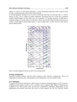
subjected to eccentric load near failure is shown in Figure 19.10. Web strength reduction factors for
various eccentricities as a function of the flange width and for various flange-to-web thickness ratios
are given in Figure 19.11.
FIGURE 19.10: Deformed shape under eccentric edge loading.
The failure mechanism in the case of eccentric loading is different from that for in-plane loading.
The flange twisting moment acting at the web-flange intersection can cause failure due to bending
rather than crippling of the web, if the eccentricity is large enough. In most cases, however, the failure
mode isdue to acombinationof webbending and crippling. Failure mechanisms were developed, and
formulas to calculate the ultimate capacity of the web under eccentric edge loading were derived [15].
Currently, the AISC specification does not address the effectof the eccentricity on the reduction of the
web crippling load. Eccentricities can also arise due to moments applied to the top flange in addition
to vertical loads. An example would be a beam resting on the top flange of another b eam and the
two flanges are welded together. Rotation of the suppor ted beam will impose a twisting moment in
the flange of the supporting beam and bending of its web, which will reduce its crippling load.
c
1999 by CRC Press LLC
FIGURE 19.11: Eccentricity reduction factor.
19.12 Load-Bearing Stiffeners
Webs of girders are often strengthened with transverse stiffeners at points of concentrated loads and
over intermediate and end supports. The AISC specification requires that these stiffeners be double
sided, extend at least one-half the beam depth, and either bear on or be welded to the loaded flange.
The specification, further, requires that they be designed as axially loaded members with an effective
length equals to 0.75 times the web depth; and a strip of the web, with a width equal to 25 times its
thickness for intermediate stiffeners and 12 times the thickness for end stiffeners, shall be considered
in calculating the geometric properties of the stiffener.
The failure, in cases where the stiffener depth is less than 75% of the depth of the web, can be due
to crippling of the web below the stiffener [14, 15], as shown in Figure 19.12. The failure, otherwise,
FIGURE 19.12: Web crippling below stiffener.
c
1999 by CRC Press LLC
is due to global buckling of the stiffener, provided that the thickness of the stiffener is adequate to
prevent local buckling. The optimum depth of the stiffener is 0.75 times the web depth. The AISC
specification does not account for factors such as the stiffener depth and load eccentricity.
Inboxgirdersintermediate diaphragms areprovided tolimit cross-sectionaldeformation andload-
bearing diaphragms are used at the supports to transfer loads to the bridge bearings. Diaphragm
design is treated in the BS 5400: Part 3 (1983) [6] and discussed in Chapter 7 of the SSRC guide [22].
19.13 Web Openings
Openings are frequently encountered in the webs of plate and box girders. Research on the buckling
and ultimate strength of plates with rectangular and circular openings subjected to in-plane loads
has been performed by many investigators. The research has included reinforced and unreinforced
openings. Atheoreticalmethod ofpredicting theultimatecapacityofslender webs containingcircular
and rectangular holes, and subjected to shear, has been developed [34, 35]. The solution is obtained
by considering the equilibrium of two tension bands, one above and the other below the opening.
These bands have been chosen to conform to the failure pattern observed in tested plate girders with
holes. Experimental results showed that the method gives satisfactory and safe predictions. The
calculated values were found to be between 5 and 30% below the test results.
Solutions for transversely stiffened webs subjected to shear and bending with centrally located
holes are available [28, 30] and are applicable for webs with depth-to-thickness ratios of 120 to 360,
panel aspect ratio between 0.7 and 1.5, hole depth greater than 1/10th of the web depth, and for
circular, elongated circular, and rectangular holes.
19.14 Girders with Corrugated Webs
Corrugated webs can be used in an effort to decrease the weight of steel girders and reduce its
fabrication cost. Studies have been conducted in Europe and Japan and girders with corrugated webs
have been used in these countries [12]. The results of the studies indicate that the fatigue strength
of girders with corrugated webs can be 50% higher compared to girders with flat stiffened webs. In
addition to the improved fatigue life, the weight of girders with corrugated webs can be as much as 30
to 60% less than the weight of girders with flat webs and have the same capacity. Due to the weight
savings, larger clear spans can be achieved. Beams and girders with corrugated webs are economical
to use and can improve the aesthetics of the structure. Beams manufactured and used in Ger many
for buildings have a web thickness that varies between 2 and 5 mm, and the corresponding web
height-to-thickness ratio is in the range of 150 to 260. The corrugated webs of two bridges built in
France were 8 mm thick and the web height-to-thickness ratio was in the range of 220 to 375.
Failure in shear is usually due to buckling of the web and the failure in bending is due to yielding of
the compression flange and its vertical buckling into the corrugated web, which buckles [19, 20]. The
shear buckling mode is global for dense corrugation and local for course corrugation, as shown in
Figure 19.13. The load-carrying capacity of the specimens drops after buckling, with some residual
load-carrying capacity after failure. In the local buckling mode, the corrugated web acts as a series
of flat-plate subpanels that mutually support each other along their vertical (longer) edges and are
supported by the flanges at their horizontal (shorter) edges. These flat-plate subpanels are subjected
to shear, and the elastic buckling stress is given by
τ
cre
= k
s
π
2
E/12(1 −µ
2
)(w/t)
2
(19.48)
c
1999 by CRC Press LLC
FIGURE 19.13: Local and global buckling .
where
k
s
= buckling coefficient, which is a function of the panel aspect ratio, h/w, and the boundary
support conditions
h = the web depth
t = the web thickness
w = the flat-plate subpanel width — the horizontal or the inclined, whichever is bigger
E = Young’s modulus of elasticity
µ = the Poisson ratio
The buckling coefficient, ks,isgivenby
k
s
= 5.34 +2.31(w/ h) −3.44(w/ h)
2
+8.39(w/ h)
3
, for the longer edges simply supported and
the shorter edges clamped
k
s
= 8.98 + 5.6(w/ h)
2
, in the case where all edges are clamped
An average local buckling stress, τ
av
(= 0.5[τ
ssf
+ τ
fx
]), is recommended, and in the case of
τ
cre
≥ 0.8τ
y
, inelastic buckling will occur and the inelastic buckling stress, τ
cri
, can be calculated by
τ
cri
= (0.8 ∗τ
cre
∗ τ
y
)
0.5
,whereτ
cri
≤ τ
y
.
As stated earlier, the mode of failure is local and/or global buckling; when global buckling controls,
the buckling stress can be calculated for the entire corrugated web panel, using orthotropic-plate
buckling theory. The global elastic buckling stress, τ
cre
, can be calculated from
τ
cre
= k
s
(
D
x
)
0.25
D
y
0.75
/th
2
(19.49)
where
D
x
= (q/s)Et
3
/12
D
y
= EI
y
/q
I
y
= 2bt(h
r
/2)
2
+{t(h
r
)
3
/6 sin }
k
s
= Buckling coefficient, equal to 31.6 for simply supported boundaries and 59.2 for clamped
boundaries
t = corrugated plate thickness
b, h
r
,q,s, and are as shown in Figure 19.14.
c
1999 by CRC Press LLC
In the aforementioned, when τ
cre
≥ 0.8τ
y
, inelastic buckling will occur and the inelastic buckling
stress, τ
cri
, can be calculated by τ
cri
= (0.8 ∗ τ
cre
∗ τ
y
)
0.5
,whereτcri ≤ τ
y
. For design, it is
recommended that the local and global buckling values be calculated and the smaller value controls.
As stated earlier, the failure in bending is due to compression flange yielding and vertical buckling
into the web, as show n in Figure 19.15. The failure is sudden, with no appreciable residual strength.
The web offers negligible contribution to the moment carrying capacity of the beam, and for design,
FIGURE 19.14: Dimensions of corrugation profile.
FIGURE 19.15: Bending failure of a beam with corrugate web.
the ultimate moment capacity can be calculated based on the flange yielding, ignoring any contribu-
tion from the web. The st resses in the web are equal to zero except near the flanges. This is because
the corrugated web has no stiffness perpendicular to the direction of the corrugation, except for a
c
1999 by CRC Press LLC
very small distance which is adjacent to and restrained by the flanges, and the stresses are appreciable
only within the horizontal folds of the corrugation.
It must be noted that the common practice is to fillet weld the web to the flanges from one side
only; under static loading this welding detail was found to be adequate and there is no need to weld
from both sides. Finally, the bracing requirements of the compression flange in beams and girders
with corrugated webs are less severe compared to conventional beams and girders with flat webs.
Lateral-torsional buckling of beams and girders with corrugated webs has been investigated [20].
19.15 Defining Terms
AASHTO: American Association of State Highway and Transpor tation Officials.
AISC: American Institute of Steel Construction.
Buckling load: The load at which a compressed element or member assumes a deflected posi-
tion.
Effective width: Reduced flat width of a plate element due to buckling, the reduced width is
termed the effective width.
Corrugated web: A web made of corrugated steel plates, where the corrugations are parallel to
the depth of the girder.
Factored load: The nominal load multiplied by a load factor to account for unavoidable devi-
ations of the actual load from the nominal load.
Limit state: A condition at which a structure or component becomes unsafe (strength limit
state) or no longer useful for its intended function (serviceability limit state).
LRFD (Load and Resistance Factor Design): A method of proportioning structural compo-
nents such that no applicable limit state is exceeded when the structure is subjected
to all appropriate load combinations.
Shear wall: A wall in a building to carry lateral loads from wind and earthquakes.
Stress: Force per unit area.
Web crippling: Local buckling of the web plate under local loads.
Web slenderness ratio: The depth-to-thickness ratio of the web.
References
[1] American Association of State Highway and Transportation Officials. 1994. AASHTO LRFD
Bridge Design Specifications, Washington, D.C.
[2] Ajam, W. and Marsh, C. 1991. Simple Model for Shear Capacity of Webs,
ASCE Struct. J.,
117(2).
[3] Basler, K. 1961. Strength of Plate Girders Under Combined Bending and Shear,
ASCE J. Struct.
Div.,
October, vol. 87.
[4] Basler K. and Th
¨
urlimann, B. 1963. Strength of Plate Girders in Bending,
Trans. ASCE, 128.
[5] Basler, K. 1963. Strength of Plate Girders in Shear,
Trans. ASCE, Vol. 128, Part II, 683.
[6] British StandardsInstitution. 1983.BS 5400: Part 3,Code ofPractice forDesign of SteelBridges,
BSI, London.
[7] Caccese, V., Elgaaly, M., and Chen, R. 1993. Experimental Study of Thin Steel-Plate Shear Walls
Under Cyclic Load,
ASCE J. Struct. Eng., February.
[8] Cooper, P.B. 1967. Strength of Longitudinally Stiffened Plate Girders,
ASCE J. Struct. Div.,
93(ST2), 419-452.
c
1999 by CRC Press LLC
[9] Dubas, P. and Gehrin, E. 1986. Behavior and Design of Steel Plated Structures, ECCS Publ. No.
44, TWG 8.3, 110-112.
[10] Elgaaly, M. 1983. Web Design Under Compressive Edge Loads,
AISC Eng. J., Fourth Quarter.
[11] Elgaaly, M. and Nunan W. 1989. Behavior of Rolled Sections Webs Under Eccentric Edge
Compressive Loads,
ASCE J. Struct. Eng., 115(7).
[12] Elgaaly, M. and Dagher, H. 1990. Beams and Girders with Corrugated Webs, Proceedings of
the SSRC Annual Technical Session, St. Louis, MO.
[13] Elgaaly, M. and Salkar, R. 1990. Behavior of Webs Under Eccentric Compressive Edge Loads,
Proceedings of IUTAM Symposium, Prague, Czechoslovakia.
[14] Elgaaly, M. and Salkar, R. 1991. Web Crippling Under Edge Loading, Proceedings of the AISC
National Steel Construction Conference, Washington, D.C.
[15] Elgaaly, M., Salkar, R., and Eash, M. 1992. Unstiffened and Stiffened Webs Under Compressive
Edge Loads, Proceedings of the SSRC Annual Technical Session, Pittsburgh, PA.
[16] Evans, H.R. and Mokhtari, A.R. 1992. Plate Girders with Unstiffened or Profiled Web Plates,
J.
Singapore Struct. Steel Soc.,
3(1), December.
[17] Elgaaly, M., Caccese, V., and Du, C. 1993. Postbuckling Behavior of Steel-Plate Shear Walls
Under Cyclic Loads,
ASCE J. Struct. Eng., 119(2).
[18] Elgaaly, M., Liu, Y., Caccese, V., Du, C., Chen, R., and Martin, D. 1994. Non-Linear Behav-
ior of Steel Plate Shear Walls,
Computational Structural Engineering for Practice, edited by
Papadrakakis and Topping, Civil-Comp Press, Edinburgh, UK.
[19] Elgaaly, M., Hamilton, R., and Seshadri, A. 1996. Shear Strength of Beams with Corrugated
Webs,
J. Struct. Eng., 122(4).
[20] Elgaaly, M., Seshadri, A., and Hamilton, R. 1996. Bending Strength of Beams with Corrugated
Webs,
J. Struct. Eng., 123(6).
[21] Fisher, J.W. 1965. Behavior of Fasteners and Plates with Holes,
J. Struct. Eng., ASCE, 91(6).
[22] Galambos, T.V., Ed. 1988.
Guide to Stability Design Criteria for Metal Structures, 4th ed.,
Wiley Interscience, New York.
[23] Gaylord, E.H. 1963. Discussion of K. Basler Strength of Plate Girders in Shear,
Trans. ASCE,
128, Part II, 712.
[24] Hoglund, T. 1971. Behavior and Load Carrying Capacity of Thin Plate I-Girders, Division of
Building Statics and Structural Engineering, Royal Institute of Technology, Bulletin No. 93,
Stockholm.
[25] Kirby, P.A. and Nethercat, D.A. 1979.
Design for Structural Stability, John Wiley & Sons, New
York .
[26] Kulak, G.L., Fisher, J.W., and Struik, J.H.A. 1987.
Guide to Design Criteria for Bolted and
Riveted Joints,
2nd ed., Wiley Interscience, New York.
[27] Kulak, G.L. 1985. Behavior of Steel Plate Shear Walls, Proc. of the AISC Int. Eng. Symp. on
Struct. Steel, American Institute of Steel Construction (AISC), Chicago, IL.
[28] Lee, M.M.K., Kamtekar, A.G., and Little, G.H. 1989. An Experimental Study of Perforated Steel
Web Plates,
Struct. Engineer, 67(2/24).
[29] Lee, M.M.K. 1990. Numerical Study of Plate Girder Webs with Holes,
Proc. Inst. Civ. Eng., Part
2.
[30] Lee, M.M.K. 1991. A Theoretical Model for Collapse of Plate Girders with Perforated Webs,
Struct. Eng., 68(4).
[31] Lindner, J. 1990. Lateral-Torsional Buckling of Beams with Trapezoidally Corrugated Webs,
Proceedings of the 4th International Colloquium on Stability of Steel Structures, Budapest,
Hungary.
[32] American Institute of Steel Construction. 1993.
Load and Resistance Factor Design Specifica-
tion for Structural Steel Buildings,
AISC, Chicago.
[33] Marsh, C. 1985. Photoelastic Study of Postbuckled Shear Webs,
Canadian J. Civ. Eng., 12(2).
c
1999 by CRC Press LLC
[34] Narayanan, R.and DerAvanessian, N.G.V. 1983.Strength ofWebs Containing Cut-Outs, IABSE
Proceedings P-64/83.
[35] Narayanan, R. and Der Avanessian, N.G.V. 1983. Equilibrium Solution for Predicting the
Strength of Webs with Rectangular Holes,
Proc. ICE, Part 2.
[36] Porter, D.M., Rockey, K.C., and Evans, H.R. 1975. The Collapse Behavior of Plate Girders
Loaded in Shear,
Struct. Eng., 53(8), 313-325.
[37] Roberts, T.M. 1981. Slender Plate Girders Subjected to Edge Loading,
Proc. Inst. Civil Eng.,
Part 2, 71.
[38] Rockey, K.C. and Skaloud, M. 1972. The Ultimate Load Behavior of Plate Girders Loaded in
Shear,
Struct. Eng., 50(1).
[39] Schilling, C.G. and Frost, R.W. 1964. Behavior of Hybrid Beams Subjected to Static Loads,
ASCE, J. Struct. D iv., 90(ST3), 55-88.
[40] Von Karman, T., Sechler, E.F., and Donnell, L.H. 1932. The Strength of Thin Plates in Com-
pression,
Trans. ASME, 54(2).
[41] Wagner, H. 1931. Flat Sheet Metal Girder with Very Thin Metal Web, NACA Te ch. Memo. Nos.
604, 605, 606.
[42] Yen, B.T. and Mueller, J.A. 1966. Fatigue Tests of Large-Size Welded Plate Girders,
Weld. Res.
Counc. Bull.,
No. 118, November.
c
1999 by CRC Press LLC