Basic Theory of Plates and Elastic Stability - Part 13 pps
Bạn đang xem bản rút gọn của tài liệu. Xem và tải ngay bản đầy đủ của tài liệu tại đây (417.78 KB, 59 trang )
Lan, T.T. “Space Frame Structures”
Structural Engineering Handbook
Ed. Chen Wai-Fah
Boca Raton: CRC Press LLC, 1999
Space Frame Structures
Tien T. Lan
Department of Civil Engineering,
Chinese Academy of
Building Research,
Beijing, China
13.1 Introduction to Space Frame Structures
General Introduction
•
Definition of the Space Frame
•
Basic
Concepts
•
Advantages of SpaceFrames
•
Preliminary Planning
Guidelines
13.2 Double Layer Grids
Types and Geometry
•
Type Choosing
•
Method of Support
•
Design Parameters
•
Cambering and Slope
•
Methods of
Erection
13.3 Latticed Shells
Form and Layer
•
Braced Barrel Vaults
•
Braced Domes
•
Hy-
perbolic Paraboloid Shells
•
Intersection and Combination
13.4 Structural Analysis
Design Loads
•
Static Analysis
•
Earthquake Resistance
•
Sta-
bility
13.5 Jointing Systems
General Description
•
Proprietary System
•
Bearing Joints
13.6 Defining Terms
References
Further Reading
13.1 Introduction to Space Frame Structures
13.1.1 General Introduction
A growing interest in space frame structures has been witnessed worldwide over the last half century.
The search for new structural forms to accommodate large unobstructed areas has always been
the main objective of architects and engineers. With the advent of new building techniques and
construction materials, space frames frequently provide the right answer and satisfy the requirements
for lightness, economy, and speedy construction. Significant progress has been made in the process
of the development of the space frame. A large amount of theoretical and experimental research
programs was carried out by many universities and research institutions in various countries. As a
result, a great deal of useful information has been disseminated and fruitful results have been put
into practice.
In the past few decades, the proliferation of the space frame was mainly due to its great structural
potential and visual beauty. New and imaginativeapplicationsof space frames arebeing demonstrated
in the total range of building types, such as sports arenas, exhibition pavilions, assembly halls,
transportation terminals, airplane hangars, workshops, and warehouses. They have been used not
only on long-span roofs, but also on mid- and short-span enclosures as roofs, floors, exterior walls,
c
1999 by CRC Press LLC
and canopies. Many interesting projects have been designed and constructed all over the world using
a variety of configurations.
Some important factors that influence the rapid development of the space frame can be cited
as follows. First, the search for large indoor space has always been the focus of human activities.
Consequently, sports tournaments, cultural performances, mass assemblies, and exhibitions can be
held under one roof. The modern production and the needs of greater operational efficiency also
created demand for large space with a minimum interference from internal supports. The space
frame provides the benefit that the interior space can be used in a variety of ways and thus is ideally
suited for such requirements.
Space frames are highly statically indeterminate and their analysis leads to extremely tedious
computation if by hand. The difficulty of the complicated analysis of such systems contributed to
their limited use. The introduction of electronic computers has radically changed the whole approach
to the analysis of space frames. By using computer programs, it is possible to analyze very complex
space structures with great accuracy and less time involved.
Lastly, the space frame also has the problem of connecting a large number of members (sometimes
up to 20) in space through different angles at a single point. The emergence of several connecting
methods of proprietary systems has made great improvement in the construction of the space frame,
which offered simple and efficient means for making connection of members. The exact tolerances
required by these jointing systems can be achieved in the fabrication of the members and joints.
13.1.2 Definition of the Space Frame
If one looks at technical literature on structural engineering, one will find that the meaning of the
space frame has been very diverse or even confusing. In a very broad sense, the definition of the space
frame is literally a three-dimensional structure. However, in a more restricted sense, space frame
means some type of special structure a ction in three dimensions. Sometimes structural engineers
and architects seem to fail to convey with it what they really want to communicate. Thus, it is
appropriate to define here the term space frame as understood throughout this section. It is best
to quote a definition given by a Working Group on Spatial Steel Structures of the International
Association [11].
A space frame is a structure system assembled of linear elements so ar ranged that
forces are transferred in a three-dimensional manner. In some cases, the constituent
element may be two-dimensional. Macroscopically a space frame often takes the form
of a flat or curved surface.
It should be noted that virtually the same structure defined as a space frame here is referred to as
latticed structures in a State-of-the-Art Report prepared by the ASCE Task Committee on Latticed
Structures [2] which states:
A latticed structure is a structure system in the form of a network of elements (as
opposed to a continuous surface). Rolled, extruded or fabricated sections comprise
the member elements. Another characteristic of latticed structural system is that their
load-carrying mechanism is three dimensional in nature.
The ASCE Report also specifies that the three-dimensional character includes flat surfaces with
loading perpendicular to the plane as well as curved surfaces. The Report excludes structural systems
such as common trusses or building frames, which can appropriately be divided into a series of planar
frameworks with loading in the plane of the framework. In this section the terms space frames and
latticed st ructures are considered synonymous.
c
1999 by CRC Press LLC
A space frame is usually arranged in an array of single, double, or multiple layers of intersecting
members. Some authors define space frames only as double layer grids. A single layer space frame
that has the form of a curved surface is termed as braced vault, braced dome,orlatticed shell.
Occasionally the term space truss appears in the technical literature. According to the structural
analysis approach, a space frame is analyzed by assuming rigid joints that cause internal torsions
and moments in the members, whereas a space truss is assumed as hinged joints and therefore has
no internal member moments. The choice between space frame and space truss action is mainly
determined by the joint-connection detailing and the member geometry is no different for both.
However, in engineering practice, there is no absolutely rigid or hinged joints. For example, a double
layer flat surface space frame is usually analyzed as hinged connections, while a single layer curved
surface space frame may be analyzed either as hinged or rigid connections. The term space frame will
be used to refer to both space frames and space trusses.
13.1.3 Basic Concepts
The space frame can be formed either in a flat or a curved surface. The earliest form of space frame
structures is a single layer g rid. By adding intermediate grids and including rigid connecting to the
joist and girder framing system, the single layer grid is formed. The major characteristic of grid
construction is the omni-directional spreading of the load as opposed to the linear transfer of the
load in an ordinar y framing system. Since such load transfer is mainly by bending, for larger spans,
the bending stiffness is increased most efficiently by going to a double layer system. The load transfer
mechanism of curved surface space frame is essentially different from the grid system that is primarily
membrane-like action. The concept of a space frame can be best explained by the following example.
EXAMPLE 13.1:
It is necessary to design a roof structure for a square building. Figure 13.1a and b show two
different ways of roof framing. The roof system shown in Figure 13.1a is a complex roof comprised
of planar latticed trusses. Each truss will resist the load acting on it independently and transfer the
load to the columns on each end. To ensure the integrity of the roof system, usually purlins and
bracings are used between trusses. In Figure 13.1b, latticed trusses are laid orthogonally to form a
system of space latticed grids that will resist the roof load through its integrated action as a whole and
transfer the loads to the columns along the perimeters.Since the loads can be taken by the members in
three dimensions, the corresponding forces in space latticed grids are usually less than that in planar
trusses, and hence the depth can be decreased in a space frame.
The same concept can be observed in the design of a circular dome. Again, there are two different
ways of framing a dome. The dome shown in Figure 13.2a is a complex dome comprised of elements
such as arches, primary and secondary beams, and purlins, which all lie in a plane. Each of these
elements constitutes a system that is stable by itself. In contrast, the dome shown in Figure 13.2bis
an assembly of a series of longitudinal, meridional, and diagonal members, which is a certain form
of latticed shell. It is a system whose resisting capacity is ensured only through its integral action as
a whole.
The difference between planar structures and space frames can be understood also by examining
the sequence of flow of forces. In a planar system, the force due to the roof load is transferred
successively through the secondary elements, the primary elements, and then finally the foundation.
In each case, loads are transferred from the elements of a lighter class to the elements of a heavier
class. As the sequence proceeds, the magnitude of the load to be transferred increases, as does the
span of the element. Thus, elements in a planar structure are characterized by their distinctive ranks,
not only judging by the size of their cross-sections, but also by the importance of the task assigned
c
1999 by CRC Press LLC
FIGURE 13.1: Roof framing for a square plan.
to them. In contrast, in a space frame system, there is no sequence of load transfer and all elements
contribute to the task of resisting the roof load in accordance with the three-dimensional geometry
of the structure. For this reason, the ranking of the constituent elements similar to planar structures
is not observed in a space frame.
13.1.4 Advantages of Space Frames
1. One of the most important advantages of a space frame structure is its light weight. It is
mainly due to fact that material is distributed spatially in such a way that the load transfer
mechanism is primarily axial—tension or compression. Consequently, all material in
any given element is utilized to its full extent. Furthermore, most space frames are now
constructed with steel or aluminum, which decreases considerably their self-weight. This
is especially important in the case of long span roofs that led to a number of notable
examples of applications.
2. The units of space frames are usually mass produced in the factory so that they can take
full advantage of an industrialized system of construction. Space frames can be built from
simple prefabricated units, which are often of standard size and shape. Such units can
be easily transported and rapidly assembled on site by semi-skilled labor. Consequently,
space frames can be built at a lower cost.
3. A space frame is usually sufficiently stiff in spite of its lightness. This is due to its three-
dimensional character and to the full participation of its constituent elements. Engineers
appreciate the inherent rigidity and great stiffness of space frames and their exceptional
ability to resist unsymmetrical or heavy concentrated load. Possessing greater rig idity,
c
1999 by CRC Press LLC
FIGURE 13.2: Roof framing for a circular dome.
the space frames also allow greater flexibility in layout and positioning of columns.
4. Space frames possess a versatility of shape and form and can utilize a standard module
to generate various flat space grids, latticed shell, or even free-form shapes. Architects
appreciate the visual beauty and the impressive simplicity of lines in space frames. A
trend is very noticeable in which the structural members are left exposed as a part of the
architectural expression. Desire for openness for both visual impact as well as the ability
to accommodate variable space requirements always calls for space frames as the most
favorable solution.
13.1.5 Preliminary Planning Guidelines
In the preliminary stage of planning a space frame to cover a specific building , a number of factors
should be studied and evaluated before proceeding to structural analysis and design. These include
not only structural adequacy and functional requirements, but also the aesthetic effect desired.
1. In its initial phase, structural design consists of choosing the general form of the building
and the type of space frame appropriate to this form. Since a space frame is assem-
bled from straight, linear elements connected at nodes, the geometrical arrangement of
the elements—surface shape, number of layers, grid pattern, etc.—needs to be studied
carefully in the light of various pertinent requirements.
2. The geometry of the space frame is an important factor to be planned which will influence
both the bearing capacity and weig ht of the structure. The module size is developed from
the overall building dimensions, while the depth of the grid (in case of a double layer),
the size of cladding, and the position of supports will also have a pronounced effect upon
it. For a curved surface, the geometry is also related to the curvature or, more specifically,
to the rise of the span. A compromise between these various aspects usually has to be
made to achieve a satisfactory solution.
c
1999 by CRC Press LLC
3. In a space frame, connecting joints play an important role, both functional and aesthetic,
which is derived from their rationality during construction and after completion. Since
joints have a decisive effect on the strength and stiffness of the structure and compose
around 20 to 30% of the total weight, joint design is critical to space frame economy and
safety. There are a number of proprietary systems that are used for space frame structures.
A system should be selected on the basis of quality, cost, and erection efficiency. In
addition, custom-designed space frames have been developed, especially for long span
roofs. Regardless of the type of space frame, the essence of any system is the jointing
system.
4. At the preliminary stage of design, choosing the type of space frame has to be closely
related to the constructional technology. The space frames do not have such sequential
order of erection for planar structures and require special consideration on the method
of construction. Usually a complete falsework has to be provided so that the structure
can be assembled in the high place. Alternatively, the structure can be assembled on the
ground, and certain techniques can be adopted to lift the whole structure, or its large
part, to the final position.
13.2 Double Layer Grids
13.2.1 Types and Geometry
Double layergrids, or flat surface space frames, consistof two planar networks of members forming the
top and bottom layers parallel to each other and interconnected by vertical and inclined web members.
Double layer grids are characterized by the hinged joints with no moment or torsional resistance;
therefore, all members can only resist tension or compression. Even in the case of connection by
comparatively rigid joints, the influence of bending or torsional moment is insignificant.
Double layer g rids are usually composed of basic elements such as:
• a planar latticed truss
• a pyramid with a square base that is essentially a part of an octahedron
• a pyramid with a triangular base (tetrahedron)
These basic elements used for various types of double-layer grids are shown in in Figure 13.3.
FIGURE 13.3: Basic elements of double layer grids.
c
1999 by CRC Press LLC
A large number of ty pes of double layer grids can be formed by these basic elements. They are
developed by varying the direction of the top and bottom layers with respect to each other and also by
the positioning of the top layer nodal points with respect to the bottom layer nodal points. Additional
variations can be introduced by chang ing the size of the top layer grid with respect to the bottom
layer grid. Thus, internal openings can be formed by omitting every second element in a normal
configuration. According to the form of basic elements, double layer grids can be divided in two
groups, i.e., latticed grids and space g rids. The latticed grids consist of intersecting vertical latticed
trusses and form a regular grid. Two parallel grids are similar in design, with one layer directly over
the top of another. Both top and bottom grids are directionally the same. The space grids consist of
a combination of square or triangular pyramids. This group covers the so-called offset grids, which
consist of parallel grids having an identical layout with one grid offset from the other in plane but
remaining directionally the same, as well as the so-called differential grids in which two parallel top
and bottom grids are of a different layout but are chosen to coordinate and form a regular pattern [20].
The type of double layer grid can be chosen from the following most commonly used framing
systems that are shown in Figure 13.4a through j. In Figure 13.4, top chord members are depicted
with heavy solid lines, bottom chords are depicted with light solid lines and web members with
dashed lines, while the upper joints are depicted by hollow circles and bottom joints by solid circles.
Different types of double layer grids are g rouped and named according to their composition and the
names in the parenthesis indicate those suggested by other authors.
Group 1. Composed of latticed trusses
1. Two-way orthogonal latticed grids (square on square) (Figure 13.4a). This type of latticed
grid has the advantage of simplicity in configuration and joint detail. All chord members
are of the same length and lie in two planes that intersect at 90
◦
to each other. Because of its
weak torsional strength, horizontal bracings are usually established along the perimeters.
2. Two-way diagonal latticed grids (Figure 13.4b). The layout of the latticed grids is exactly
the same as Type 1 except it is offset by 45
◦
from the edges. The latticed trusses have
different spans along two directions at each intersecting joint. Since the depth is all the
same, the stiffness of each latticed truss varies according to its span. The latticed trusses
of shorter spans may be considered as a certain kind of support for latticed trusses of
longer span, hence more spatial action is obtained.
3. Three-way latticed grids (Figure 13.4c). All chord members intersect at 60
◦
to each other
and form equilateral triangular grids. It is a stiff and efficient system that is adaptable to
those odd shapes such as circular and hexagonal plans. The joint detail is complicated by
numerous members intersecting at one point, with 13 members in an extreme case.
4. One-way latticed grids (Figure 13.4d). It is composed of a series of mutually inclined
latticed trusses to form a folded shape. There are only chord members along the spanning
direction; therefore, one-way action is predominant. Like Type 1, horizontal bracings are
necessary along the perimeters to increase the integral stiffness.
Group 2A. Composed of square pyramids
5. Orthogonal square pyramid space grids (square on square offset) (Figure 13.4e). This
is one of the most commonly used framing patterns with top layer square grids offset
over bottom layer grids. In addition to the equal length of both top and bottom chord
members, if the angle between the diagonal and chord members is 45
◦
, then all members
in the space grids will have the same length. The basic element is a square pyramid that
is used in some proprietary systems as prefabricated units to form this type of space grid.
6. Orthogonal square pyramid space grids with openings (square on square offset with
internal openings, square on larger square) (Figure 13.4f). The framing pattern is similar
c
1999 by CRC Press LLC
to Type 5 except the inner square pyramids are removed alternatively to form larger grids
in the bottom layer. Such modification will reduce the total number of members and
consequently the weight. It is also visually affective as the extra openness of the space
grids network produces an impressive architectural effect. Skylights can be used with this
system.
7. Differential square pyramid space grids (square on diagonal) (Figure 13.4g). This is a
typical example of differential grids. The two planes of the space grids are at 45
◦
to
each other which will increase the torsional stiffness effectively. The grids are arranged
orthogonally in the top layer and diagonally in the bottom layer. It is one of the most
efficient framing systems with shorter top chord members to resist compression and
longer bottom chords to resist tension. Even with the removal of a large number of
members, the system is still structurally stable and aesthetically pleasing.
8. Diagonal square pyramid space grids (diagonal square on square with internal openings,
diagonal on square) (Figure 13.4h). This type of space grid is also of the differential
layout, but with a reverse pattern from Type 7. It is composed with square pyramids
connected at their apices with fewer members intersecting at the node. The joint detail
is relatively simple because there are only six members connecting at the top chord joint
and eight members at the bottom chord joint.
Group 2B. Composed of triangular pyramids
9. Triangular pyramid space grids (triangle on triangle offset) (Figure 13.4i). Triangular
pyramids are used as basic elements and are connected at their apices, thus forming a
pattern of top layer triangular grids offset over bottom layer grids. If the depth of the
space grids is equal to
√
2/3 chord length, then all members will have the same length.
10. Triangular pyramid space grids with openings (triangle on triangle offset with internal
openings) (Figure 13.4j). Like Type 6, the inner triangular pyramids may also be removed
alternatively. As the figure shown, triangular grids are formed in the top layer while
triangular and hexagonal grids are formed in the bottom layer. The pattern in the bottom
layer may be varied depending on the ways of removal. Such types of space grids have a
good open feeling and the contrast of the patterns is effective.
13.2.2 Type Choosing
In the preliminary stage of design, it is most important to choose an appropriate type of double
layer grid that will have direct influence on the overall cost and speed of construction. It should
be determined comprehensively by considering the shape of the building plan, the size of the span,
supporting conditions, magnitude of loading, roof construction, and architectural requirements. In
general, the system should be chosen so that the space grid is built of relatively long tension members
and short compression members.
In choosing the type, the steel weight is one of the important factors for comparison. If possible,
the cost of the structure should also be taken into account, which is complicated by the different
costs of joints and members. By comparing the steel consumption of various types of double layer
grids with rectangular plans and supported along perimeters, it was found that the aspect ratio of the
plan, defined here as the ratio of a longer span to a shorter span, has more influence than the span of
the double layer grids. When the plan is square or nearly square (aspect ratio = 1 to 1.5), two-way
latticed grids and all space grids of Group 2A, i.e., Type 1, 2, and 5 through 8, could be chosen. Of
these types, the diagonal square pyramid space grids or differential square pyramid space grids have
the minimum steel weight. When the plan is comparatively narrow (aspect ratio = 1.5 to 2), then
those double layer grids with orthogonal gird systems in the top layer will consume less steel than
c
1999 by CRC Press LLC
FIGURE 13.4: Framing system of double layer grids.
c
1999 by CRC Press LLC
FIGURE 13.4: (Continued) Framing system of double layer grids.
c
1999 by CRC Press LLC
FIGURE 13.4: (Continued) Framing system of double layer grids.
those with a diagonal grid system. Therefore, two-way orthogonal latticed grids, orthogonal square
pyramid space grids, and also those with openings and differential square pyramid space grids, i.e.,
Types 1, 5, 6, and 7, could be chosen. When the plan is long and narrow, the type of one-way latticed
grid is the only selection. For square or rectangular double layer grids supported along perimeters
on three sides and free on the other side, the selection of the appropriate types for different cases is
essentially the same. The boundary along the free side should be strengthened either by increasing
the depth or number of layers. Individual supporting structures such as trusses or girders along the
free side are not necessary.
In case the double layer grids are supported on intermediate columns, type could be chosen
from two-way orthogonal latticed grids, orthogonal square pyramid space grids, and also those with
openings, i.e., Types 1, 5, and 6. If the supports for multi-span double layer grids are combined with
those along perimeters, then two-way diagonal latticed grids and diagonal square pyramid space
grids, i.e., Types 2 and 8, could also be used.
For double layer grids with circular, triangular, hexagonal, and other odd shapes supporting along
perimeters, types with triangular grids in the top layer, i.e., Types 3, 9, and 10, are appropriate for
use.
The recommended types of double layer grids are summarized in Table 13.1 according to the shape
of the plan and their supporting conditions.
c
1999 by CRC Press LLC
TABLE 13.1 Type Choosing for Double Layer Grids
Recommended
Shape of the plan Supporting condition types
Square, rectangular (aspect ratio = 1 to 1.5) Along perimeters 1, 2, 5, 6, 7, 8
Rectangular (aspect ratio
= 1.5 to 2) Along perimeters 1, 5, 6, 7
Long strip (aspect ratio
> 2) Along perimeters 4
Square, rectangular Intermediate support 1, 5, 6
Square, rectangular Intermediate support combined with support
along perimeters
1, 2, 5, 6, 8
Circular, triangular, hexagonal, and other odd
shapes
Along perimeters 3, 9, 10
13.2.3 Method of Support
Ideal double layer grids would be square, circular, or other polygonal shapes with overhanging and
continuous supports along the perimeters. This will approach more of a plate type of design which
minimizes the maximum bending moment. However, the configuration of the building has a great
number of varieties and the support of the double layer grids can take the following locations:
1. Support along perimeters—This is the most commonly used support location. The sup-
ports of double layer grids may directly rest on the columns or on ring beams connecting
the columns or exterior walls. Care should be taken that the module size of grids matches
the column spacing.
2. Multi-column supports—For single-span buildings, such as a sports hall, double layer
grids can be supported on four intermediate columns as shown in Figure 13.5a. For
buildings such as workshops, usually multi-span columns in the form of grids as shown
in Figure 13.5b are used. Sometimes the column grids are used in combination with
supports along perimeters as shown in Figure 13.5c. Overhangs should be employed
where possible in order to provide some amount of stress reversal to reduce the interior
chord forces and deflections. For those double layer grids supported on intermediate
columns, it is best to design with overhangs, which are taken as 1/4 to 1/3 of the mid-
span. Corner supports should be avoided if possible because they cause large forces in the
edge chords. If only four supports are to be provided, then it is more desirable to locate
them in the middle of the sides rather than at the corners of the building.
3. Support along perimeters on three sides and free on the other side—For buildings of a
rectangular shape, it is necessary to have one side open, such as in the case of an airplane
hanger or for future extension. Instead of establishing the supporting girder or truss on
the free side, triple layer grids can be formed by simply adding another layer of several
module widths (Figure 13.6). For shorter spans, it can also be solved by increasing the
depth of the double layer grids. The sectional area of the members along the free side will
increase accordingly.
The columns for double layer grids must support gravity loads and possible lateral forces. Typical
types of support on multi-columns are shown in Figure 13.7. Usually the member forces around the
support will be excessively large, and some means of transferring the loads to columns are necessary. It
may carry the space grids down to the column top by an inverted pyramid as shown in Figure 13.7aor
by triple layer grids as shown in Figure 13.7b, which can be employed to carry skylights. If necessary,
the inverted pyramids may be extended down to the ground level as shown in Figure 13.7c. The
spreading out of the concentrated column reaction on the space grids reduces the maximum chord
and web member forces adjacent to the column supports and reduces the effective spans. The use
of a vertical strut on column tops as shown in Figure 13.7d enables the space grids to be suppor ted
on top chords, but the vertical strut and the connecting joint have to be very strong. The use of
c
1999 by CRC Press LLC
FIGURE 13.5: Multi-column supports.
FIGURE 13.6: Triple layer grids on the free side.
crosshead beams on column tops as shown in Figure 13.7e produces the same effect as the inverted
pyramid, but usually costs more in material and special fabrication.
FIGURE 13.7: Supporting columns.
c
1999 by CRC Press LLC
13.2.4 Design Parameters
Before any work can proceed on the analysis of a double layer grid, it is necessary to determine the
depth and the module size. The depth is the distance between the top and bottom layers and the
module is the distance between two joints in the layer of the grid (see Figure 13.8). Although these
two parameters seem simple enough to determine, they will play an important role on the economy
of the roof design. There are many factors influencing these parameters, such as the type of double
layer grid, the span between the supports, the roof cladding, and also the proprietary system used.
In fact, the depth and module size are mutually dependent which is related by the permissible angle
between the center line of web members and the plane of the top and bottom chord members. This
should be less than 30
◦
or the forces in the web members and the length will be relatively excessive,
but not greater than 60
◦
or the density of the web members in the grid will become too high. For
some of the proprietary systems, the depth and/or module are all standardized.
FIGURE 13.8: Depth and module.
The depth and module size of double layer grids are usually determined by practical experience. In
some of the paper and handbooks, figures on these parameters are recommended and one may find
the difference is quite large. For example, the span-depth ratio varies from 12.5 to 25, or even more.
It is usually considered that the depth of the space frame can be relatively small when compared
with more conventional structures. This is generally true because double layer grids produce smaller
deflections under load. However, depths that are small in relation to span will tend to use smaller
modules and hence a heavier structure will result. In the design, almost unlimited possibilities exist
in practice for the choice of geometry. It is best to determine these parameters through st ructural
optimization.
Works have been done on the optimum design of double layer gr ids supported along perimeters. In
an investigation by Lan [14], seven t ypes of double layer grids were studied. The module dimension
and depth of the space frame are chosen as the design variables. The total cost is taken as the objective
function which includes the cost of members and joints as well as the roofing systems and enclosing
walls. Such assumption makes the results realistic to a practical design. A series of double layer grids
of different types spanning from 24 to 72 m was analyzed by optimization. It was found that the
optimum design parameters were different for different types of roof systems. The module number
generally increases with the span, and the steel purlin roofing system allows larger module sizes than
that of reinforced concrete. The optimum depth is less dependent on the span and smaller depth can
be used for a steel purlin roofing system. It should be observed that a smaller member density will
lead to a grid with relatively few nodal points and thus the least possible production costs for nodes,
erection expense, etc.
Through regression analysis of the calculated values by optimization method where the costs are
within 3% optimum, the following empirical formulas for optimum span-depth ratios are obtained.
It was found that the optimum depths are distributed in a belt and all the span-depth ratios within
such range will give optimum effect in construction.
c
1999 by CRC Press LLC
For a roofing system composed of reinforced concrete slabs
L/d = 12 ± 2
(13.1)
For a roofing system composed of steel purlins and metal decks
L/d = (510 − L)/34 ± 2
(13.2)
where L is the short span and d is the depth of the double layer grids.
Few data could be obtained from the past works. Regarding the optimum depth for steel purlin
roofing systems, Geiger suggested the span-depth ratio to be varied from 10 to 20 with less than
10% variation in cost. Motro recommended a span-depth ratio of 15. Curves for diagonal square
pyramid space grids (diagonal on square) were given by Hirata et al. and an optimum ratio of 10 was
suggested. In the earlier edition of the Specifications for the Design and Construction of Space Trusses
issued in China, the span-depth ratio is specified according to the span. These figures were obtained
through the analysis of the parameters used in numerous design projects. A design handbook for
double layer grids also gives graphs for determining upper and lower bounds of module dimension
and depth. The relation between depth and span obtained from Equation 13.2 and relevant source
is shown in Figure 13.9. For short and medium spans, the optimum values are in good agreement
with those obtained from experience. It is noticeable that the span-depth ratio should decrease with
the span, yet an increasing tendency is found from experience which gives irrationally large values
for long spans.
FIGURE 13.9: Relation between depth and span of double layer grids.
In the revised edition of the Specification for the Design and Construction of Space Trusses issued in
China, appropriate values of module size and depth for commonly used double layer grids simply
supported along the perimeters are given. Table 13.2 shows the range of module numbers of the top
chord and the span-depth ratios prescribed by the Specifications.
c
1999 by CRC Press LLC
TABLE 13.2 Module Number and Span-Depth Ratio
R.C. slab roofing system Steel purlin roofing system
Type of double Module Span-depth Module Span-depth
layer grids number ratio number ratio
1, 5, 6 (2 − 4) +0.2L
10 − 14 (6−8)+0.7L (13−17)−0.03L
2, 7, 8 (6−8)+0.08L
Note: 1. L Denotes the shorter span in meters. 2. When the span is less than 18 m, the
number of the module may be decreased.
13.2.5 Cambering and Slope
Most double layer grids are sufficiently stiff, so cambering is often not required. Cambering is
considered when the str ucture under load appears to be sagging and the deflection might be visually
undesirable. It is suggested that the cambering be limited to 1/300 of the shorter span. As shown
in Figure 13.10, cambering is usually done in (a) cylindrical, (b) ridge or (c, d) spherical shape. If
the grid is being fabricated on site by welding, then almost any type of camber can be obtained as
this is just a matter of setting the joint nodes at the appropriate levels. If the grid components are
fabricated in the factory, then it is necessary to standardize the length of the members. This can be
done by keeping either the top or bottom layer chords at the standard length, and altering the other
either by adding a small amount to the length of each member or subtracting a small amount from
it to generate the camber required.
FIGURE 13.10: Ways of cambering.
Sometimes cambering is suggested so as to ensure that the rainwater drains off the roof quickly
to avoid ponding . This does not seem to be effective especially when cambering is limited. To solve
the water run-off problem in those locations with heavy rains, it is best to form a roof slope by the
following methods (Figure 13.11):
1. Establishing short posts of different height on the joints of top layer grids.
2. Varying the depth of grids.
3. Forming a slope for the whole grid.
4. Varying the height of supporting columns.
c
1999 by CRC Press LLC
FIGURE 13.11: Ways of forming roof slope.
13.2.6 Methods of Erection
The method chosen for erection of a space frame depends on its behavior of load transmission
and constructional details, so that it will meet the overall requirements of quality, safety, speed
of construction, and economy. The scale of the structure being built, the method of jointing the
individual elements, and the strength and rigidity of the space frame until its form is closed must all
be considered. The general methods of erecting double layer grids are as follows. Most of them can
also be applied to the construction of latticed shells.
1. Assembly of space frame elements in the air—Members and joints or prefabricated sub-
assembly elements are assembled directly on their final position. Full scaffoldings are
usually required for such types of erection. Sometimes only partial scaffoldings are used
if cantilever erection of a space frame can be executed. The elements are fabricated at the
shop and transported to the construction site and no heavy lifting equipment is required.
It is suitable for all types of space frame with bolted connections.
2. Erection of space frames by strips or blocks—The space frame is divided on its plane into
individual strips or blocks. These units are fabricated on the ground level, then hoisted
up into the final position and assembled on the temporary supports. With more work
being done on the ground, the amount of assembling work at high elevation is reduced.
This method is suitable for those double layer grids where the stiffness and load-resisting
behavior will not change considerably after dividing into strips or blocks, such as two-
way orthogonal latticed grids, orthogonal square pyramid space grids, and the those with
openings. The size of each unit will depend on the hoisting capacity available.
3. Assembly of space frames by sliding element in the air—Separate strips of space fr ame
are assembled on the roof level by sliding along the rails established on each side of the
building. The sliding units may either slide one after another to the final position and
then assembled together or assembled successively during the process of sliding. Thus,
the erection of a space frame can be carried out simultaneously with the construction
work underneath, which leads to savings of construction time and cost of scaffoldings.
The sliding technique is relatively simple, requiring no special lifting equipment. It is
suitable for orthogonal grid systems where each sliding unit will remain geometrically
non-deferrable.
4. Hoisting of whole space frames by derrick masts or cranes—The whole space frame is
assembled on the ground level so that most of the assembling work can be done before
hoisting. This will result in an increased efficiency and better quality. For short and
medium spans, the space frame can be hoisted up by several cranes. For long-span space
frames, derrick masts are used as the support and electric winches as the lifting power.
The whole space frame can be translated or rotated in the air and then seated on its final
position. This method can be employed to all types of double layer grids.
5. Lifting-up the whole space frame—This method also has the benefit or assembling space
frames on the ground level, but the structure cannot move horizontally during lifting.
c
1999 by CRC Press LLC
Conventional equipment used is hydraulic jacks or lifting machines for lift-slab construc-
tion. An innovative method has been developed by using the center hole hydraulic jacks
for slipforming.The space frame is lifted up simultaneously with the slipforms for r.c.
columns or walls. This lifting method is suitable for double layer grids supported along
perimeters or on multi-point supports.
6. Jacking-up the whole space frame—Heavy hydraulic jacks are established on the position
of columns that are used as supports for jacking-up. Occasionally roof claddings, ceilings,
and mechanical installations are also completed with the space frame on the ground level.
It is appropriate for use in space frames with multi-point supports, the number of which
is usually limited.
13.3 Latticed Shells
13.3.1 Form and Layer
The main difference between double layer gr ids and latticed shells is the form. For a double layer
grid, it is simply a flat surface. For latticed shell, the variety of forms is almost unlimited. A common
approach to the design of latticed shells is to start with the consideration of the form—a surface curved
in space. The geometry of basic surfaces can be identified, according to the method of generation, as
the surface of translation and the surface of rotation. A number of variations of form can be obtained
by taking segments of the basic surfaces or by combining or adding them. In general, the geometry of
surface has a decisive influence on essentially all characteristics of the structure: the manner in which
it transfers loads, its strength and stiffness, the economy of construction, and finally the aesthetic
quality of the completed project.
Latticed shells can be divided into three distinct groups forming singly curved, synclastic, and
anticlastic surfaces. A barrel vault (cylindrical shell) represents a typical de velopable surface, having
a zero curvature in the direction of generatrices. A spherical or elliptical dome (spheroid or elliptic
paraboloid) is a t ypical example of a synclastic shell. A hyperbolic paraboloid is a typical example of
an anticlastic shell.
Besides the mathematical generation of surface systems, there are other methods for finding shapes
of latticed shells. Mathematically the surface can be defined by a high degree polynomial with the
unknown coefficients determined from the know n shape of the boundary and the known position
of certain points at the interior required by the functional and architectural properties of the space.
Experimentally the shape can be obtained by loading a net of chain wires, a rubber membrane,
or a soap membr ane in the desired manner. In each case the membrane is supported along a
predetermined contour and at predetermined points. The resulting shape will produce a minimal
surface that is characterized by a least surface area for a given boundary and also constant skin stress.
Such experimental models help to develop an understanding about the nature of structural forms.
The inherent curvature in a latticed shell will give the structure greater stiffness. Hence, latticed
shells can be built in single layer grids, which is a major difference from double layer grid. Of course,
latticed shells may also be built in double layer grids. Although single layer and double layer latticed
shells are similar in shape, the structural analysis and connecting detail are quite different. The single
layer latticed shell is a structural system with rigid joints, while the double layer latticed shell has
hinged joints. In practice, single layer latticed shells of short span with lightweight roofing may also
be built with hinged joints. The members and connecting joints in a single layer shell of large span
will resist not only axial forces as in a double layer shell, but also the internal moments and torsions.
Since the single layer latticed shells are easily liable to buckling, the span should not be too large.
There is no distinct limit between single and double layer, which will depend on the type of shell, the
geometry and size of the framework, and the section of members.
c
1999 by CRC Press LLC
13.3.2 Braced Barrel Vaults
The braced barrel vault is composed of member elements arranged on a cylindrical surface. The
basic curve is a circular segment; however, occasionally a parabola, ellipse, or funicular line may also
be used. Figure 13.12 shows the typical arrangement of a braced barrel vault. Its structural behavior
depends mainly on the type and location of supports, which can be expressed as L/R,whereL is
the distance between the supports in longitudinal direction and R is the radius of curvature of the
transverse curve.
If the distance between the supports is long and usually edge beams are used in the longitudinal
direction (Figure 13.12a), the primary response will be beam action. For 1.67 < L/R < 5, the barrel
vaults are called long shells, which can be visualized as beams with curvilinear cross-sections. The
beam theory with the assumption of linear stress distribution may be applied to barrel vaults that
are of symmetrical cross-section and under uniform loading if L/R > 3. This class of barrel vault
will have longitudinal compressive stresses near the crown of the vault, longitudinal tensile stresses
towards the free edges, and shear stresses towards the supports.
As the distance between transverse supports becomes closer, or as the dimension of the longitudinal
span becomes smaller than the dimension of the shell width such that 0.25 < L/R < 1.67, then
the primary response will be arch action in the transverse direction (Figure 13.12b). The barrel
vaults are called short shells. Their structural behavior is rather complex and dependent on their
geometrical proportions. The force distribution in the longitudinal direction is no longer linear, but
in a curvilinear manner, trusses or arches are usually used as the transverse supports.
When a single braced barrel vault is supported continuously along its longitudinal edges on foun-
dation blocks, or the ratio of L/R becomes very small, i.e., < 0.25 (Figure 13.12c), the forces are
carried directly in the transverse direction to the edge supports. Its behavior may be visualized as the
response of parallel arches. Displacement in the radial direction is resisted by cicumferential bending
stiffness. Such type of barrel v ault can be applied to buildings such as airplane hangars or gymnasia
where the wall and roof are combined together.
FIGURE 13.12: Braced barrel vaults.
There are several possible types of bracing that have been used in the construction of single layer
braced barrel vaults. Figure 13.13 shows five principle types:
1. Orthogonal grid with single bracing of Warren truss (a)
2. Orthogonal grid with single bracing of Pratt truss (b)
3. Orthogonal grid with double bracing (c)
c
1999 by CRC Press LLC
4. Lamella (d)
5. Three way (e)
FIGURE 13.13: Types of bracing for braced barrel vaults.
The first three types of braced barrel vaults can be formed by composing latticed trusses with the
difference in the arrangement of bracings (Figures 13.13a, b, and c). In fact, the original barrel vault
was introduced by Foppl. It consists of several latticed trusses, spanning the length of the barrel and
supported on the gables. After connection of the longitudinal booms of the latticed trusses, they
became a part of the braced barrel vault of the single layer type.
The popular diamond-patterned lamella type of braced barrel vault consists of a number of in-
terconnected modular units forming a rhombus shaped grid pattern (Figure 13.13d). Each unit,
which is twice the length of the side of a diamond, is called a lamella. Lamella roofs proved ideal for
prefabricated construction as all the units are of standard size. They were originally constructed of
timber, but with the increase of span, steel soon became the most frequently used material.
To increase the stability of the structure and to reduce the deflections under unsymmetrical loads,
purlins were employed for large span lamella barrel vaults. This created the three-way grid type of
bracing and became very popular (Figure 13.13e). The three-way grid enables the construction of
such systems using equilateral triangles composed of modular units, which are of identical length
and can be connected w ith simple nodes.
c
1999 by CRC Press LLC
Research investigations have been carried out on braced barrel vaults. One aspect of this research
referred to the influence of different types of bracing on the resulting stress distribution. The ex-
perimental tests on the models proved that there are significant differences in the behavior of the
structures, and the type of bracing has a fundamental influence upon the strength and load-carr ying
capacity of the braced barrel vaults. The three-way single layer barrel vaults exhibited a very uniform
stress distribution under uniformly distributed load, and much smaller deflections in the case of
unsymmetrical loading than for any of the other types of bracing. The experiments also showed
that large span single layer braced barrel vaults are prone to instability, especially under the action
of heavy unsymmetrical loads and that the rigidity of joints can exert an important influence on the
overall stability of the structure.
For double layer braced barrel vaults, if two- or three-way latticed trusses are used to form the top
and bottom layers of the latticed shell, the grid pattern is identical as shown in Figure 13.13 for single
layer shells. If square or triangular py ramids are used, either the top or bottom layer grid may follow
the same pattern as shown in Figure 13.13.
The usual height-to-width ratio for long shells varies from 1/5 to 1/7.5. When the barrel vault is
supported along the longitudinal edges, then the height can be increased to 1/3 chord width. For long
shells, if the longitudinal span is larger than 30 m, or for barrel vaults supported along longitudinal
edges with a transverse span larger than 25 m, double layer grids are recommended. The thickness
of the double layer barrel vault is usually taken from 1/20 to 1/40 of the chord width.
13.3.3 Braced Domes
Domes are one of the oldest and well-established structural forms and have been used in architecture
since the earliest times. They are of special interest to engineers as they enclose a maximum amount
of space with a minimum surface and have proved to be very economical in terms of consumption
of constructional materials. The stresses in a dome are generally membrane and compressive in the
most part of the shell except circumferential tensile stresses near the edge and small bending moments
at the junction of the shell and the ring beam. Most domes are surfaces of revolution. The curves
used to form the synclastic shell are spherical, parabolic, or elliptical covering circular or polygonal
areas. Out of a large variety of possible types of braced domes, only four or five types proved to be
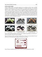
frequently used in practice. They are shown in Figure 13.14.
1. Ribbed domes (a)
2. Schwedler domes (b)
3. Three-way grid domes (c)
4. Lamella domes (d, e)
5. Geodesic domes (f)
Ribbed domes are the earliest type of braced domes that were constructed (Figure 13.14a). A
ribbed dome consists of a number of identical meridional solid girders or trusses, interconnected at
the crown by a compression ring. The ribs are also connected by concentric rings to form grids in a
trapezium shape. The ribbed dome is usually stiffened by a steel or reinforced concrete tension ring
at its base.
A Schwedler dome also consists of meridional ribs connected together to a number of horizontal
polygonal rings to stiffen the resulting structure so that it will be able to take unsymmetrical loads
(Figure 13.14b). Each trapezium formed by intersecting meridional ribs with horizontal rings is
subdivided intotwotriangles by a diagonal member. Sometimes the trapezium mayalsobesubdivided
by two cross-diagonal members. This type of dome was introduced by a German engineer, J.W.
Schwedler, in 1863. The great popular ity of Schwedler domes is due to the fact that, on the assumption
of pin-connectedjoints, the structure can be analyzed as statically determinate. In practice, in addition
c
1999 by CRC Press LLC
to axial forces, all the members are also under the action of bending and torsional moments. Many
attempts have been made in the past to simplify their analysis, but precise methods of analysis using
computers have finally been applied to find the actual stress distribution.
The construction of a three-way grid dome is self-explanatory. It may be imagined as a curved
form of three-way double layer grids (Figure 13.14c). It can also be constructed in single layer for the
dome. The Japanese “Diamond Dome” system by Tomoegumi Iron Works belongs to this category.
The theoretical analysis of three-way grid domes shows that even under unsymmetrical loading the
forces in this configuration are very evenly distributed leading to economy in material consumption.
A Lamella dome is formed by intersecting two-way ribs diagonally to form a rhombus-shaped grid
pattern. As in a lamella braced barrel vault, each lamella element has a length that is twice the length
of the side of a diamond. The lamella dome can be distinguished further from parallel and curved
domes. For a parallel lamella as shown in Figure 13.14d, the circular plan is divided into several
sectors (usually six or eight), and each sector is subdiv ided by parallel ribs into rhombus grids of
the same size. This type of lamella dome is very popular in the U.S. It is sometimes called a Kiewitt
dome, named after its developer. For a curved lamella as shown in Figure 13.14e, rhombus grids of
different size, gradually increasing from the center of the dome, are formed by diagonal ribs along
the radial lines. Sometimes, for the purpose of establishing purlins for roof decks, concentric rings
are introduced and a triangular network is generated.
FIGURE 13.14: Braced domes.
c
1999 by CRC Press LLC
The geodesic dome was developed by the American designer Buckminster Fuller, who turned
architects’ attention to the advantages of braced domes in which the elements forming the framework
of the structure are lying on the great circle of a sphere. This is where the name “geodesic” came from
(Figure 13.14f). The framework of these intersecting elements forms a three-way grid comprising
virtually equilateral spherical triangles. In Fuller’s original geodesic domes, he used an icosahedron
as the basis for the geodesic subdivision of a sphere, then the spherical surface is divided into 20
equilateral triangles as shown in Figure 13.15a. This is the maximum number of equilateral triangles
into which a sphere can be divided. For domes of larger span, each of these triangles can be subdivided
into six triangles by drawing medians and bisecting the sides of each triangle. It is therefore possible
to form 15 complete great circles regularly arranged on the surface of a sphere (see Figure 13.15b).
Practice shows that the primary type of bracing, which is truly geodesic, is not sufficient because it
would lead to an excessive length for members in a geodesic dome. Therefore, a secondary bracing
has to be introduced. To obtain a more or less regular network of the bracing bars, the edges of the
basic triangle are divided modularly. The number of modules into which each edge of the spherical
icosahedron is divided depends mainly on the size of the dome, its span, and the type of roof cladding.
This subdivision is usually referred to as “frequency” as depicted in Figure 13.15c. It must be pointed
out that during such a subdivision, the resulting triangles are no longer equilateral. The members
forming the skeleton of the dome show slight variation in their length. As the frequency of the
subdivision increases, the member length reduces, and the number of components as well as the
types of connecting joints increases. Consequently, this reflects in the increase of the final price of the
geodesic dome, and is one of the reasons why geodesic domes, in spite of their undoubted advantages
for smaller spans, do not compare equally well with other types of braced domes for larger spans.
The rise of a braced dome can be as flat as 1/6 of the diameter or as high as 3/4 of the diameter
which will constitute a greater part of a sphere. For diameter of braced domes larger than 60 m,
double layer grids are recommended. The ratio of the depth to the diameter is in the range of 1/30
to 1/50. For long spans, the depth can be taken as small as 1/100 of diameter.
The subdivision of the surface of a braced dome can also be considered by using one of the following
three methods. The first method is based on the surface of revolution. The first set of lines of division
is drawn as the meridional lines from the apex. Next, circumferential rings are added. This results in
a ribbed dome and further a Schwedler dome. Alternately, the initial set may be taken as a series of
spiral arcs, resulting in a division of the surface into triangular units as uniform as possible. This is
achieved by drawing great circles in three directions as show in the case of a grid dome. A noteworthy
type of division of a braced dome is the parallel lamella dome which is obtained by combining the
first and second methods described above. The third method of subdivision results from projecting
the edges of in-polyhedra onto the spherical surface, and then inscribing a triangular network of
random frequency into this basic grid. A geodesic dome represents an application of this method,
with the basic field derived from the isosahedron further subdivided with equilateral triangles.
13.3.4 Hyperbolic Paraboloid Shells
The hyper bolic paraboloid or hypar is a translational surface formed by sliding a concave paraboloid,
called a generatrix, parallel to itself along a convex parabola, called a directrix, which is perpendicular
to the generatrix (Figure 13.16a). By cutting the surface vertically, parabolas can be obtained and
by cutting horizontally hyperbolas can be obtained. Such surfaces can also be formed by sliding a
straig ht line along two other straight lines skewed with respect to each other (Figure 13.16b). The
hyperbolic paraboloid is a doubly ruled surface; it can be defined by two families of intersecting
straight lines that form in plan projection a rhombic grid. This is one of the main advantages of a
hyperbolic paraboloid shell. Although it has a double curvature anticlastic surface, it can be built by
using linear structural members only. Thus, single layer hypar shells can be fabricated from str aight
beams and double layer hypar shells from linear latticed trusses. The single hypar unit shown in
c
1999 by CRC Press LLC
FIGURE 13.15: Geodesic subdivision.
Figure 13.16 is suitable for use in building of square, rectangular, or elliptic plan. In practice, there
exist an infinite number of ways of combining hypar units to enclose a given building space.
FIGURE 13.16: Hyperbolic paraboloid shells.
A shallow hyperbolic paraboloid under uniform loading acts primarily as a shear system, where
the shear forces, in turn, causes diagonal tension and compression. The behavior of the surface can
c
1999 by CRC Press LLC