Basic Theory of Plates and Elastic Stability - Part 12 ppsx
Bạn đang xem bản rút gọn của tài liệu. Xem và tải ngay bản đầy đủ của tài liệu tại đây (486.49 KB, 77 trang )
Richard Liew, J.Y.; Balendra, T. and Chen, W.F. “Multistory Frame Structures”
Structural Engineering Handbook
Ed. Chen Wai-Fah
Boca Raton: CRC Press LLC, 1999
Multistory Frame Structures
J. Y. Richard Liew
and T. Balendra
Department of Civil Engineering,
National University of Singapore,
Singapore, Singapore
W. F. Chen
School of Civil Engineering,
Purdue University,
West Lafayette, IN
12.1 Classification of Building Frames
Rigid Frames
•
SimpleFrames (Pin-ConnectedFrames)
•
Brac-
ing Systems
•
Braced Frames vs. Unbraced Frames
•
Sway
Frames vs. Non-Sway Frames
•
Classification of Tall Build-
ing Frames
12.2 Composite Floor Systems
Floor Structures in Multistory Buildings
•
Composite Floor
Systems
•
Composite Beams and Girders
•
Long-Span Floor-
ing Systems
•
Comparison of Floor Spanning Systems
•
Floor
Diaphragms
12.3 Design Concepts and St ructural Schemes
Introduction
•
Gravity Frames
•
Bracing Systems
•
Moment-
Resisting Frames
•
Tall Building Framing Systems
•
Steel-
Concrete Composite Systems
12.4 Wind Effects on Buildings
Introduction
•
Characteristics of Wind
•
Wind Induced Dy-
namic Forces
•
ResponseDueto Along Wind
•
ResponseDueto
Across Wind
•
Torsional Response
•
Response by Wind Tunnel
Tests
12.5 Defining Terms
References
Further Reading
12.1 Classification of Building Frames
For building frame design, it is useful to define various frame systems in order to simplify models of
analysis. For example, in the case of a braced frame, it is not necessary to separate frame and bracing
behavior because both can be analyzed with a single model. On the other hand, for more complicated
three-dimensional structures involving the interaction of different structural systems, simple models
are useful for preliminary design and for checking computer results. These models should be able to
capture the behavior of individual subframes and their effects on the overall structures.
The remainder of this section attempts to describe what a framed system represents, define when a
framed system can be considered to be braced by another system, what is meant by a bracing system,
and the difference between sway and non-sway frames. Various structural schemes for tall building
construction are also given.
12.1.1 Rigid Frames
A rigid frame derives its lateral stiffness mainly from the bending rigidity of frame members inter-
connected by rigid joints. The joints shall be designed in such a manner that they have adequate
c
1999 by CRC Press LLC
strength and stiffness and negligible deformation. The deformation must be small enough to have
any significant influence on the distribution of internal forces and moments in the structure or on
the overall frame deformation.
A rigid unbraced frame should be capable of resisting lateral loads without relying on an additional
bracing system for stability. The frame, by itself, has to resist all the design forces, including gravity
as well as lateral forces. At the same time, it should have adequate lateral stiffness against sidesway
when it is subjected to horizontal wind or earthquake loads. Even though the detailing of the rigid
connections results in a less economic structure, rigid unbraced frame systems have the following
benefits:
1. Rigid connections are more ductile and therefore the structure performs better in load
reversal situations or in earthquakes.
2. From the architectural and functional points of view, it can be advantageous not to have
any triangulated bracing systems or solid wall systems in the building.
12.1.2 Simple Frames (Pin-Connected Frames)
A simple frame refers to a structural system in which the beams and columns are pinned connected
and the system is incapable of resisting any lateral loads. The stability of the entire structure must
be provided for by attaching the simple frame to some form of bracing system. The lateral loads are
resisted by the bracing systems while the gravity loads are resisted by both the simple frame and the
bracing system.
In most cases, the lateral load response of the bracing system is sufficiently small such that second-
order effects may be neglected for the design of the frames. Thus, the simple frames that are at-
tached to the bracing system may be classified as non-sway frames. Figure 12.1 shows the principal
components—simply frame and bracing system—of such a structure.
There are several reasons of adopting pinned connections in the design of steel multistory frames:
1. Pin-jointed frames are easier to fabricate and erect. For steel structures, it is more conve-
nient to join the webs of the members without connecting the flanges.
2. Bolted connections are preferred over welded connections, which normally require weld
inspection, weather protection, and surface preparation.
3. It is easier to design and analyze a building structure that can be separated into system
resisting vert ical loads and system resisting horizontal loads. For example, if all the girders
are simply supported between the columns, the sizing of the simply supported girders
and the columns is a straightforward task.
4. It is more cost effective to reduce the horizontal drift by means of bracing systems added
to the simple framing than to use unbraced frame systems with rigid connections.
Actual connections in structures do not always fall within the categories of pinned or rigid connec-
tions. Practical connections are semi-rigid in nature and therefore the pinned and rigid conditions
are only idealizations. Modern design codes allow the design of semi-rigid frames using the concept
of wind moment design (type 2 connections). In wind moment design, the connection is assumed
to be capable of transmitting only part of the bending moments (those due to the wind only). Recent
development in the analysis and design of semi-rigid frames can be obtained from Chen et al. [15].
Design guidance is given in Eurocode 3 [22].
c
1999 by CRC Press LLC
FIGURE 12.1: Simple br aced frame.
12.1.3 Bracing Systems
Bracing systems refer to structures that can provide lateral stability to the overall framework. It may
be in the form of triangulated frames, shear wall/cores, or rigid-jointed frames. It is common to
find bracing systems represented as shown in Figure 12.2. They are normally located in buildings to
accommodate lift shafts and staircases.
In steel structures, it is common to represent a bracing system by a triangulated truss because,
unlike concrete st ructures where all the joints are naturally continuous, the most immediate way
of making connections between steel members is to hinge one member to the other. As a result,
common steel building structures are designed to have bracing systems in order to provide sidesway
resistance. Therefore, bracing can only be obtained by use of triangulated trusses (Figure 12.2a) or,
exceptionally, by a very stiff structure such as shear wall or core wall (Figure 12.2b). The efficiency
of a building to resist lateral forces depends on the location and the types of the bracing systems
employed, and the presence or absence of shear walls and cores around lift shafts and stair wells.
12.1.4 Braced Frames vs. Unbraced Frames
The main function of a bracing system is to resist lateral forces. Building frame systems can be
separated into vertical load-resistance and horizontal load-resistance systems. In some cases, the
vertical load-resistance system also has some capability to resist horizontal forces. It is necessary,
therefore, to identify the two sources of resistance and to compare their behavior with respect to
the horizontal actions. However, this identification is not that obvious since the bracing is integral
within the structure. Some assumptions need to be made in order to define the two structures for
the purpose of comparison.
Figures 12.3 and 12.4 represent the structures that are easy to define within one system: two sub-
assemblies identifying the bracing system and the system to be braced. For the structure shown in
Figure 12.3, there is a clear separation of functions in which the gravity loads are resisted by the
hinged subassembly (Frame B) and the horizontal load loads are resisted by the braced assembly
c
1999 by CRC Press LLC
FIGURE 12.2: Common bracing systems: (a) vertical truss system and (b) shear wall.
FIGURE 12.3: Pinned connected frames split into two subassemblies.
(Frame A). In contrast, for the structure in Figure 12.4, since the second sub-assembly (Frame B) is
able to resist horizontal actions as well as vertical actions, it is necessary to assume that practically all
the horizontal actions are carried by the first sub-assembly (Frame A) in order to define this system
as braced.
Eurocode3[22] gives a clear guidance in defining braced and unbraced frames. A frame may be
classified as braced if its sway resistance is supplied by a bracing system in which its response to lateral
loads is sufficiently stiff for it to be acceptably accurate to assume all horizontal loads are resisted by
the bracing system. The frame can be classified as braced if the bracing system reduces its horizontal
displacement by at least 80%.
c
1999 by CRC Press LLC
FIGURE 12.4: Mixed frames split into two subassemblies.
For the frame shown in Figure 12.3, the hinged frame (Frame B) has no lateral stiffness, and Frame
A (truss frame) resists all lateral load. In this case, Frame B is considered to be braced by Frame A.
For the frame shown in Figure 12.4, Frame B may be considered to be a braced frame if the following
deflection criterion is satisfied:
1 −
A
B
≥ 0.8
(12.1)
where
A
= lateral deflection calculated from the truss frame (Frame A) alone
B
= lateral deflection calculated from Frame B alone
Alternatively, the lateral stiffness of Frame A under the applied lateral load should be at least five
times larger than that of Frame B:
K
A
≥ 5K
B
(12.2)
where
K
A
= lateral stiffness of Frame A
K
B
= lateral stiffness of Frame B
12.1.5 Sway Frames vs. Non-Sway Frames
The identification of sway frames and non-sway frames in a building is useful for evaluating safety of
structures against instability. In the desig n of multi-story building frame, it is convenient to isolate the
columns from the frame and treat the stability of columns and the stability of frames as independent
problems. For a column in a braced frame, it is assumed that the columns are restricted at their ends
from horizontal displacements and therefore are only subjected to end moments and axial loads as
transferred from the frame. It is then assumed that the frame, possibly by means of a bracing system,
satisfies global stability checks and that the global stability of the frame does not affect the column
behavior. This gives the commonly assumed non-sway frame. The design of columns in non-sway
frames follows the conventional beam-column capacity check approach, and the column effective
length may be evaluated based on the column end restraint conditions. Interaction equations for
various cross-section shapes have been developed through years of research spent in the field of
beam-column design [12].
Another reason for defining “sway” and “non-sway frames” is the need to adopt conventional
analysis in which all the internal forces are computed on the basis of the undeformed geometry
of the structure. This assumption is valid if second-order effects are negligible. When there is
an interaction between overall frame stability and column stability, it is not possible to isolate the
column. The column and the frame have to act interactively in a “sway” mode. The design of sway
frames has to consider the frame subassemblage or the structure as a whole. Moreover, the presence
of “inelasticity” in the columns will render some doubts on the use of the familiar concept of “elastic
effective length” [45, 46].
c
1999 by CRC Press LLC
On the basis of the above considerations, a definition can be established for sway and non-sway
frames as:
Aframe canbeclassified as non-swayifitsresponse toin-planehorizontal forcesis sufficiently
stiff for it to be acceptably accurate to neglect any additional internal forces or moments
arising from horizontal displacements of its nodes.
British Code: BS5950:Part 1 [11] provides a procedure to distinguish between sway and non-sway
frames as follows:
1. Apply a set of notional horizontal loads to the frame. These notional forces are to be taken
as 0.5% of the factored dead plus vertical imposed loads and are applied in isolation, i.e.,
without the simultaneous application of actual vertical or horizontal loading.
2. Carry out a first-order linear elastic analysis and evaluate the individual relative sway
deflection δ for each story.
3. If the actual frame is uncladed, the frame may be considered to be non-sway if the inter-
story deflection of every story satisfies the following limit:
δ<
h
4000
where h = story height.
4. If the actual frame is claded but the analysis is carried out on the bare frame, then in
recognition of the fact that the cladding will substantially reduce deflections, thecondition
is reflected and the frame may be considered to be non-sway if
δ<
h
2000
where h = story height.
5. All frames not complying with the criteria in (3) or (4) are considered to be sway frames.
Eurocode3[22] also provides some guidelines to distinguish between sway and non-sway frames.
It states that a frame may be classified as non-sway for a given load case if the elastic buckling load
ratio P
cr
/P for that load case satisfies the criterion:
P
cr
/P ≥ 10
where P
cr
is the elastic critical buckling value for sway buckling and P is the design value of the
total vertical load. When the system buckling load is 10 times the design load, the frame is said to
be stiff enough to resist lateral load, and it is unlikely to be sensitive to sidesway deflections. AISC
LRFD [3] does not give specific guidance on frame classification. However, for frames to be classified
as non-sway in AISC LRFD for mat, the moment amplification factor, B
2
, has to be small (a possible
range is B
2
< 1.10) so that sway deflection would have neg ligible influence on the final value obtained
from the beam-column capacity check.
12.1.6 Classification of Tall Building Frames
A tall building is defined uniquely as a building whose structure creates different conditions in its
design, construction, and use than those for common buildings. From the structural engineer’s view
point, the selection of appropriate structural systems for tall buildings must satisfy two important
criteria: strength and stiffness. The structural system must be adequate to resist lateral and gravity
c
1999 by CRC Press LLC
loads that cause horizontal shear deformation and overturning deformation. Other important issues
that must be considered in planning the structural schemes and layout are the requirements for
architectural details, building services, vertical transportation, and fire safety, among others. The
efficiency of a structural system is measured in terms of its ability to resist hig her lateral loads which
increase with the height of the frame [30]. A building can be considered as tall when the effect of
lateral loads is reflected in the design. Lateral deflections of tall buildings should be limited to prevent
damage to both structural and non-structural elements. The accelerations at the top of the building
during frequent windstorms should be kept within acceptable limits to minimize discomfort to the
occupants (see Section 12.4).
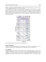
Figure 12.5 shows a chart that defines, in general, the limits to which a particular system can be
used efficiently for multi-story building projects. The various structural systems in Figure 12.5 can
be broadly classified into two main types: (1) medium-height buildings with shear-type deformation
predominant and (2) high-rise cantilever structures, such as fr amed tubes, diagonal tubes, and br aced
trusses. This classification of system forms is based primarily on their relative effectiveness in resisting
lateral loads. At one end of the spectrum in Figure 12.5 is the moment resisting frames, which are
efficient for buildings of 20 to 30 stories, and at the other end is the tubular systems with high
cantilever efficiency. Other systems were placed with the idea that the application of any particular
form is economical only over a limited range of building heights.
An attempt has been made to develop a r igorous methodology for the cataloging of tall buildings
with respect to their structural systems [16]. The classification scheme involves four levels of framing
division: (1)primary framing system, (2) bracing subsystem, (3) floor framing, and (4) configuration
and load transfer. While any catalog ing scheme must address the pre-eminent focus on lateral load
resistance, the load-carrying function of the tall building subsystems is rarely independent. An
efficient high-rise system must engage vertical gravity load resisting elements in the lateral load
subsystem in order to reduce the overall structural premium for resisting lateral loads. Further
readings on design concepts and structural schemes for steel multi-story buildings can be found in
Liew [41], and the design calculations and procedures for building frame structures using the AISC
LRFD procedure are given in Liew and Chen [44].
Some degree of independence can be distinguished between the floor framing systems and the
lateral load resisting systems, but the integration of these subassemblies into the overall structur al
scheme is crucial. Section 12.2 provides some advice for selecting composite floor systems to achieve
the required stiffness and strength, and also hig hlights the ways where building services can be
accommodated within normal floor zones. Several practical options for long-span construction are
discussed, and their advantages and limitations are compared and contrasted. Design considerations
for floor diaphragms are discussed. Section 12.3 provides some advice on the general principles to be
applied when preparing a structural scheme for multistory steel and composite frames. The design
procedure and construction considerations that are specific to steel gravity frames, braced frames,
moment resisting frames, and the design approaches to be adopted for sizing multistory building
frames are given. The potential use of steel-concrete composite material for high-rise construction
is presented. Section 12.4 deals with the issues related to wind-induced effects on multistory frames.
Dynamic effects due to along wind, across wind, and torsional response are considered with examples.
12.2 Composite Floor Systems
12.2.1 Floor Structures in Multistory Buildings
Tall building floor structures generally do not differ substantially from those in low-rise buildings;
however, there are certain aspects and properties that need to be considered in design:
1. Floor weight to be minimized.
c
1999 by CRC Press LLC
FIGURE 12.5: Various structural schemes.
2. Floor should be able to resist construction loads during the erection process.
3. Integration of mechanical services (such as ducts and pipes) in the floor zone.
4. Fire resistance of the floor system.
5. Buildability of structures.
6. Long spanning capability.
Modern office buildings require large floor spans in order to create greater space flexibility for the
accommodation of a greater variety of tenant floor plans. For tall building design, it is necessary to
reduce the weight of the floors so as to reduce the size of columns and foundations and thus permit
the use of larger space. Floors are required to resist vertical loads and they are usually supported by
secondary beams. The spacing of the supporting beams must be compatible with the resistance of
the floor slabs.
The floor systems can be made buildable by using prefabricated or precasted elements of steel
and reinforced concrete in various combinations. Floor slabs can be precasted concrete slab, in situ
concrete slab, or composite slabs with metal decking. Typical precast slabs are 4 to 7 m, thus avoiding
c
1999 by CRC Press LLC
the need of secondary beams. For composite slabs, metal deck spans ranging from 2 to7mmaybe
used depending on the depth and shape of the deck profile. However, the permissible spans for steel
decking are influenced by the method of construction; in particular, it depends on whether shoring
is provided. Shoring is best avoided as the speed of construction is otherwise diminished for the
construction of tall buildings.
Sometimes openings in the webs of beams are required to permit passage of horizontal serv ices,
such as pipes (for water and gas), cables (for electricity and tele and electronic communication),
ducts (air-conditioning), etc.
In addition to strength, floor spanning systems must provide adequate stiffness to avoid large
deflections due to live load which could lead to damage of plaster and slab finishers. Where the
deflection limit is too severe, pre-cambering with an appropriate initial deformation equal and
opposite to that due to the permanent loads can be employed to offset part of the deflection. In
steel construction, steel members can be partially or fully encased in concrete for fire protection. For
longer periods of fire resistance, additional reinforcement bars may be required.
12.2.2 Composite Floor Systems
Composite floor systems typically involve structural steel beams, joists, girders, or trusses linked via
shear connectors with a concrete floor slab to for m an effective T-beam flexural member resisting
primarily gravity loads. The versatility of the system results from the inherent strength of the concrete
floor component in compression and the tensile strength of the steel member. The main advantages
of combining the use of steel and concrete materials for building construction are:
1. Steel and concrete may be arranged to produce ideal combinations of strength, with
concrete efficient in compression and steel in tension.
2. Composite system is lighter in weight (about 20 to 40% lighter than concrete construc-
tion). This leads to savings in the foundation cost. Because of its light weight, site erection
and installation are easier and thus labor cost can be minimized. Foundation cost can
also be reduced.
3. The construction time is reduced because casting of additional floors may proceed without
having to wait for the previously casted floors to gain strength. The steel decking system
provides positive-moment reinforcement for the composite floor and requires only small
amounts of reinforcement to control cracking and for fire resistance.
4. The construction of composite floors does not require highly skilled labor. The steel
decking acts as a permanent formwork. Composite beams and slabs can accommodate
raceways for electrification, communication, and an air distribution system. The slab
serves as a ceiling surface to provide easy attachment of a suspended ceiling.
5. The composite slabs, when they are fixed in place, can act as an effective in-plane di-
aphragm that may provide effective lateral bracing to beams.
6. Concrete provides corrosion and thermal protection to steel at elevated temperatures.
Composite slabs of 2-h fire r ating can be achieved easily for most building requirements.
Composite floor systems are advantageous because of the formation of the floor slab. The
floor slab can be formed by the following methods:
(a) a flat-soffit reinforced concrete slab (Figure 12.6a)
(b) precast concrete planks with cast in situ concrete topping (Figure 12.6b)
(c) precast concrete slab with in situ grouting at the joints (Figure 12.6c)
(d) a metal steel deck, either composite or non-composite (Figure 12.6d)
c
1999 by CRC Press LLC
FIGURE 12.6: Composite beams with (a) flat-soffit reinforced concrete slab, (b) precast concrete
planks and cast in situ concrete topping, (c) precast concrete slab and in situ concrete at the joints,
and (d) metal steel deck supporting concrete slab.
The composite action of the beam or truss is due to shear studs welded directly through the metal
deck, whereasthe composite action of the metal deck results from side embossments incorporated into
the steel sheet profile. The slab and beam arrangement typical in composite floor systems produces
a rigid horizontal diaphragm, providing stability to the overall building system while distributing
wind and seismic shears to the lateral load resisting systems.
12.2.3 Composite Beams and Girders
Steel and concrete composite beams may be formed by completely encasing a steel member in
concrete with the composite action depending on the shear connectors connecting the concrete floor
to the top flange of the steel member. Concrete encasement will provide fire resistance to the steel
member. Alternatively, instead of using concrete encasement, direct sprayed-on cementitious and
board-type fireproofing materials may be used economically to replace the concrete insulation on
the steel members. The most common arrangement found in composite floor systems is a rolled or
built-up steel beam connected to a formed steel deck and concrete slab (Figure 12.6d). The metal
c
1999 by CRC Press LLC
deck typically spans unsupported between steel members while also providing a working platform
for concreting work. The metal decks may be oriented parallel or perpendicular to the composite
beam span.
Figure12.7a shows a typical building floor plan using compositesteelbeams. Thestress distribution
at working loads in a composite section is shown schematically in Figure 12.7b. The neutral axis is
normally located very near to the top flange of the steel section. Therefore, the top flange is lightly
stressed. Built-up beams or hybrid composite beams can be good choices in an attempt to use the
structural steel material more efficiently (see Section 12.2.4). Also, composite beams of tapered
FIGURE 12.7: (a) Composite floor plan and (b) stress distribution in a composite cross-section.
flanges are possible. For a construction point of view, a relatively wide and thick top flange must be
provided for proper installation of shear stud and metal decking. However, in all of these cases, the
increased fabrication costs must be evaluated, which tend to offset the saving from material efficiency.
A prismatic compositesteel beam has two fundamental disadvantagesover other types of composite
floor framing t ypes.
c
1999 by CRC Press LLC
1. The member must be designed for the maximum bending moment near midspan and
thus is often under stressed near the supports.
2. Building-serv ices ductwork and piping must pass beneath the beam, or the beam must be
provided with web openings (normally reinforced with plates or angles leading to higher
fabrication costs) to allow access for this equipment as shown in Figure 12.8.
FIGURE 12.8: We b opening with horizontal reinforcements.
For this reason, a number of composite girder forms allowing the free passage of mechanical ducts
and related services through the depth of the girder have been developed. Successful composite beam
design requires the consideration of various serviceability issues such as long-term (creep) deflections
and floor vibrations. Of particular concern is the occupant-induced floor vibrations. The relatively
high flexural stiffness of most composite floor framing systems results in relatively low vibration
amplitudes and therefore is effective in reducing perceptibility. Studies have shown that short to
medium span (6 to 12 m) composite floor beams perform quite well and are rarely found to transmit
annoying vibrations to the occupants. Particular care is required for long span beams more than 12 m
in range. Issues related to serviceabilit y problems at various deflection or drift indices are discussed
in Section 12.4.
12.2.4 Long-Span Flooring Systems
Long spans impose a burden on the beam design in terms of larger required flexural stiffness for limit-
state designs. Besides satisfying both serviceabilit y and ultimate strength limit states, the proposed
system must also accommodate the incorporation of mechanical services within normal floor zones.
Several practical options for long-span construction are available and the y are discussed in the
following subsections.
Beams With Web Openings
Standard castellated beams can be fabricated from hot-rolled beams by cutting along a zigzag
line through the web. The top and bottom half-beams are then displaced to form castellations
(Figure 12.9). Castellated composite beams can be used effectively for lightly serviced buildings.
Although composite action does not increase the strength significantly, it increases the stiffness,
and hence reduces deflection and the problem associated with vibration. Castellated beams have
limited shear capacity and are best used as long span secondary beams where loads are low or where
concentrated loads can be avoided. Their use may be limited due to the increased fabrication cost
and the fact that the standard castellated openings are not large enough to accommodate the large
mechanical ductwork common in modern high-rise buildings.
c
1999 by CRC Press LLC
FIGURE 12.9: Composite castellated beams.
Horizontal stiffeners may be required to strengthen the web opening , and they are welded above
and below the opening. The height of the opening should not be more than 70% of the beam depth,
and the length should not be more than twice the beam depth. The best location of the openings is
in the low shear zone of the beams, i.e., where the bending moment is high. This is because the webs
do not contribute much to the moment resistance of the beam.
Fabricated Tapered Beams
The economic advantage of fabricated beams is that they can be designed to provide the required
moment and shear resistance along the beam span in accordance with the loading pattern along the
beam. Several forms of tapered beams arepossible. Asimplysupported beam design with a maximum
bending moment at the mid-span would require that they all effectively taper to a minimum at both
ends (Figure 12.10), whereas a rigidly connected beam would have a minimum depth towards the
mid-span. To make best use of this system, services should be placed towards the smaller depth of
the beam cross-sections. The spaces created by the tapered web can be used for running services of
modest size (Figure 12.10).
FIGURE 12.10: Tapered composite beams.
A hybrid girder can be formed w ith the top flange made of lower-strength steel in comparison
with the steel grade for the bottom flange. The web plate can be welded to the flanges by double-
sided fillet welds. Web stiffeners may be required at the change of section when taper slope exceeds
c
1999 by CRC Press LLC
approximately 6
◦
. Stiffeners are also required to enhance the shear resistance of the web especially
when the web slenderness ratio is too high. Tapered beam is found to be economical for spans of 13
to 20 m. Further information on the design of fabricated beams with tapered webs can be found in
Owens [51].
Haunched Beams
The span length of a composite beam can be increased by providing haunches or local stiffening
of the beam-to-column connections as shown in Figure 12.11. Haunched beams are designed by
FIGURE 12.11: Haunched composite beam.
forming a rigid moment connection between the beams and columns. The haunch connections
offer restraints to the beam and it helps to reduce mid-span moment and deflection. The beams are
designed in a manner similar to continuous beams. Considerable economy can be gained in sizing
the beams using continuous design which may lead to a reduction in beam depth up to 30% and
deflection up to 50%.
The haunch may be designed to develop the required moment which is larger than the plastic
moment resistance of the beam. In this case, the cr itical section is shifted to the tip of the haunch. The
depth of the haunch is selected based on the required moment at the beam-to-column connections.
The length of haunch is typically 5 to 7% the span length for non-sway frames or 7 to 15% for sway
frames. Service ducts can pass below the beams as in conventional construction (Figure 12.11).
Haunched composite beams are usually used in the case where the beams frame directly into the
major axis of the columns. This means that the columns must be designed to resist the moment
transferred from the beam to the column. Thus, a heavier column and a more complex connection
would be required in comparison with a structure design based on the assumption that the connec-
tions are pinned. The rigid frame action derived from the haunched connections can resist lateral
loads due to wind without the need of vertical bracing. Haunched beams do offer higher strength
and stiffness during the steel erection stage thus making this type of system particularly attractive
for long span construction. However, haunched connections behave differently under positive and
negative moments, as the connection configuration is not symmetrical about the bending axis.
The rationale of using the haunched beam approach is explained as follows. In continuous beam
design, the moment distribution of a continuous beam would show that the support moment is
generally larger than the mid-span moment up to the ratio of 1.8 times. The effective cross-sections
of typical steel-concrete composite beam under hogging and sagging moment can be determined
according to the usual stress block method of desig n. It can be observed that the hogging moment
capacity of the composite section at the support is smaller than the sagging moment capacity near
the mid-span. Therefore, there is a mismatch between the required greater support resistance and
the much larger available sagging moment capacity.
c
1999 by CRC Press LLC
When elastic analysis is used in the design of continuous composite beams, the potential large
sagging moment capacities available from composite action can never be realized. One way to
overcome this problem is to increase the moment resistance at the support (and hence utilize the full
potential of larger sagging moment) by providing haunches at the supports. An optimum design can
be achieved by designing the haunched section to develop the required moment at the support and
the composite section to develop the required sagging moment. If this can be achieved in practice, the
design does not require inelastic force redistribution and hence elastic analysis is adequate. However,
analysis of haunched compositebeamsismorecomplicatedbecause the member is non-prismatic (i.e.,
cross-section property varies along the length). The analysis of such beams requires the evaluation
of section properties such as the beam’s stiffness (EI ) at different cross-sections. The analysis/design
process is more involved because it requires the evaluation of serviceability deflection and ultimate
strength limit state of non-prismatic members. Some guides on haunched beam design can be found
in Lawson and Rackham [36].
Parallel Beam System
The system consists of two main beams with secondary beams run over the top of the main
beams (see Figure 12.12). The main beams are connected to either side of the column. They can
FIGURE 12.12: Parallel composite beam system.
be made continuous over two or more spans supported on stubs attached to the columns. This will
help in reducing the construction depth, and thus avoiding the usual beam-to-column connections.
The secondary beams are designed to act compositely with the slab and may also be made to span
continuously over the main beams. The need to cut the secondary beams at every junction is
thus avoided. The parallel beam system is ideally suited for accommodating large service ducts in
orthogonal directions (Figure 12.12). Small savings in steel weight are expected from the continuous
construction because the pr imary beams are non-composite. However, the main beam can be made
composite with the slab by welding beam stubs to the top flange of the main beam and connecting
to the concrete slab through the use of shear studs (see the stud-girder system in Section 12.2.4).
c
1999 by CRC Press LLC
The simplicity of connections and ease of fabrication make this long-span beam option particularly
attractive. Competitive pricing can be obtained from the fabricator. Further details on the parallel
beam approach can be found in Brett and Rushton [10].
Composite Trusses
Trusses are frequently used in multistory buildings for very long span supports. The openings
created in the truss braces can be used to accommodate large services. Although the cost of fabrication
is higher in relation to the mater ial cost, truss const ruction can be cost-effective for very long spans
when compared to other structural schemes. An additional disadvantage other than fabrication cost
is that t russ configuration creates difficulty for fire protection. Fire protection wrapping is labor
intensive and sprayed-protection systems cause a substantial mess to the services that pass through
the web opening (see Figure 12.13). From a structural point of view, the benefit of using a composite
truss is due to the increase in stiffness rather than strength.
FIGURE 12.13: Composite truss.
Several forms of truss arrangement are possible. The three most common web framing configura-
tions in floor truss and joist designs are: (1) Warren Truss, (2) Modified Warren Truss, and (3) Pratt
Truss as shown in Figure 12.14. The efficiency of various web members in resisting vertical shear
forces may be affected by the choice of a web-framing configuration. For example, the selection
of Pratt web over Warren web may effectively shorten compression diagonals resulting in a more
efficient use of these members.
Experience has shown that both Pratt and Warren configurations of web framing are suitable
for short span tr usses with shallow depths. For truss with spans g reater than 10 m, or effective
depths larger than 700 mm, a modified Warren configuration is generally preferred. The Warren
and modified Warren trusses are more popular for building construction since they offer larger web
openings for services between bracing members.
The resistance of a composite truss is governed by (1) yielding of the bottom chord, (2) crushing of
the concrete slab, (3) failure of the shear connectors, (4) buckling of top chord during construction,
(5) buckling of web members, and (6) instability occurring during and after construction. To avoid
brittle failures, ductile yielding of the bottom chord is the preferred failure mechanism. Thus,
the bottom chord should be designed to yield prior to crushing of the concrete slab. The shear
connectors should have sufficient capacity to transfer the horizontal shear between the top chord
and the slab. During construction, adequate plan bracing should be provided to prevent top chord
buckling. When composite action is considered, the top steel chord is assumed not to participate in
the moment resistance of the truss because it is located very near to the neutral axis of the composite
truss and, thus, contributes very little to the flexural capacity. However, the top chord has two
functions: (1) it provides an attachment surface for the shear connectors, and (2) it resists the forces
in the end panel without reliance on composite action unless shear connectors are placed over the
c
1999 by CRC Press LLC
FIGURE 12.14: Truss configuration: (a) Warren truss, (b) Modified Warren truss, and (c) Pratt truss.
seat or along a top chord extension. Thus, the top chord must be designed to resist the compressive
force equilibrating the horizontal force component of the first web member. In addition, the top
chord also transfers the factored shear force to the support, and must be designed accordingly.
The bottom chord shall be continuous and may be designed as an axially loaded tension member.
The bottom chord shall be proportioned to yield before the concrete slab, web members, or the shear
connectors fail.
The shear capacity of the steel top and bottom chords and concrete slab can be ignored in the
evaluation of the shear resistance of a composite truss. The web members should be designed to resist
vertical shear. Further references on composite trusses can be found in ASCE Task Committee [7]
and Neals and Johnson [50].
Stub Girder System
The stub girder system involves the use of short beam stubs that are welded to the top flange
of a continuous, heavier bottom g irder member, and connected to the concrete slab through the use
of shear studs. Continuous transverse secondary beams and ducts can pass through the openings
formed by the beam stub. The natur al openings in the stub girder system allow the integration of
structural and service zones in two directions (Figure 12.15), permitting story-height reduction when
compared with some other structural framing systems.
Ideally, stub-girders span about 12 to 15 m (usually from the center core wall to the exterior columns
in a conventional office building) with the secondar y fr aming or floor beams spanning about 6 to
9 m. The system is very versatile, particularly with respect to secondary framing spans with beam
depths being adjusted to the required str uctural configuration and mechanical requirements. Overall
girder depths vary only slightly, by vary ing the beam and stub depths. The major disadvantage of
the stub girder system is that it requires temporary props at the construction stage, and these props
have to remain until the concrete has gained adequate strength for composite action. However, it is
possible to introduce an additional steel top chord, such as a T-section, which acts in compression
c
1999 by CRC Press LLC
FIGURE 12.15: Stub girder system.
to develop the required bending strength during construction. For span length greater than 15 m,
stub-girders become impr actical because the slab design becomes critical.
In the stub girder system, the floor beams are continuous over the main girders and splice at the
locations near the points of inflection. The sagging moment regions of the floor beams are usually
designed compositely with the deck-slab system, to produce savings in structural steel as well as to
provide stiffness. The floor beams are bolted to the top flange of the steel bottom chord of the stub-
girder, and two shear studs are usually specified on each floor beam, over the beam-girder connection,
for anchorage to the deck-slab system. The stub-girder may be analyzed as a vierendeel girder, with
the deck-slab acting as a compression top-chord, the full length steel girder as a tensile bottom-chord,
and the steel stubs as vertical web members or shear panels.
Prestressed Composite Beams
Prestressing of the steel girders is carried out such that the concrete slab remains uncracked
under the working loads and the steel is utilized fully in terms of st ress in the tension zone of the
girder.
Prestressing of a steel beam can be carried out using a precambering technique as depicted in Fig-
ure 12.16. First a steel girder member is prebent (Figure 12.16a), and is then subjected to preloading in
the direction against the bending curvature until the required steel strength is reached (Figure 12.16b).
Second, the lower flange of the steel member, which is under tension, is encased in a reinforced con-
crete chord (Figure 12.16c). The composite action between the steel beam and the concrete slab is
developed by providing adequate shear connectors at the interface. When the concrete gains ad-
equate strength, the steel girder is prestressed by stress-relieving the precompressed tension chord
(Figure 12.16d). Further composite action can be achieved by supplementing the girder with in
situ or prefabricated reinforcement concrete slabs, and this will produce a double composite girder
(Figure 12.16e).
The major advantages of this system is that the steel girders are encased in concrete on all sides and
no corrosion and fire protection are required on the sections. The entire process of precambering and
prestressing can be performed and automated in a factory. During construction, the lower concrete
chord cast in the works can act as a formwork. If the distance between two girders is large, precast
planks can be supported by the lower concrete chord as permanent formwork.
Prestressing can also be achieved by using tendons that can be attached to the bottom chord of a
steel composite truss or the lower flange of a composite girder to enhance the load-carrying capacity
and stiffness of long-span structures (Figure 12.17). This technique has been found to be popular for
bridge construction in Europe and the U.S., although it is less common for building construction.
c
1999 by CRC Press LLC
FIGURE 12.16: Process of prestressing using precambering technique.
FIGURE 12.17: Prestressing of composite steel girders with tendons.
12.2.5 Comparison of Floor Spanning Systems
The conventional composite beams are the most common forms of floor construction for a large
number of building projects. Typically they are highly efficient and economic with bay sizes in the
range of 6 to 12 m. There is, however, much demand for larger column free areas where, with
a traditional composite approach, the beams tend to become excessively deep, thus unnecessarily
increasing the overall building height, with the consequent increases in cladding costs, etc. Spans
exceeding 12 m are generally achieved by choosing an appropriate structural form that integrates
the services within the floor structure, thereby reducing the overall floor zone depths. Although a
long span solution may entail a small increase in structural costs, the advantages of greater flexibility
and adaptability in service and the creation of column-free space often represent the most economic
option over the design life of the building. Figure 12.18 compares the various structural options of
a typical range of span lengths used in practice.
12.2.6 Floor Diaphragms
Typically, beams and columns rigidly connected for moment resistance are placed in orthogonal
directions to resist lateral loads. Each plane frame would assume to resist a portion of the overall
c
1999 by CRC Press LLC
FIGURE 12.18: Comparison of composite floor systems.
wind shear which is determined from the individual frame stiffness in proportion to the overall
stiffness of all frames in that direction. This is based on the assumption that the lateral loads are
distributed to the various frames by the floor diaphragm which, for building structures, are normally
assumed to have adequate in-plane stiffness. In order to develop proper diaphragm action, the floor
slab must be attached to all columns and beams that participate in lateral-force resistance. For a
building relying on bracing systems to resist all lateral load, the stability of the building depends on a
rigid floor diaphragm to transfer wind shears from their point of application to the bracing systems
such as lattice frames, shear walls, or core walls.
The use of composite floor diaphragms in place of in-plane steel bracing has become an accepted
practice. The connection between slab and beams is often through shear studs that are welded
directly through the metal deck to the beam flange. The connection between seams of adjacent deck
panels is crucial and often through interlocking of panels overlapping each other. The diaphragm
stresses are generally low and can be resisted by floor slabs that have adequate thickness for most
buildings. Plan bracing is necessary when diaphragm action is not adequate. Figure 12.19a shows a
triangulated plan bracing system that resists lateral load on one side and spans between the vertical
walls. Figure 12.19b illustrates the case where the floor slab has adequate thickness and it can act as
diaphragm resisting lateral loads and transmitting the forces to the vertical walls. However, if there
is an abrupt change in lateral stiffness or where the shear must be transferred from one frame to the
other due to the termination of a lateral bracing system at a certain height, large diaphragm stresses
may be encountered and they must be accounted for through proper detailing of slab reinforcement.
Also, diaphragm stresses may be high where there are large openings in the floor, in particular at the
corners of the openings.
Diaphragms may be classified into three types, namely (1) flexible diaphragm, (2) semi-rigid
diaphragm, and (3) rigid diaphragm. Common types of floor diaphragms that can be classified as
rigid are (1) reinforced concrete slab, (2) composite slab with reinforce d concrete slab supported by
metal decking, and (3) precasted concrete slabs that are properly attached to one another. Floors
c
1999 by CRC Press LLC
FIGURE 12.19: (a) Triangulated plan bracing system and (b) concrete floor diaphragm.
that are classified as semi-rigid or flexible are steel deck without concrete fill or deck that is partially
filled with concrete. However, the rigidity of a floor system must be comparable to the stiffness of
the lateral-load resistance system. A rigid diaphragm will distribute lateral forces to the lateral-load
resisting elements in proportion to their relative rigidities. Therefore, a vertical bracing system with
high lateral stiffness will resist a greater proportion of the lateral force than a system with lower lateral
stiffness. A flexible diaphragm behaves more like a beam spanning between the lateral-load resistance
elements. It distributes lateral forces to the lateral systems on a tributary load basis, and it cannot
resist any torsional forces. Semi-rigid diaphragms deflect like a beam under load, but possess some
stiffness to distribute the loads to the lateral-load resistance systems in proportion to their rigidities.
The load distribution process is a function of the floor stiffness and the vert ical bracing stiffness.
The rigid diaphragm assumption is generally valid for most high-rise buildings (Figure 12.20a);
however, as the plan aspect ratio (b/a) of the diaphragm linking two lateral systems exceeds 3 in 1
(see the illustration in Figure 12.20b), the diaphragm may become semi-rigid or flexible. For such
cases, the wind shears must be allocated to the parallel shear frames according to the attributed area
rather than relative stiffness of the frames.
From the analysis point of view, a diaphragm is analogous to a deep beam with the slab forming
the web and the peripheral members serving as the flanges as shown in Figure 12.19b. It is stressed
principally in shear, but tension and compression forces must be accounted for in design.
A rigid diaphragm is useful to transmit torsional forces to the lateral-load resistance systems to
maintain lateral stability. Figure 12.21a shows a building frame consisting of three shear walls resisting
lateral forces acting in the direction of Wall A. The lateral load is assumed to act as a concentrated
load with a magnitude F on each story. Figure 12.21b and 12.21c show the building plan having
dimensions of L
1
and L
2
. The lateral load resisting systems are represented in the plan by the solid
lines which represent Wall A, Wall B, and Wall C. Since there is only one lateral resistance system
(Wall A) in the direction of the applied load, the loading condition creates a torsion (F
e
), and the
diaphragm tends to rotate as shown by the dashed lines in Figure 12.21a. The lateral load resistance
systems in Wall B and Wall C will provide the resistance forces to stabilize the torsional force by
c
1999 by CRC Press LLC
FIGURE 12.20: Diaphragm rigidity: (a) plan aspect ratio ≤ 3 and (b) plan aspect ratio > 3.
generating a couple of shear resistances as:
V
B
= V
C
=
Fe
L
2
Figure 12.21c illustrates the same condition except that a flexible diaphragm is used. The same
torsional tendency exists, but the flexible diaphragm is unable to generate a resisting couple in Wall
B and Wall C, and the structure will collapse as shown by the dashed lines. To maintain stability, a
minimum of two vertical bracings in the direction of the applied force is required to eliminate the
possibility of any torional effects.
The adequacy of the floor to act as a diaphrag m depends very much on its type. Pre-cast concrete
floor planks without any prestressing offer limited resistance to the racking effects of diaphragm ac-
tion. In such cases, supplementary bracing systems in the plan, such as those shown in Figure 12.19a,
are required for resistance of lateral forces. Where precast concrete floor units are employed, suffi-
cient diaphragm action can be achieved by using a reinforced structural concrete topping, so that all
individual floor planks are combined to form a single floor diaphragm. Composite concrete floors,
incorporating permanent metal decking, provide excellent diaphragm action provided that the con-
nections between the diaphragm and the peripheral members are adequate. When composite beams
c
1999 by CRC Press LLC
FIGURE 12.21: (a) Lateral force resisting systems in a building, (b) rigid diaphragm, and (c) flexible
diaphragm.
or girders are used, shear connectors will usually serve as boundary connectors and intermediate
diaphragm-to-beam connectors. By fixing the metal decking to the floor beams, an adequate floor
diaphragm can be achieved during the construction stage. It is essential at the start of the design
of structural steelworks to consider the details of the flooring system to be used because these have
a significant effect on the design of the structure. Table 12.1 summarizes the salient features of the
various types of flooring systems in terms of their diaphragm actions.
Floor diaphragms may also be designed to provide lateral restraint to columns of multi-story
buildings. In such cases, the shear required to be resisted by the floor diaphragm can be computed
from the second-order forces caused by the vertical load acting on the story deflection of the column at
the floor level under consideration. The stability force for the column may be transmitted directly to
the deck-slab through bearing and gradually transferred into the floor framing connections through
shear studs.
c
1999 by CRC Press LLC
If metal decking is used, the metal deck provides column stability dur ing erection, prior to concrete
slab placement. Column loads are much lower during construction; hence, this condition may not
be too critical. Special precaution must be given to limit the number of stories of steel erected ahead
of the concrete floor construction. Overall building stability becomes important, possibly requiring
the steel deck diaphragm to be supplemented with a concrete cover slab at various height levels in
the structure.
TABLE 12.1 Details of Typical Flooring Systems and Their Relative Merits
Degree of
Typical lateral Degree of
Floor span Typical Construction restraint diaphragm
system length (m) depth (mm) time to beams action Usage
In situ 3–6 150–250 Medium Very good Very good All categories
concrete but not often
used in
multistory
buildings
Steel 2.5–3.6 110–150 Fast Very good Very good All categories
deck unshore especially in
with in
> 3.6 multistory office
situ shore buildings
concrete
Pre-cast 3–6 110–200 Fast Fair-good Fair-good All categories
concrete with cranage
requirements
Pre- 6–9 110–200 Medium Fair-good Fair-good Multistory
stressed buildings and
concrete bridges
12.3 Design Concepts and Structural Schemes
12.3.1 Introduction
Multistory steel frames consist of a column and a beam interconnected to form a three-dimensional
structure. A building frame can be stabilized either by some form of bracing system (braced frames)
or can be stabilized by itself (unbraced frames). All building frames must be designed to resist lateral
load to ensure overall stability. A common approach is to provide a gravity framing system with one
or more lateral bracing system attached to it. This type of framing system, which is generally referred
to as simple braced frames, is found to be cost-effective for multistory buildings of moderate height
(up to 20 stor ies).
For g ravity frames, the beams and columns are pinned connected and the frames are not capable
of resisting any lateral loads. The stability of the entire structure is provided by attaching the gravity
frames to some form of bracing system. The lateral loads are resisted mainly by the bracing systems,
while the gravity loads are resisted by both the g ravity frame and the bracing system. For buildings of
moderate height, the bracing system’s response to lateral forces is sufficiently stiff such that second-
order effects may be neglected for the design of such frames.
In moment resisting frames, the beams and columns are rigidly connected to provide moment
resistance at joints, which may be used to resist lateral forces in the absence of any bracing system.
However, moment joints are rather costly to fabricate. In addition, it takes a longer time to erect a
moment frame than a gravity frame.
A cost-effective framing system for multistory buildings can be achieved by minimizing the number
of moment joints, replacing field welding by field bolting, and combining various framing schemes
with appropriate bracing systems to minimize frame dr ift. A multistory structure is most economical
and efficient when it can transmit the applied loads to the foundation by the shortest and most
c
1999 by CRC Press LLC